How to increase on-board voltage
Where and how is a diode placed in the LV circuit on the generator in order to increase the voltage in the car network and better charge the battery?
Here I propose a simple solution, raising the on-board voltage, without going anywhere in the car and its circuits. I searched in my archives and did not find the material from which I read this decision. “Structurally, voltage regulators have an upper limit of 13.6V. This is due to the “old” connection diagram, from which the new one was copied and “successfully improved”. In it, the necessary voltage from the on-board network, supplied to the regulator for comparison, passed through a chain of wires. On them it dropped to normal. According to the new scheme, we have a chronic undercharge of the battery. Which, with the arrival of winter, makes starting the engine in the cold quite problematic. But if you install a pre-heater, starting the engine will be much easier.
It should also be noted that the battery begins to absorb energy (charge) only when its temperature is above zero. Therefore, in winter, if you make short runs and the battery does not have time to warm up under the hood to at least zero (plus charging time), it will be constantly discharged. And soon it will die... It is believed that after starting the engine, in order for the battery to recover, you need to drive for at least 20 minutes. Just go, and not stand in traffic jams! How to increase the voltage in the network?
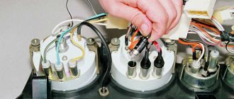
Very simple! It is necessary to make the regulator “think” that we have low voltage in the network. Thus, the generator will give us the missing volts. A diode will help us do this. In a generator with a built-in voltage regulator, you need to place a diode in the circuit, as shown in the figure.
How to increase the charge of the generator using an additional diode
How to increase generator voltage
Many motorists have encountered the concept of low voltage in the network. The culprit of the situation was the generator, which produced an insufficient amount of current. Is there any way to increase the voltage produced by the unit? How to increase the power of the generator without damaging the circuit and the overall system.
Diode introduction
Observe polarity. There is no crime here, it’s just that if the polarity is not observed, charging will not happen. The diode must be designed for a current of at least 5 A. By the way, it will get very hot, so it is better to install it on a radiator. What should you consider when selecting the type of diode? Voltage drop on diodes: germanium - 0.3...0.7 V, silicon - 0.8...1.2 V. I.e. This is the voltage by which your on-board network will increase. Therefore, by selection we can achieve the “right” voltage in our network.”
Alternator belt VAZ 2107
The generator belt has article number 21070-1308020-00 or 21010-1308020-00. The brand 21070-1308020-00 belt has a toothed shape, and the brand 21010-1308020-00 belt has a wedge shape.
Alternator belt size brand 21070-1308020-00
The VAZ 2107 generator belt brand 21070-1308020-00 has the following dimensions:
- Length - 944 mm
- Width - 10.7 mm
- Thickness - 8 mm
Alternator belt size brand 21010-1308020-00
The VAZ 2107 generator belt brand 21070-1308020-00 has the following dimensions:
- Length - 944 mm
- Width - 8.5 mm
- Thickness - 8.8 mm
On the generator
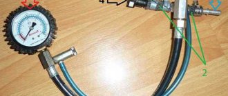
In the second picture you can see how the diode is installed, but with such a length of wiring it is not very convenient - everything is tight. It is better to make the length of the wire about 2 cm from the diode - this way, in my opinion, it will be easier to insert into the RN connector of the generator. As far as I remember, I have a K223 diode, i.e. it's silicon. Raises the voltage by about 1.3 V.
I’ll correct myself - I checked using reference data on the Internet what the K223 diode is - I must say that I was very mistaken in indicating exactly that name. In fact, there are diodes KD223 and D223, but their housings are completely different.
However, in the photos I provided, most likely diodes D214 or D242 are wrapped in electrical tape (there may be different letters after the numbers), here is the case (M6 thread):
Diode 242
I will briefly summarize the parameters here:
reverse voltage: from 50 to 100 V or higher forward current from 5 to 10A, with a voltage drop across the diode from 1 to 1.5 V.
Constant undercharging of the battery or its absolute discharge at the most inopportune moment is a headache for many car owners. One source of these problems may be the generator. But how to check it? Perhaps it's not his fault at all? Let's figure out together how much the generator must produce for the normal functioning of all car systems and maintaining the battery in a charged state.
How to check the operation of the generator
The battery in a car is an important element of the system, which is responsible for providing the car’s on-board network with electricity. The generator is used to charge the battery while it is active. Unstable operation of a device generating electricity causes a voltage drop in the network and failure to restore the capacity of the power source.
Normal generator performance means timely and complete replenishment of the battery charge level, which decreases under load. Checking the battery charge level from the generator is simple and can be done by the car owner himself.
Diagnostics of an automotive energy-generating device includes a visual inspection of the unit, its elements and related parts, as well as voltage and current measurements. At least twice a year, you should check the tension of the drive belt, excessive weakening of which leads to a decrease in the performance of the generator, and sometimes can lead to breakdown of the device. Once a year, you can check equipment elements - fasteners, diode bridge, voltage regulator and others. Timely maintenance of the battery will also guarantee the absence of problems - cleaning the terminals, adding distilled water.
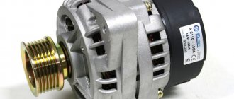
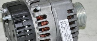
Purpose and principle of operation
Injection models VAZ-2107 are equipped with a generator type 37.3701. This device is superior in power to carburetor model generators.
Model 37.3701 amperage ranges from 80 to 90 amperes. This power is necessary for uninterrupted power supply to the entire electrical circuit, plus an additional load is provided. Unlike the carburetor model, the generator has to power a large number of sensors, the engine control unit, and a more powerful ignition module. The electrical circuit of an injection car includes a larger number of consumers.
A car generator is not much different from conventional stationary ones. It works on the principle of converting rotational energy into alternating electric current. Rotation is carried out by a transmission belt from the engine. The principle is as follows:
- After turning on the ignition, a current of 12 volts is supplied to the generator.
- This circuit includes a battery charge indicator lamp, which is installed on the dashboard. The lamp lights up after turning on the ignition.
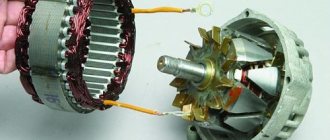
- As soon as the power unit starts working, the generator stator begins to rotate due to the belt, converting the magnetic field into electrical voltage.
- AC voltage passes through the diode bridge.
- The bridge converts alternating voltage to direct voltage.
- Electrical voltage is transmitted from the diode bridge to the brushes and the adjustment unit.
- The difference between the charging current and the battery voltage causes the warning lamp to go out.
What kind of charging should go to the battery from the generator?
It is traditionally believed that 13.5-14.5V should be supplied by the generator to the battery and this is absolutely enough to replenish the battery costs.
It is worth considering that using a battery with a higher power in a car than the manufacturer recommends also requires the installation of a more productive generating device.
It is necessary to take into account the load that the generator must withstand - it is calculated based on the maximum indicators of all electrical appliances and car systems.
Do not forget that the charging current from the energy-generating device will allow you to start the car in the cold season. In order to avoid problems with starting the car, we recommend purchasing generating equipment, the charge current of which will be approximately 10% of the capacity of the power source. That is, a battery of 100 A/h requires a generator that can produce 10A. Please note that for many cars, 100 amp equipment will operate at its maximum capacity, because the power consumption of the automotive system is in the region of 80 amps. Therefore, the choice of a source generating energy must take into account both the battery capacity and network consumption.
What's the result?
Taking into account the above information, it becomes clear that if problems begin with the battery, often the cause of the problem is the generator, and not the battery. In this case, the generator needs to be checked comprehensively (alternator brushes, slip rings, windings, generator relays, wiring, terminals, etc.)
Please note that too high a load on the generator (for example, when installing powerful emergency power consumers) in many cases causes rapid failure of the generator. To avoid problems (especially when choosing a new generator), you need to separately take into account some features.
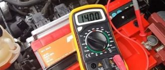
How to check the alternator voltage on the battery
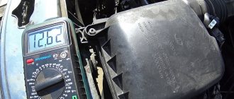
The potential difference can be diagnosed in two ways - directly at the generating equipment and through the battery. The generator is directly connected to the power source with a thick wire, therefore, to check the level of potential difference, you can measure the voltage at the power source. To do this, you will need special devices - a voltmeter, multimeter or load plug.
The wires of the first measuring instruments are connected to the battery in any sequence. The plug must be connected to the battery terminals with strict observance of polarity. It is generally accepted that the normal voltage in the network should not be lower than 12 volts. At idle speed without turning on all the electrical appliances of the car, this indicator should be at the level of 13.5-14V. A drop in voltage values to 13.3-13.8 volts is considered acceptable.
At the same time, using conventional testing equipment, you can check the resistance of the generator elements - rotor, stator and diode bridge. Diagnostics of rotary equipment is carried out by its winding. It is necessary to connect the probes of the device with slip rings. If the multimeter gives readings from 2, 3 to 5.1 ohms, then this element is working. The current consumption of the winding should be within 3-4.5 amperes.
Its normal resistance is 0.2 Ohm. The diode bridge is checked by the presence or absence of resistance, the indicators do not matter. The only thing worth considering is that there should not be a zero dimension. Measurements are carried out in pairs - positive output and all plates on this side or minus and all elements.
We remind you that for normal charging of a car battery, the voltage supplied by the generator must be from 13.5 to 14 volts.
Let's start the renovation
There may be several reasons for the battery not charging. The instructions below are quite universal and are suitable for any case.
Troubleshooting algorithm:
- First of all, we check the serviceability of the belt and its tension. If it is damaged or loose, charging will be less than normal and will ultimately lead to battery failure. The belt is also partly responsible for the operation of the cooling pump, so a damaged belt can cause other problems as well.
How many amperes does a car alternator produce per battery?
The current strength required by the electrical system of each car is individual and depends on the number of electricity consumers and their values. And also the charge current must be sufficient to charge the power source.
It is worth noting that ampere readings appear only when there is a load in the vehicle’s electrical system and, accordingly, the battery is discharged. After starting the car engine, the charging current is about 6-10 amperes and drops over time, because the battery is charging, taking on the main energy consumption. If you turn on additional equipment - headlights, radio or heated mirrors, you can see an increase in the charging current values.
When purchasing a generator, pay attention to its technical characteristics, which the manufacturer indicates on the case - that’s where you will find information about the maximum current that will flow to the battery.
In the table below you can see the approximate current values that the generator shows at different loads.
Table 1. How many amperes the generator produces under load.
What is on the VAZ 2110
For VAZ 2110 cars, the installation of two types of generators is provided, depending on the installed engine.
- For carburetor models, a generator with number 9402.3701 is installed.
- If the engine is injection, then the catalog number of the generator used will be 3202-3771. It has a serpentine belt.
Regardless of the type of installed engine and generator, respectively, problems with the devices are the same, therefore the inspection and repair procedure is identical in both cases.
Signs of a generator malfunction
In modern cars, breakdowns of the electrical system are one of the most common. A large number of electronics requires particularly careful monitoring of the operation and condition of the generator and battery, because their failure can immobilize the car. The most common signs of a generator malfunction are:
- battery indicator light on the instrument panel;
- unstable operation of the battery (its boiling over or undercharging);
- different intensity of headlights;
- extraneous sounds from the generator.
If you notice incorrect operation of the car, then perhaps the battery charging current from the generator is insufficient.
All malfunctions of electrical equipment, which includes the vehicle’s energy-generating device, are mechanical (deformation or breakage of fasteners, housing, malfunction of bearings, pressure springs, drive belt, etc.) or electrical (winding breaks, diode bridge malfunctions, burnout or wear of brushes , short circuits between turns, breakdowns, etc.).
Don’t write off a non-working generator: find out if there are repair kits and spare parts. Replace them if possible. If you cannot carry out repair work yourself, then take the generator to a workshop. Many craftsmen will be able to restore the unit at no extra cost and in the shortest possible time.
Reasons for failure
If the symptoms described below appear, carry out diagnostics. You can do it yourself or take the car to a car service. To determine the cause of the failure, special equipment is needed. If you decide to figure it out yourself, master a multimeter tester.
Five possible sources of difficulty are described below:
bearing wedge (lubricant is used up, sometimes the belt breaks - you will need to replace or rebuild the unit);
the winding has burned out (a common cause is the reagents used to treat winter roads);
brush wedge (cause - wear of graphite cores);
the regulator relay is faulty (this element prevents the battery from overcharging and stabilizes the voltage);
The diode bridge is broken.
Other causes of low voltage
A small potential difference in the system is not always associated with a breakdown of the generator or a bad battery. If the diagnosis of these elements does not reveal any problems, then you should pay attention to the following:
- condition of the battery terminals - connection density and oxidation;
- electrical wiring problems - oxidation, violation of its integrity;
- output contacts to electrical appliances;
- correctly selected energy consumers.
Each contact must be tightly adjacent and intact, that is, there must be no formations (for example, sulfation) that will disrupt the flow of current. Incorrect connection of contacts leads to accelerated battery discharge even when the car is not running.
To improve the connection of the elements of the car's electrical system, it is necessary to clean all contacts and restore the integrity of the wires by replacing them or connecting them and wrapping them with insulating tape.
In conclusion, I would like to repeat that stable operation of the car requires constant monitoring of all elements, and the generator should attract special attention. The battery is charged from it and provides electricity to the entire car system. Pay attention to all elements: generator brushes, slip rings, voltage regulator, equipment winding.
The most correct measurements should be carried out when the battery is fully charged and in various modes. Remember that the manufacturer links the characteristics of the generator to the number of engine revolutions - they help produce a certain current.
Detailed video on how to check the generator:
Do you have experience diagnosing an alternator and solving problems in a vehicle's electrical system? Please share your experience and opinion with our readers in the comments. If you have questions about the topics covered, we will be happy to answer them.
Many car owners are faced with a situation where, after starting the engine, the on-board computer or one of the devices begins to show that the battery is being recharged.
The consequences of this situation are very different and depend on how much the voltage in the on-board network exceeds the nominal one.
Slightly increased parameters will only negatively affect the battery (boiling of the electrolyte followed by its evaporation), but if the voltage coming from the generator greatly exceeds the norm, then electrical consumers may fail.
In any case, overcharging is a phenomenon that must be eliminated, otherwise it will not have the best effect on the service life of the battery and electrical appliances.
Types and location of voltage regulators
As you know, the VAZ 2107 car began to be produced a very long time ago. And over the years, not only different motors were installed on it, but also different voltage regulators. On the earliest models, the relay regulators were external. On later “sevens” the regulators were internal three-level. Let's take a closer look at these devices.
It is the external voltage regulator that many motorists in the old fashioned way call a “relay-regulator”. Today, external voltage regulators can only be seen on very old “Sevens” produced before 1995. These cars were equipped with an old generator model 37.3701, which was equipped with external relays.
External relay regulators were installed on the very first VAZ 2107 models
The external regulator was located under the hood of the car; it was mounted on the left front wheel arch of the car. As a rule, external relays were made on the basis of a single semiconductor, although after 1998 on some VAZ 2107 there were external regulators made on a common printed circuit board.
The external regulator was not built into the generator, but was located under the hood of the car
External relays had certain advantages:
- Replacing the external regulator was fairly easy. It was held on by only two bolts, which were not difficult to reach. The only mistake that a beginner could make when replacing this device is to mix up terminals 15 and 67 (they are located next to each other on the regulator);
- the cost of the external regulator was quite affordable, and they were sold in almost all car stores.
Of course, the device also had disadvantages:
- bulky design. Compared to later electronic regulators, the external relay seems very large and takes up too much engine compartment space;
- low reliability. External VAZ regulators have never been of high quality. It is difficult to say what is causing this: the low quality of individual components or the poor build quality of the device itself. But the fact remains a fact.
Internal three-level voltage regulators began to be installed on the VAZ 2107 starting in 1999.
The internal regulator began to be installed on the VAZ 2107 after 1999
These compact electronic devices were built directly into car generators.
The internal regulator is mounted directly into the VAZ 2107 generator
This technical solution had its advantages:
- compact sizes. Semiconductors were replaced by electronics, so now the voltage regulator fits in the palm of your hand;
- reliability. It’s simple: there’s nothing special about electronic devices that breaks. The only reason why a three-level regulator could burn out is a short circuit in the on-board network.
There are also disadvantages:
- difficulty of replacement. If there were no particular problems with external regulators, then to replace the internal relay the car owner first needs to get to the generator. To do this, he will have to remove the air filter and a couple of air ducts, which requires patience and time;
- difficulty of acquisition. As you know, the VAZ 2107 has long been out of production. So getting new components for the “seven” is becoming more and more difficult every year. Of course, this rule does not apply to all details. But internal three-level voltage regulators for the VAZ 2107 are among the parts that are not so easy to find today.
Battery charging circuit
For a general understanding of the reasons for overcharging, first consider the battery charging circuit diagram. And although it is structurally different on different cars, the general principle of construction is the same.
This circuit includes:
- Generator;
- Rectifier block (diode bridge);
- Relay regulator;
- Fuse box;
- Egnition lock;
- Charge indicator lamp;
- Battery
The recharging system works using the example of the VAZ 2106 and other cars from the VAZ classic series as follows: after starting the power plant, by means of a belt drive, the crankshaft begins to rotate the generator rotor, as a result of which this unit begins to generate electricity.
But since automobile generators use alternating current, the generated energy goes to the rectifier unit, where alternating current is converted into direct current.
After the rectifier unit, the electricity goes to the relay-regulator, whose task is to maintain the voltage in a given range.
After the regulator, the electrical energy passes through the circuit through the fuse box, the ignition switch and the charge indicator lamp, then returns to the output of the generator, and from there it is supplied to the battery.
The detailed diagram is shown below.
Purpose of the voltage regulator
The purpose of the voltage regulator is easy to guess from the name of this device. The regulator's task is to maintain the current coming from the generator at such a level that the voltage generated by the same generator is always kept within specified limits.
Modern voltage regulators on the VAZ 2107 are compact electronic devices
Features of the circuit
The above is a general diagram of the circuit, without details, but it is enough to understand how everything works. Now about the features of battery recharging.
The generator cannot independently regulate the parameters of the generated electricity, so the output voltage from it varies, and in a significant range, it depends on the crankshaft speed and the load in the on-board circuit. That is, the battery is essentially constantly being recharged while the generator is generating electricity.
In order for the battery to accept a charge, you need to apply a voltage to it slightly higher than the nominal value of the battery itself. The input voltage on the battery differs on different cars, but in general, this figure is in the range of 13.9-14.5 V.
It is at this voltage that the battery can “take” a charge. If the voltage is lower, the battery will be undercharged, and if the voltage is higher, it will be overcharged. Both situations have a negative impact on the battery.
The generator produces a voltage with a high value, and in order to maintain it in the circuit within the required limits, a relay regulator is included in the circuit.
On some models, this element is included in the design of the generator and is combined with a brush assembly (the most common design) or is a separate unit (found, for example, on the VAZ of the classic family).
Reasons for overcharging
A malfunction of the relay regulator is the most common cause of battery overcharging.
Due to a breakdown, this unit ceases to perform its functions and “passes” all the voltage generated by the generator into the on-board circuit, and it can reach 25 V. Naturally, not a single electrical appliance in a car is designed for such a voltage, so the elements of the on-board network begin to burn out .
Regulator failure can be partial or complete. In the first case, this element still performs its functions, but “passes” a voltage slightly higher than needed (for example, 15 V).
In this case, the overcharge of the battery can only be detected by readings from measuring instruments or the on-board computer. Electricity consumers practically do not “suffer” from such voltage, but even such an overcharge negatively affects the condition of the battery - with a constant process, the battery “boils out” and fails.
If the relay-regulator is completely malfunctioning, high readings (over 16 V) begin to damage consumers - light bulbs and fuses burn out first, then other devices. A significant excess of voltage can cause a fire in the electrical wiring.
Despite the fact that a partial breakdown of a relay does not pose a significant threat to the vehicle’s on-board network (with the exception of the battery), it should not be ignored, since at any moment it can develop into a complete failure of the element.
Since the relay-regulator is the only element that prevents the battery from overcharging, many car enthusiasts, when they detect increased voltage in the on-board network, immediately replace this unit.
But installing a new regulator does not always help; often the problem remains. Naturally, suspicion in this case falls on the generator. This unit can actually overcharge in the event of a breakdown of the diode bridge or a break in the windings, or a breakdown of the armature to the housing.
READ ON THE TOPIC: Car generator voltage, normal at idle and under load.
But if replacing the regulator relay does not help, you should not immediately change or send the generator for repair.
IMPORTANT: Often the reason for overcharging the battery lies in poor contact of the wiring of the battery charging system circuit (described above).
The reason is very simple: at the point where the contacts are oxidized, resistance arises, which the relay-regulator “perceives” as a load in the on-board network. For example, this can happen in the fuse box.
To compensate for it and prevent a drop in voltage, the regulator begins to “pass” large values, resulting in an increased voltage being supplied to the battery.
Therefore, in searching for the cause of battery overcharging, you should first check the relay-regulator, then the charging system circuit (all connections, as well as the fuse), and only after that remove and diagnose the generator.
No charging: signs and reasons
If the voltage from the generator for some reason stops supplying the battery, it will be discharged in a few days . And in the event of a complete failure of the battery installation, you will have to provide the entire on-board network, including the ignition system, yourself. So she can work for no more than an hour.
Signs of no charge
Symptoms that the alternator is not charging the battery include:
- a constantly burning or intermittently turning on warning light on the dashboard;
- rapid battery discharge;
- reduction in the performance of individual electrical devices on the machine's on-board network.
Signal lamp
There is a special lamp on the dashboard of the “Seven” that indicates that the battery is not charging. If the generator circuit is operating in normal mode, the lamp lights only when the ignition is on until the power unit starts operating. After starting the engine it should go out . If it continues to light, most likely the battery is not charging.
The first sign of a lack of battery charging is a constantly burning red lamp in the form of a battery.
It also happens that the control lamp turns on periodically. This is a sign that voltage is either not supplied to the battery at all, or is supplied inconsistently.
Battery drains quickly
If the generator or its circuit malfunctions, the battery will not receive the voltage necessary to charge it. In addition, she will have to power part of the car’s electrical equipment, consuming her own electricity. In such a situation, the battery will quickly run out. You will be able to understand this when difficulties arise in the process of starting the engine. Receiving insufficient energy, the starter will sluggishly turn the crankshaft flywheel or only “click” the traction relay.
Reduced electrical performance
Some electrical appliances will also help you understand that the generator is not operating normally. If you suspect a malfunction in the operation of the generator set, you can, for example, start the engine, turn on the headlights (if they have conventional incandescent or halogen lamps) and see how they shine . If the generator malfunctions, their brightness will be an order of magnitude lower, because the lamps are also designed for a certain rated current. A decrease in performance may also be observed at the heater fan. It will spin the blades noticeably worse. When it is turned on, the light from the headlights will be even weaker.
Reasons for lack of charging
There are few reasons for the battery not charging. These include:
- violation of the integrity (break) of the drive belt;
- belt loosening;
- a break in the wiring of the electrical circuit of the generator or severe oxidation of the connecting terminals;
- rectifier malfunctions;
- voltage regulator failure;
- a break in the generator windings or a short circuit.
Belt break
Although the belt is designed for 50 thousand km, it can break even after several days of use. Especially if there are defects in the pulleys of the device itself, the crankshaft or the pump. In itself, a break in the generator drive belt is not dangerous for the engine, but only if this malfunction is detected immediately. And the point here is not so much the lack of charging, but the pump stopping. If it stops working, the engine will instantly overheat. And this is already fraught with burnout of the cylinder head gasket with all the ensuing consequences. So if the warning light comes on or other symptoms of alternator malfunction occur, the first thing to do is check to see if the drive belt is intact. To do this, you need to stop the engine, open the hood and perform a visual inspection of the generator set drive.
If the belt breaks, not only the generator stops working, but also the pump.
Loosening the belt
The drive belt must have a certain tension. When the tension is weakened, it will slip on the crankshaft pulley, not providing the number of rotations of the generator rotor that is necessary to generate current with the required parameters. A sign of a loose belt is a characteristic whistle, which most often occurs when air humidity increases. When the belt slips, the warning light usually does not come on, but in some cases it may turn on for a while or blink.
If the generator belt tension is weak, it may slip on the pulley.
Open circuit and terminal oxidation
The battery will not charge even if the integrity of the wires in the generator connection circuit is damaged. The battery charging circuit is quite simple: just one wire connects the positive terminal of the battery to terminal “30” of the generator set. It is through this that the voltage is supplied. The battery negative is connected to ground, to which the generator housing and the corresponding winding terminals are also connected. You just need to check for contact between the indicated points in the circuit.
Oxidation of the battery terminals, as well as their unreliable connection to the wire tips, can also significantly affect the current supply . You can check the condition of the terminals visually, but you cannot determine how the current flows by eye. It is better to once again clean and retighten all wire connections on the battery and generator.
When the battery terminals oxidize, the contact deteriorates and the charging current stops flowing.
Failure of the rectifier module
If the rectifier breaks down, no current will flow from the generator to the battery. The block itself is a board with six silicon diodes (3 positive and 3 negative). If at least one of them burns out, the rectifier will need to be replaced, since it cannot be repaired.
The rectifier is designed to convert alternating current into direct current
Regulator failure
A stabilizer malfunction is characterized by a change in the characteristics of the current supplied to the battery. In other words, the charging voltage is supplied to the battery, but it is higher or lower than required. The regulator also cannot be repaired and must be replaced if it fails.
The relay regulator functions as a voltage stabilizer
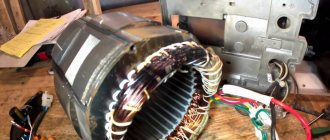
Malfunction of phase windings
If a break occurs in the windings, the generator stops performing its tasks. When an interturn short circuit occurs, the installation may behave differently. Typically, a sign of such a breakdown is a characteristic burning smell and a hum during operation. These two faults can only be diagnosed after removing the device from the car. Repairing a generator in the event of a break or short circuit involves replacing the burnt winding or stator assembly.
If there is a break or short circuit in the windings, the generator fails
Diagnostics of the relay regulator
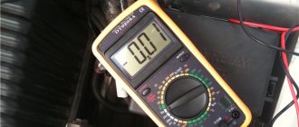
Checking the relay regulator when recharging the battery is not a complicated procedure and you can do it yourself using a multimeter.
The test comes down to measuring the voltage at the battery terminals under different operating modes of the power plant. That is, we simply connect the multimeter probes to the terminals and measure the voltage first at XX, then at medium speeds, and then at high speeds.
At idle, the normal voltage is 13.2-14.0 V, at medium speeds - 13.6-14.2 V, at high speeds - up to 14.5 V.
If the values exceed the specified values, you should check and clean the contacts of the charging system circuit and repeat the procedure again.
If cleaning does not help, we check the relay separately (removed from the car), but for this you will need a power source with regulated voltage (you can use a battery charger), as well as a regular 12 V lamp.
The essence of the test is this: we connect the negative wire from the charger to the housing, and connect the positive wire to the regulator terminal. The lamp is connected to graphite brushes (polarity is not important).
When checking, we first set the voltage at the source to 12.7 V, at which the lamp should light up. We gradually increase the value to 14.5 V. When the specified value is reached, a working regulator should operate and the lamp will go out.
If it continues to light when exceeding 14.5 V, then the unit is faulty and requires replacement.
Generator VAZ 2107 carburetor model G-222
| Position number on the diagram | Explanation of the position on the diagram |
| 1 | voltage regulator |
| 2 | cap on the contact side |
| 3 | rotor |
| 4 | drive side cover |
| 5 | pulley with blades |
| 6 | neutral wire connector |
| 7 | stud securing the generator to the tension plate |
| 8 | generator terminal 30 |
| 9 | voltage regulator housing |
| 10 | terminal 15 of the generator (pin B of the voltage regulator) |
| 11 | capacitor |
| 12 | lag bolt |
| 13 | stator |
| 14 | sleeve |
| 15 | buffer bushing |
| 16 | pressing bushing |
| 17 | rectifier unit |
| 18 | slip rings |
| 19 | rubber ring |
| 20 | brush holder |
Technical characteristics of the generator G-222
- Maximum recoil current (at 13 V and rotor speed 5000 min1), A 45
- Limits adjustable voltage, V 14.1 ±0.5
- Highest rotor speed, min-1 - 13000
- Motor-generator gear ratio 1:2.04
Generator diagram VAZ 2107 carburetor
| Position number on the diagram | Explanation of the position on the diagram |
| 1 | electricity storage |
| 2 | generator VAZ 2107 |
| 3 | battery charging light bulb |
| 4 | Relay and fuse block |
| 5 | ignition lock |
| 6 | battery charging warning light |
| 7 | voltmeter |
Layout of parts for generator G-222
| Position number on the diagram | Explanation of the position on the diagram |
| 1 | brush holder |
| 2 | neutral wire plug terminal block |
| 3 | contact bolt insulating inserts |
| 4 | rectifier unit |
| 5 | contact bolt |
| 6 | stator |
| 7 | rotor |
| 8 | washer |
| 9 | bearing inner washer |
| 10 | drive side cover |
| 11 | pulley |
| 12 | outer bearing mounting washer |
| 13 | pinch bolt |
| 14 | rotor bearing |
| 15 | pressing bushing |
| 16 | cap on the contact ring side |
| 17 | buffer insert |
| 18 | insert |
| 19 | capacitor |
| 20 | base |
| 21 | voltage regulator |
| 22 | frame |
How to check the VAZ 2107 generator carburetor
Scheme for testing the G-222 generator on a stand
| Position number on the diagram | Explanation of the position on the diagram |
| 1 | generator VAZ 2107 |
| 2 | voltmeter |
| 3 | ammeter |
| 4 | rheostat |
| 5 | switch |
| 6 | electricity storage |
Checking the generator relay 2107 carburetor brand G-222
Checking the relay of the generator G-222 VAZ 2107 is carried out according to the diagram shown below in the figure.
| Position number on the diagram | Explanation of the position on the diagram |
| 1 | current storage |
| 2 | contact "-" of the voltage regulator |
| 3 | voltage regulator |
| 4 | output "w" of the regulator |
| 5 | output "B" of the regulator |
| 6 | signal light |
| 7 | contact "B" of the regulator |
Above is a diagram of testing the voltage relay removed from the generator.
Checking the voltage regulator of the G-222 generator of a carburetor engine is similar to checking the voltage regulator of the 37.3701 generator of an injection engine.
The generator relay is checked in the following sequence:
- A 1 - 3 W light bulb is connected to contacts “W” and “B”;
- A source of electricity is connected to terminals “B”, “B” and to the relay ground. First with a voltage of 12 V, and then 15 - 16 V.
- If the regulator is working properly, then in the first case the light should light up, and in the 2nd case it should go out. If the light bulb lights up in two ways, then there is a breakdown in the regulator. When the light does not light in two cases, there is a break or there is no contact between the brushes and the terminals of the regulator.
Circuits for testing rectifier valves
| Position number on the diagram | Explanation of the position on the diagram |
| 1 | voltage regulator |
| 2 | generator rotor |
| 3 | stator winding |
| 4 | rectifier valves |
| 5 | capacitor for protection against overloads and radio interference |
| 6 | signal light |
| 7 | current storage |
| I | control of “+” and “-” valves at once |
| II | control of negative valves |
| III | control of positive valves |
For ease of fastening of rectifier parts, 3 valves have a “+” of rectified voltage on the body. These are “positive” valves, and they are pressed into one plate of the rectifier block. The other 3 valves - “negative” - have a “-” rectified voltage on the body and are pressed into another plate of the rectifier block.
The operating valve allows electricity to flow in one direction. Broken - may not pass current (open circuit) or pass current in both directions (short).
You can check with an ohmmeter or using a 25...40 W light bulb and a battery. First, we check whether there is a short in the “plus” and “minus” valves at once. To do this, connect the “+” of the battery through a light bulb to contact “30” of the generator, and “-” to the generator housing. When the light is on, it means that both the “minus” and “plus” valves have a short one.
The short of the “-” valves can be checked by connecting the “+” of the current source through a light bulb with the terminal block of the neutral wire of the stator winding, and the “-” - with the generator housing. The glow of the light bulb shows a shortness in 1 or several “negative” valves, while the glow of the light bulb may be a consequence of the shortness of the turns of the stator winding on the generator housing. Such a breakdown is less common than short valves. To control the short in the “positive” valves, connect “+” of the battery through a light bulb to terminal “30” of the generator, and “-” to the terminal block of the neutral wire of the stator winding (Fig. III). The glow of the light bulb indicates the shortness of 1 or several “positive” valves.
Mounting the generator 2107 carburetor
| Item number in the picture | Explanation of the position in the figure | detail number |
| 1 | conical spring washer 10 | 00001-0011983-73 |
| 2 | Nut M10x1.25 | 00001-0021647-11 |
| 3 | Nut M10x1.25 self-locking | 00001-0025745-11 |
| 4 | washer | 21010-3701490-00 |
| 5 | bar | 21010-3701635-00 |
| 6 | generator vaz 2107 carburetor | 21080-3701010-00, 21080-3701010-01, 21080-3701010-05 |
| 7 | Bolt M12x1.25x120 | 00001-0055418-21 |
| 8 | Hairpin M10x1.25x20 | 00001-0035461-21 |
| 9 | washer 12 | 00001-0005200-01 |
| 10 | engraver | 00001-0005170-70 |
| 11 | Nut M12x1.25 | 00001-0061015-11 |
| 12 | Bolt M10x1.25x20 | 00001-0059705-21 |
| 13 | bracket | 21050-3701630-00 |
| 14 | Bolt M10x1.25x40 | 00001-0013070-21 |