The most astute car enthusiasts have long noticed that on some car models there is such an option as turning on the fog lights when you turn the steering wheel. That is, you turn right, the right fog light comes on. Turn left - left. How justified and practical this option is is debatable! However, it looks very solid and attractive. In addition, such options are complemented by cars in the premium segment, which means that those whose cars do not live up to this would really like to have something similar. Well, if you want it and also really need it, then why not! Moreover, we will now discuss the technical issues of how to implement this and what needs to be done.
Mechanical improvements to turn on fog lights when turning the steering wheel
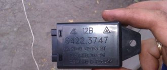
Implementing this project option will require work on several fronts. After all, here it will be necessary to detect the position of the steering wheel relative to its “straight” direction, and also turn on and off the fog lights. It is precisely the basing of the steering wheel relative to its location that will be ensured by the mechanical-electrical part, and the activation exclusively by the electrical part. When describing the mechanical part, we will once again describe the problem to be solved. It seems like a simple task, I turned the steering wheel and the headlight turned on. However, the steering wheel has 3-3.5 turns from one extreme to the other. Moreover, turning the steering wheel back and turning on the opposite headlight should occur only after returning to that same “neutral” and “direct” state, and only after turning in the opposite direction should the headlight light up. In general, you won’t be able to get by with two buttons or reed switches here. As a result, you can implement such a “snail”
This is a ring on which a spring from an old mechanical watch is attached. In this case, the spring plate separates the light source and the photocell. As soon as the light hits the photocell, the circuit that controls the fog lamp is turned on. Imagine what will happen if you turn such a ring in one direction and the other... So, everything is clear with this. How to implement this in theory is also clear. In practice it will look something like this.
Assembly instructions
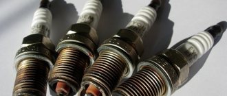
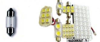
LED lamps are semiconductor elements that glow when exposed to electric current.
The main element in them is silicon. Depending on what impurities are used, the color of the light bulbs changes.
Photo gallery “Possible options for dynamic direction indicators”
Tools and materials
To make a running turn signal with your own hands, you will need the following tools:
- soldering iron;
- side cutters or pliers;
- soldering iron and soldering material;
- tester.
You need to prepare fiberglass laminate from consumables. It is needed for the manufacture of a printed circuit board on which the semiconductor element will be placed. The required LEDs are selected. Depending on the characteristics of the LEDs and the current and voltage values of the on-board network, the characteristics of the protective resistors are calculated. Using calculations, the remaining components of the network are selected (the author of the video is Evgeny Zadvornov).
Work sequence
Before making turn signals, you need to choose a suitable scheme.
Then, based on the diagram, make a printed circuit board and apply markings on it to place future elements.
The assembly consists of a sequence of actions:
- First, you should turn off the power to the car by disconnecting the negative terminal from the battery.
- Next, you need to remove the old turn signals and carefully disassemble them.
- Old light bulbs should be unscrewed.
- The joints should be cleaned of glue, degreased, washed and allowed to dry.
- In place of each old element, a new running light turn signal is installed.
- Next, assembly and installation of the lights is done in the reverse order.
- After installation, the wires are connected.
At the next stage, an additional stabilized power source is connected to the network. Its input receives power from the intermediate relay, and the output is connected to a diode. It is better to place it in the instrument panel.
When connecting LEDs, you must ensure that the anode is connected to the plus of the power source, and the cathode to the minus. If the connection is not made correctly, the semiconductor elements will not light up and may even burn out.
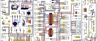
Electrical circuit for turning on the fog lights when turning the steering wheel
The electrical part can be thought of as a light sensor. After all, in fact, when a signal appears on the photocell, the headlight should light up. That is, the signal from the photocell, no matter what kind of element it is, a photoresistor or a photodiode or something else, is the control signal for the power currents supplying the fog lamp. We can bring to your attention several different circuits, say, on the NE555 chip... Or, even simpler, on a pair of transistors. What is even simpler, but also effective.
That is, I implement the mechanical part that we described in the previous paragraph and by connecting to the photocell, which is part of the second part, we thereby implement the project of turning the fog lights on and off by turning the steering wheel
What are the benefits of installing DRLs in turn signals?
Using a separate daylight illumination saves a lot of battery energy, and this is the main advantage of this solution. It consumes a maximum of 15 W, versus about 100 W for the headlights, and this is a very noticeable difference. The battery holds its charge longer, the generator charges it faster, and in general its capacity drops longer, that is, its service life is extended.
A side effect of less load on the generator is reduced fuel consumption. And this is direct monetary savings. Considering that installing running lights is relatively inexpensive, it will quickly pay for itself due to the saved gasoline.
Features of using the scheme for turning on and off PTF when turning the steering wheel
We do not want to talk about the pragmatism of such illumination, because this is an individual and conscious decision of each of us. But we will still give some tips on how to implement all of the above. Firstly, about the mechanical part. Here you should choose the shape of the spring so that the headlights turn on at least when the steering wheel is turned 45-60 degrees to one side. You should not do it as shown in the diagram or in the photo. Otherwise, when driving the car, the fog lights will switch so often, even when steering, that it will not be an option, but a toy. Secondly, the lifespan of standard halogen lamps can be significantly reduced due to such a game of switching on and off. There are two ways to solve this problem. First, install high-quality LED lamps. Second, set up a smooth ignition mode, preferably with PWM. This will save lamps and power consumption. Third, be sure to use a light sensor that will limit the operation of fog lights during daylight hours or a control signal from the dimensions, as in our case. Then during the day this option will not work, which means you will seriously save on burnt out light bulbs and their “empty” operation during the daytime.
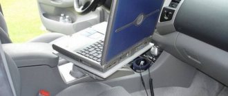
Via PC
- Lada Vesta or Lada XRAY car with a light sensor.
- Adapter ELM327, you can buy on AliExpress (see product catalog).
- Ddt4all software (download).
How to activate the function
:
- Run ddt4all. Select a port. Select an adapter. Check the box and click Connect.
- In the window that opens, click the button marked with a circle (with a magnifying glass).
- Select search by CAN.
- Find and select the [EMM] block.
- Open the EMM_Cornering - Configuration item below.
- A menu should open.
- Change the value of Nbx_Cornering_CF in the WRITE field from 0 to 1.
- Turn on the Expert mode (in the menu at the top, second icon from the left) and press the Send button (right).
- In the READ field the value should change to 1. The value 40 in the READ field of the Cxx_CorneringSpeed_CF function means that the cornering illumination function will work up to 40 km/h (can be changed as desired, also using the Send button).
The process is also shown in the video:
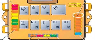
Electronic control unit (JBE)
JBE is responsible for power supply. JBE is connected to FRM via K-CAN bus. JBE is located under the instrument panel in the front passenger footwell.
Fog lamp diagram for E70
| Index | Explanation | Index | Explanation |
| 1 | Cornering light reflector | 2 | Fog light reflector |
| 3 | Fog lamp |
| Index | Explanation | Index | Explanation |
| 1 | Left Stepper Motor Controller (SMC) | 2 | Left main headlight |
| 3 | Left xenon headlight ECU | 4 | Left fog lamp |
| 5 | right fog light | 6 | Right xenon headlight control unit |
| 7 | Right main headlight | 8 | Right Stepper Motor Controller (SMC) |
| 9 | Steering column switch center (SZL) | 10 | Electronic control unit (JBE) |
| 11 | Footwell module (FRM) | 12 | Function center in the roof (FZD) |
| 13 | Rain, Light and Sun Sensor (RLSS) | 14 | Light switch |
Recommendations
Comments 30
After 30k of mileage both burned out, the dealer decided to change the first one at the same time as the maintenance, wow the price for a lamp (1 piece) - 990 rubles and a replacement 1000 rubles. I bought the same size in a nearby store, they gave me a choice, for 120 rubles or 180. Of course, 180! I installed it myself, it took 3 minutes, it’s been burning for 1.5 years and the color is no different from the original) 180 rubles versus 2000. You can save money on such things)!
Maya, what kind of original lamp was there, maybe you remember the manufacturer/code/model, it also burned out and also the left one.
Unfortunately, I didn’t pay attention to this and didn’t record her article number anywhere (
Maya, what kind of original lamp was there, maybe you remember the manufacturer/code/model, it also burned out and also the left one.
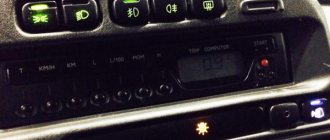
Activating the cornering lights
The side from which the cornering lights turn on depends on the following conditions: Direction of travel forward
- speed less than 40 km/h
- turn signal on
- turn signal side
- speed less than 40 km/h
- steering wheel turn
- side in the direction of steering wheel rotation
Reversing
- speed less than 40 km/h
- reverse gear engaged
- turn signal on
- turn signal side
- speed less than 40 km/h
- reverse gear engaged
- steering wheel turn
- the side opposite to the direction of rotation of the steering wheel
US version only:
- speed less than 65 km/h
- reverse gear engaged
- both sides
Choosing the right daytime running lights
In order to choose the right daytime running lights for the VAZ 2114, first of all you need to know the requirements that are imposed on them in the traffic rules, because their installation should not negatively affect traffic safety.
The requirements for running lights of the VAZ 2114 are as follows:
- Form. The shape of the VAZ 2114 headlights is not regulated in any way, but there is a required area of the reflective surface, it must be equal to 40 cm2 or more. For rectangular ones, it is easy to measure; for round ones, the diameter should be more than 50 mm.
- The power of light. GOST has a certain value for the luminous intensity of the DRL; measuring it yourself is not difficult; for this you only need a lux meter. It’s almost impossible to feel the difference “by eye” in a store, but during the day, on the road, the difference will be colossal. As a rule, cheap VAZ 2114 headlights do not reach the required parameters, since they use low-power LEDs. The power of LEDs can be determined by the housing in which they are installed. Weak diodes are usually sold in a plastic case, but good, powerful ones are sold in a metal case.
- Rules for attaching to a car. The mounting location is also specifically stated in GOST. DRL lights should not be mounted further than 40 cm from the edge of the body and closer than 60 cm from each other. The mounting height from the ground is not so rigid; you can attach the DRL anywhere, in the front of the car, but it should not create any glare.
Different running lights have different mounting methods, and when choosing DRLs for a VAZ 2114, you should not forget about this.
Daytime running lights can be attached to:
- self-tapping screws;
- screeds;
- Velcro.
Self-tapping screws and zip ties are, of course, much more reliable than Velcro, but if you don’t want to drill into the bumper or there are no grooves in the grille onto which you can attach the zip ties, Velcro is the only way out.
Equipment and technical characteristics
For the convenience of customers, caring manufacturers have assembled a full-fledged RunLed set. It includes the following necessary elements:
- Multifunctional LED strip (made of non-toxic silicone);
- RGB backlight control unit (gives red, green and blue colors);
- Super double-sided tape;
- Instructions with illustrations;
Read more: VAZ 2101 interior, re-tensioning seat belts, which seats to install, instructions with photos and videos
The manual describes all possible operating modes of the device: alarm during an accident, brake light, left/right turns and backlight while driving. There is also a wiring diagram there.
RunLed turn signals operate at a mains voltage of 12 volts. The backlight power is 16 Watts. The device functions smoothly in extreme temperatures such as -40°, 60° and everything in between. RunLed products are reliably protected from aggressive environments by several layers of polymer. The manufacturer guarantees these technical characteristics with a 1-year warranty.
Controller firmware
To work with pixel LEDs you will need a library. You can install it as follows: Sketch -> Connect library -> Manage libraries. Next, enter the name of the library Adafruit_NeoPixel.h in the search menu and click the install button. After that, insert the sketch into the program and replace the number of LEDs in the code (we use 22 diodes):
#include // include the Adafruit_NeoPixel library strip = Adafruit_NeoPixel(22, 8, NEO_GRB + NEO_KHZ800); int t,t1,t2,t3,t4,p2,p1 = 0;// time variable void setup() { pinMode(2, INPUT); pinMode(3, INPUT); pinMode(4, INPUT); digitalWrite(2, LOW); digitalWrite(3, LOW); digitalWrite(4, LOW);
strip.begin(); strip.show();
} void loop() { if (digitalRead(2) == LOW) { //If the turn signal is off for(int i = 0; i strip.setPixelColor(i, strip.Color(255,255,255)); // R=255, G=255, B=255 — white color of the LED; when turned on, we turn on the running lights } strip.show(); }
if ((digitalRead(2) == HIGH) & (t == 1)) { // check if the turn signal is turned on for(int i = 0; i strip.setPixelColor(i, strip.Color(0, 0, 0) ); // extinguish all diodes } strip.show(); for(int k = 0; k
for(int i = 0; i
if (digitalRead(2) == HIGH) {k = 0;} // if while the turn signal is blinking we receive another positive signal, then reset the counter so that the turn signal flashes at least 3 more times strip.setPixelColor(i, strip.Color( 255, 69, 0)); // R=255, G=69, B=0 - LED color
delay((t4)/22); strip.show();
} if (digitalRead(2) == HIGH) {t4=t4+20;} // if all the diodes are lit yellow, but the signal from the relay is still going, then we increase the burning time if (digitalRead(2) == LOW) {t4 =t4-20;} // if all the diodes are lit yellow, but the signal from the relay is still coming, then we increase the burning time
for(int i = 0; i
strip.setPixelColor(i, strip.Color(0, 0, 0)); // R=0, G=0, B=0 - LED color
delay((t3)/22); strip.show();
} if ((digitalRead(2) == LOW)) {t3=t3+20;} if ((digitalRead(2) == HIGH)) {t3=t3-20;} }
if ((digitalRead(2) == HIGH) & (t == 0)) { // check if the turn signal is on
t1 = millis(); //remember what time it turned on for(int i = 0; i strip.setPixelColor(i, strip.Color(255, 69, 0)); // when you turn on the turn signal for the first time, turn on all the diodes yellow } strip.show(); while (digitalRead(2) == HIGH) {} t2 = millis(); // remember what time the turn signal turned off t4=t2-t1;
for(int i = 0; i strip.setPixelColor(i, strip.Color(0, 0, 0)); // turn off the diodes when the signal from the turn relay is lost } strip.show(); while (digitalRead(2) == LOW) { if ((millis()-t2)>2000){break;} } if ((millis()-t2) t3 = millis()-t2; // time for which the turn signals go out t = 1; // flag, we know that the time value has been saved. } }
if (digitalRead(4) == HIGH) { //special signals for(int j = 0; j for(int i = 0; i strip.setPixelColor(i, strip.Color(255, 0, 0)); // R=255, G=0, B=0 — LED color } strip.show(); delay(20); for(int i = 0; i
} strip.show(); delay(20); }
for(int j = 0; j for(int i = 0; i strip.setPixelColor(i, strip.Color(0, 0, 255)); // R=0, G=0, B=255 — LED color } strip.show(); delay(20); for(int i = 0; i strip.setPixelColor(i, strip.Color(0, 0, 0)); // R=0, G=0, B= 0 — LED color } strip.show(); delay(20); } }
if (digitalRead(3) == HIGH) { //strobe for(int j = 0; j for(int i = 0; i strip.setPixelColor(i, strip.Color(255, 255, 255)); // R=255, G=255, B=255 — LED color } strip.show();
delay(15); for(int i = 0; i strip.setPixelColor(i, strip.Color(0, 0, 0)); // R=0, G=0, B=0 — LED color } strip.show(); delay (15);} delay(500);
Do the same for the code for the second turn signal.
Connection diagram
The Arduino controller must be connected to the car's network via a 12V -> 5V converter so that the voltage to the circuit comes from turning on the ignition. You need to connect the positive wire from the existing turn signal to the KREN5V voltage stabilizer. This article discusses the connection and firmware of only one turn signal; to make a second turn signal, you need to similarly connect the second LED strip to any free digital output of the Arduino (for example 7), and also add the code for it in the firmware according to our example.