Very often, weather conditions on the road develop in such a way (for example, with light drizzle) that there is a need for intermittent operation of the windshield wiper blades. In such situations, many motorists understand how convenient it is to have a windshield wiper relay with an adjustable pause on their car. Thanks to this design, driving comfort is significantly improved. We will talk about the need for such a relay, how to use it and whether it can be installed on your car if it doesn’t already exist in this article.
Windshield wiper relay with adjustable pause
Very often, weather conditions on the road develop in such a way (for example, with light drizzle) that there is a need for intermittent operation of the windshield wiper blades. In such situations, many motorists understand how convenient it is to have a windshield wiper relay with an adjustable pause on their car. Thanks to this design, driving comfort is significantly improved. We will talk about the need for such a relay, how to use it and whether it can be installed on your car if it doesn’t already exist in this article.
Lada 2107 Made in the USSR › Logbook › Electronic windshield wiper relay for Zhiguli Hand made
I got tired of my windshield wiper relay on a bimetallic plate and started looking on the net for who had changed what.
The search did not last long and I found an article of the same name which I will post below. Auto electronics → Electronic windshield wiper relay for Zhiguli
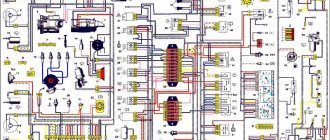
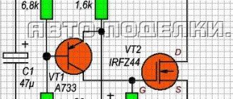
To this day, Zhiguli cars remain the most common “foreign car” running on our roads for many years. There are especially many “old ladies” VAZ 2101-2107 models. Over the course of its 30 years, my “two” has changed more than one owner. Many components and parts were replaced. If this can be understood from the hardware, then the repeated failure of the RS514 windshield wiper relay and the PP380 relay-regulator required the refusal of their services. An analysis of amateur radio literature over the past 20 years has shown a tendency to replace PC514 relays with electronic devices. At first these were transistor multivibrators. An electromagnetic relay or a powerful transistor was installed as a load in one of the arms. Then they began to use a thyristor as a key. The simplest windshield wiper relay circuit [1] contains a KU201 thyristor and one low-power transistor. The duration of the pause in the wiper cycle depends on the discharge time of the timing capacitor, and it can be adjusted. This is good, since such a need appears when the intensity of rain or snow changes. But the fact that this simplest circuit is very critical to the parameters of the thyristor and requires painstaking selection of many elements is certainly bad. Adding another transistor [2] eliminates the selection of elements. The proposed circuit of the electronic windshield wiper relay (Fig. 1) is more complex in just a few elements, but has higher operational reliability and can provide dynamic engine braking. No modifications to the standard electrical circuit of the vehicle [3] are required.
The actual windshield wiper relay circuit, highlighted in Fig. 1 by a dash-dot line, is mounted on a printed circuit board (Fig. 2 and 3) made of foil fiberglass and placed in the housing of the dismantled PC514 relay. The XR1 connector plug along with the connecting wires are also from the PC514 relay.
The device works as follows. The standard dual key switch SB1 of the windshield wiper operating modes has three positions: “O” - the windshield wiper is off; I — cyclic (with pause) operating mode; II - continuous operating mode of the windshield wiper. In position II, power (+12 V) is supplied directly to the wiper motor winding M1 through the int contact of connector XR2. In this case, limit switch SB2 does not affect the operation of the engine. In position I of the operating mode switch SB1, +12 V voltages are supplied to pin 3 of the electronic relay circuit. This state of SB1 is shown in the drawing. Since capacitor C1 is initially discharged, there is no voltage at the base of transistor VT1 relative to its emitter, and VT1 is locked. In this case, transistor VT2 is unlocked by the base current through resistor R5 and motor winding M1. Accordingly, thyristor VS1 is unlocked, receiving a positive potential to the control electrode through resistor R7. The thyristor instantly goes into a conducting state and “remembers” it. Through terminal 4 of the electronic relay circuit, +12 V is supplied to the motor winding, and the windshield wiper begins to move the blades. Limit switch SB2 switches almost simultaneously. In this case, the thyristor VS1 is short-circuited by its “int-C” contacts (connector XR2) and goes into a non-conducting state, but the supply voltage to the motor does not stop. Through resistor R6, transistor VT3 is unlocked, providing fast charging to the voltage of the power supply of capacitor C1 through resistor R4, unlocking transistor VT1 through resistor R3. This in turn leads to the blocking of transistor VT2. After the brushes make a double stroke and return to their original position, the state of the limit switch SB2 changes, the “int-C” contacts open, and the “int-F” contacts close. Motor M1 stops because thyristor VS1 is in a non-conducting state. VT3 is locked. A pause in the wiper cycle begins to form. Capacitor C1 is discharged through resistors R1, R2, R3 and the base junction of transistor VT1. The discharge (pause) time can be adjusted from 0.5 to 20 with potentiometer R1. A decrease in the charge of C1 leads to the turning off of transistor VT1. Transistor VT2 and thyristor VS1 are unlocked accordingly. The motor is supplied with supply voltage through thyristor VS1, and after a very short period of time, power is supplied by limit switch SB2. The process of moving the brushes is repeated. Capacitor C2 reduces sparking of contacts SB2 of the limit switch and interference with the operation of the windshield wiper relay in the car. Its value is not critical; it can be reduced by 10 times. Protective diode VD2. It can be replaced by KD105, KD221, KD208, KD209 and similar ones. As VS1, you can use KU202 thyristors with any letter. The use of KU201 is possible, but the reliability of operation will be lower. The printed circuit board allows the use of thyristors in a plastic case of type KU202N-1 or T106-10. In this case, the printed circuit board can be shortened by 15 mm. The maximum pause duration can be increased if desired. To do this, it is enough to proportionally increase the resistance of the potentiometer R1 or the capacitance of the capacitor C1. Now a few words about dynamic engine braking. The fact is that the drive mechanism of the windshield wiper blades of Zhiguli cars has small friction losses. If to stop the engine you use only de-energizing the engine in the initial extreme position of the brushes, then by inertia the engine rotor will rotate a little more, and the brushes will advance an additional 3-5 mm. In principle, this does not create any particular inconvenience for the driver, but this disadvantage is easy to get rid of. In the standard design with the PC514 relay, the “int-F” contacts of the limit switch were used for this, which short-circuited the winding of the de-energized motor during a pause. In the proposed electronic relay circuit for dynamic braking of the engine, it is enough to install resistor R9. Its value is non-critical from 4.7 to 10 ohms. In fact, little power is dissipated on the resistor, since current flows through it during normal operation of the relay only for a short time, but an emergency condition of the windshield wiper cannot be ruled out, for example, “sticking” of the “int-F” contacts of the limit switch. Therefore, it is advisable to use a powerful resistor of the PEV-10 type. As mentioned earlier, the use of an electronic windshield wiper relay does not require changes to the standard wiring diagram of the Zhiguli car. A failed PC514 relay should be disassembled and a harness of four wires with a connector plug should be unsoldered from it. The colors of the wires and their connection to the plug are shown in Fig. 4.
If dynamic braking is not used, and this is quite justified to simplify the design, then the end of the unused wire should be insulated. The wires of the harness are soldered to the electronic relay board, and the board itself is placed in the PC514 case and covered with an insulating bottom lid that fits the size of the board. Potentiometer R1 is placed in any place convenient for the driver on the car panel, for example, near the windshield wiper operating mode switch. More than five copies of the electronic windshield wiper relay were manufactured and installed on cars. There was no selection of elements. All drivers report a wide range of pause intervals. The operation of the windshield wiper motor has become more stable. In conclusion, it should be noted that the proposed electronic relay is the simplest technological solution to the problem, therefore, the digital relay circuits found in the literature were not considered unnecessarily complicated, especially since neither the exact value of the pause nor its stability is unimportant for the driver. EL. Yakovlev, Uzhgorod References 1. Bornovolokov E.P., Frolov, V.V. Amateur radio circuits. - K.: Tekhtka, 1979. 2. Radio, television, electronics. Bulgaria - 1979. - No. 11. 3. Litvinenko V.V. Electrical equipment of VAZ cars // Zarulem. - 1997.- P.108-109.
What is the advantage of a relay with an adjustable pause
As a rule, all modern cars have at least 2 operating modes for windshield wipers: intermittent (that is, with a pause between sweeps of the blades) and constant. Have you ever encountered a situation where, during light drizzling rain, when the windshield wipers operate in the “pause” mode, this pause is too short and the wipers “scrape” on the windshield that has not yet gotten wet? I think most drivers have found themselves in similar situations. If your car does not have the ability to adjust the pause in the operation of the brushes, there are only two ways to solve the above problem. The first is to turn the wipers on and off as needed, but this distracts the driver from driving and creates additional risks for safe driving, especially if the trip is long. The second way is to leave everything as is, that is, to accept the movement of the brushes on dry glass, but this, firstly, leads to increased wear of the wiper cleaning tape, and secondly, it can irritate the driver.
A windshield wiper relay with an adjustable pause allows, by maintaining the required pause between sweeps of the wipers, to easily and most effectively solve the above problem, making travel in light rain conditions more comfortable.
There are two types of such relays:
- with several preset intervals between strokes (for example: 1, 2,4,8, 10 seconds, the driver can only choose the interval most suitable for current conditions;
- with the ability to set any required interval, i.e. Based on current conditions, the driver can set almost any interval using a certain algorithm.
conclusions
In our opinion, the ability to adjust the pause between strokes of the windshield wiper blades depending on the driving situation is not just a whim. This directly affects traffic safety. It’s not for nothing that almost all modern cars are equipped with this useful feature. If your car does not have such a relay, we advise you to try to select a ready-made solution from the modified windshield wiper relays offered on the auto parts market with the ability to set the required pause. Everyone who has modified their car in this way is usually satisfied with the result.
Found an inaccuracy in the article? Do you have anything to add? Please write to us about it in the comments.
How to install a variable pause wiper relay
Having appreciated all the advantages of a relay with pause adjustment, many motorists are wondering how to install it on their car and is it even possible? There are three ways to add this feature if your vehicle doesn't have it.
Selection of necessary parts from the same machine, but in a more “rich” configuration.
Often on foreign cars in the simplest equipment there is no windshield wiper pause adjustment, but this function appears in other equipment. Most often, it is enough to change the windshield wiper relay and steering column switch, and not necessarily with new ones. You can pick up the necessary parts at a dismantling shop.
Replacing the installed relay with a relay with an adjustable pause.
On the secondary market, there are quite a lot of ready-made solutions for replacing the standard windshield wiper relay, modified, with the ability to set a pause between sweeps of the blades within a fairly wide range (for example, from 0.5 to 45 seconds). Moreover, the advantages of this solution include the fact that the installation of such a relay is carried out in a standard place and does not require modification of the wiring or alteration of the steering column switches. True, most often such offers are designed for domestic cars.
Here are several options for such relays indicating their applicability and part numbers:
Manufactured by Russian Partner LLC
How to install a variable pause wiper relay
- RELAY 39.3777-03 is suitable for VAZ 2110, 2111, 2112 cars; VAZ 2108, 2109 (with the “old!” fuse block); VAZ 2123 Chevy-Niva; AZLK 2141, Svyatogor; IZH 2126 (ODA) with “old!” fuse box; UAZ 3160.
- RELAY 54.3777 is suitable for VAZ 2113, 2114, 2115; VAZ 2108, 2109 with “new!” fuse box (blade type fuses); VAZ 1117, 1118, 1119 ( Kalina ); VAZ 2170, 2171, 2172 ( Priora ); GAZ 3111; IZH 2126 (ODA) with “new!” fuse block. In addition, relay 54.3777 is suitable for some foreign cars, as it has a “European” arrangement of contacts. The possibility of using a relay depends on the specific car model.
- RELAY 39.3777-02 for GAS cars: GAZELLE; BARGUZIN; SABLE; GAZ 31105; UAZ 31514 and 31519 since 1998;
Manufactured by Energomash CJSC
Windshield wiper relay with adjustable pause manufactured by Energomash CJSC
- 72.3777-01 For cars “Gazelle”, “Sable”;
- 721.3777-01 For Volga cars 3102, 3110;
- 722.3777-02 For VAZ-2101, -2102, -2103, -2104, -2105, -2106, -2107, Niva cars
- 723.3777-01 For cars VAZ-2108, -2109, -2113, -2114, -2115, -11183 (Lada-Kalina), IZH 2126;
- 723.3777-05 with rain sensor For VAZ-2113, -2114, -2115, -2170, Lada Kalina. GAZ 3111; VAZ-2108, -2109, -2110, IZH 2126 (with a new fuse block); foreign cars (with a similar arrangement of relay contacts);
- 724.3777-01 For cars VAZ-2108, -2109, -2110, IZH 2126 (old fuse box), AZLK 2141, UAZ 3160, Niva Chevrolet
Windshield washer does not function
Since not only the cleaner, but also the washer is responsible for the cleanliness of the windshield, it is worth considering the malfunctions of this device. The design of the mechanism consists of the following elements:
- washer pump;
- fluid reservoir;
- nozzles (jet);
- auxiliary parts (wiring, tubes).
The washer reservoir is located in the engine compartment and is held on a special bracket. Water or a special glass cleaning liquid is poured into it. The tank also contains a pump, through which the liquid is supplied through tubes to the nozzles, which spray it over the surface of the glass.
The washer reservoir is located under the hood, and a pump is installed inside the tank
Despite its simple design, the washer also sometimes fails and there may be several reasons for this:
- pump failure;
- fuse blown;
- kinking of tubes;
- breakdown of the steering column switch;
- poor contact on the power supply circuit.
Pump check
The washer pump on Zhiguli cars often does not work due to poor contact on the electric motor itself or wear of the plastic elements of the device. Checking the serviceability of the electric motor is quite simple. To do this, open the hood and pull the washer lever on the steering column switch. If the mechanism does not make any sounds, then the cause should be sought in the power circuit or in the pump itself. If the motor hums and fluid is not supplied, then most likely a tube has fallen off the fitting inside the tank or the tubes supplying fluid to the injectors have become bent.
A multimeter will also help you verify whether the pump is working or not. Using the probes of the device, we touch the washer contacts when the latter is turned on. The presence of voltage and the absence of “signs of life” of the motor will indicate its malfunction. Sometimes it happens that the device works and pumps, but due to clogged nozzles, liquid is not supplied to the glass. In this case, cleaning the injectors with a needle is required. If cleaning does not produce results, the part is replaced with a new one.
Washer nozzles are replaced due to a blockage that cannot be removed
If the fuse fails or the problem lies in the steering column switch, then these parts are replaced in the same way as described above.
New windshield wiper relay with adjustable pause
Driving comfort in rainy weather and good visibility on the road is ensured by a windshield wiper relay with an adjustable pause. However, not all vehicle models provide such equipment. In this case, the mode of flapping the brushes may not be comfortable enough.
In this case, you can independently modify the design of the windshield wipers. To do this, you will need to take the advice of experts. This process can be done with your own hands. How to select and install a windshield wiper relay on your car will be discussed below.
Relay functions
The windshield wiper relay with an adjustable pause for UAZ, VAZ, Chevrolet, Kia and other car brands differs in functionality and design. It should be noted that the presented part is available in almost every vehicle. However, its functionality is significantly different.
When it rains, snow or other precipitation, their intensity may vary. During heavy rain, it is necessary that the brushes make frequent strokes, providing a clear view of the road. But in drizzling rain or light snow this is not required. The brushes should occasionally remove grains from the windshield.
If the model of the frequency regulator does not provide for long pauses in movement, this may cause discomfort. Many drivers have encountered a situation where the blades, often moving across the windshield, simply smear the occasional drops of rain. At the same time, divorces remain. They impair visibility. This is an unsafe factor when driving.
Operating principle of the RS-514 relay.
In our circuit, the RS-514 relay works as follows: electrical voltage is supplied to the relay via the yellow wire. There is no negative voltage potential in the circuit, since the red and blue wires are normally disconnected. The white wire is not used at all.
When the contacts of the switch P-147-04.29 are moved to the upper position 2 according to the diagram, the forming electrical circuit /yellow wire + closed thermal contact + relay winding + red wire/ will close and electric current will flow through it. Resistor R100 in the circuit is a shunt resistor.
The full operating current of the motor is supplied through the closed switching contacts 1 and 2 via the blue wire through the red wire. At the moment the control contact of the relay is closed, between terminal 1 and the yellow wire, a second electrical circuit appears, the characteristics of which affect the frequency of switching on of the electromagnetic relay.
A spiral of metal wire with high resistivity, wound on a bimetallic thermal contact plate, heats up, transferring heat to the plate, which bends and opens its contact 5. The electromagnetic relay turns off and opens control contacts 1 and 2. The power supply to the drive motor through the relay is stopped, but the windshield wipers are turned on. initial position by the electric motor, which will be switched off via the drive limit switch.
As it cools, the bimetallic plate aligns, its contacts move closer together and again close the electrical circuit. The electromagnetic relay turns on and closes control contacts 1 and 2. Thus, the next cycle is repeated.
When the contacts of the P-147-04.29 switch, installed additionally in the electrical circuit, are in the lower position 1 according to the diagram, the windshield wiper drive operates in the usual two-speed mode. When the contacts of switch P-147-04.29 are moved to the upper position 2 according to the diagram, with any of the normal modes turned on, the windshield wiper drive will turn on periodically, but the speed mode will not change. One movement of the windshield wipers after a pause of 3 seconds.
If you install a potentiometer in the cut of the blue wire, which is located in the RS-514 relay housing, then the number of wiper movements before the pause can be increased. In this case, the total electrical resistance of the heater will increase, which means its heating time will increase accordingly. The brightness control for the instrument panel illumination from the same VAZ-2106 in the proposed version is suitable in its resistance, which is within 5 ohms.
An additional indicator light was installed between the red and yellow wires of the RS-514 relay. The indicator indicates that on-board voltage is supplied to the RS-514 relay, and when the windshield wiper drive is turned off, the contacts of switch P-147-04.29 must be moved to the lower position 1 according to the diagram due to possible damage to the thermal contact heater. This is just one inconvenience.
Standard relays
Standard windshield wiper relays with an adjustable pause for VAZ, UAZ and other car brands have two operating modes. In the first, the brushes swing without pause. This mode is suitable if there is heavy rain. The second mode has a pause between swings. By default it is 4 seconds.
This situation sometimes makes it difficult to select the optimal mode for eliminating drops from the windshield. Many modern car models provide adjustments with the ability to set the time between brush strokes. However, relatively inexpensive vehicle models do not have this option.
In this case, the driver is forced to either put up with this brush flapping mode or turn it on manually. In this case, literally every 20 s. you have to use the windshield wipers and then turn them off again. This allows for normal visibility. However, manually turning on the wipers can distract the driver. This action may lead to an accident. Therefore, it is recommended to retrofit your vehicle with a more modern relay design.
Windshield wiper VAZ-2108 malfunction.
The VAZ-2108 windshield wiper does not work in all modes.
If the VAZ-2108 windshield wiper does not work in all modes, you need to check fuse No. 5 and the condition of the gearbox.
When the electric motor is running and the brushes do not move, the teeth on the gear have been cut off and the worm shaft screw does not engage, or the splines of the gear shaft on which the crank fits have been cut off. It is also possible that the slots on both wiper arms have been cut off, although such a malfunction is very rare. If the fuse is working, you need to check with a test lamp the presence of voltage on the orange wire suitable for the electric motor connector. If there is no power, check the condition of contacts 10 of block 11 on the mounting block (located on top of the mounting block) and the integrity of the wires. Often, due to moisture ingress, contacts 10 and 18 of block 11 are susceptible to corrosion.
If there is no power at pin 18, the thermal fuse is faulty or the contact in the wiper motor plug is broken. To eliminate this malfunction, it is necessary to replace the faulty fuse or short-circuit it; in this case, it is necessary to take into account the possibility of the electric motor burning out when the brushes jam or freeze.
If there is power, set the switch to constant operation mode and check for voltage on the blue or blue-orange wire of the motor connector. If there is power, you need to check for a negative on the connector. If the circuit is working properly, the motor armature is most likely faulty.
If there is no power, you should check the condition of the contacts of the connecting blocks of terminals 10, 15, 16, 18 and 9 of block 11 and pins 11, 18, 19 and 20 of block 3 of the mounting block, the integrity of the wires and the switch. To do this, you need to check the presence of power at the switch terminals according to the diagram below. If there is no power at terminal 53a (yellow wire with white), check the circuit of the electric motor connector, yellow wire with a white stripe, pin 18 of block 11, pin 11 of block 3, pin 53a of the switch connector. If there is power at 53a, but there is no power at the switch terminals, change the switch. If the electric motor connection circuit is working properly, but the windshield wiper does not work, the electric motor is faulty.
Capabilities of modern relays
Today, many manufacturers produce modern windshield wiper relays with an adjustable pause on the Chevrolet Niva, VAZ, Lada-Kalina and other types of vehicle models. For each car, certain systems have been developed that allow you to properly adjust the operation of the wipers.
When installing such a device on his vehicle, the driver has the opportunity to adjust the brush strokes at intervals from 0.5 to 45 seconds. This function allows you to select the most comfortable mode that matches the existing weather conditions.
In this case, you can configure not only the movement of the wipers when driving along the highway in bad weather, but also during the glass cleaning mode. If water is supplied to it, the standard control unit will make 4 strokes of the brushes. The last of them will be done on almost dry glass. If there is an adjustable relay, there will be only 3 strokes. This will prevent the rubber elements of the brushes from sliding on a dry surface.
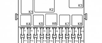
Interior fuse and relay box
The pre-storage unit in the Opel Astra J interior is located on the driver’s side (left) behind the glove compartment (glove compartment).
To access the fuse and relay box you must:
- Open the box and push its right wall to the left;
- Then remove the limiter on this wall from the hook with the edge of the socket in the instrument panel;
- All that remains is to fold the storage compartment down and remove its hinges from the grooves in the instrument panel.
Fuse diagram in the interior of the Opel Astra j
| No. on the diagram | Denomination pre-la | Protected circuit |
| 1 | 10 A | Display/Driver Information Screen (DIC), Radio Control |
| 2 | 20 A | Exterior lighting, body electronics control unit |
| 3 | 25 A | Body electronics control unit |
| 4 | 20 A | Radio (audio system, radio), |
| 5 | 7.5 A | Infotainment system, multimedia player, cell phone |
| 6 | 20 A | Cigarette lighter (front power outlet) |
| 7 | 20 A | Rear power socket for accessories |
| 8 | 30 A | Low beam (halogen) - Left headlight |
| 9 | 30 A | Low beam (halogen) - Right headlight |
| 10 | 30 A | Door locks (Central locking) |
| 11 | 40 A | Heating/heating (ventilation) and interior air conditioning systems (stove and air conditioner fan) |
| 12 | 25 A | Electric motor/driver's seat (adjustable position and lumbar support) |
| 13 | — | Empty (Reserved) |
| 14 | 7.5 A | Connector for Diagnostics (diagnostic plug) |
| 15 | 7.5 A | Airbags (SRS Airbag) |
| 16 | — | Empty (Reserved) |
| 17 | 10 A | Air conditioning (A/C); control panel for the ventilation, heating and air conditioning system |
| 18 | 30 A | Logistics mode No. 1 |
| 19 | 20 A | Stop lights, reversing lights, courtesy lights/lamp |
| 20 | 5 A | System for detecting the presence of passengers inside the cabin |
| 21 | 10 A | Dashboard |
| 22 | 5 A | Ignition; egnition lock |
| 23 | 20 A | Body electronics control unit |
| 24 | 20 A | Body electronics control unit |
| 25 | — | Empty (Reserved) |
| 26 | — | Empty (Reserved) |
The cigarette lighter fuse is number 6 (front) and 7 (rear) with a current rating of 20 amps.
New relay
A windshield wiper relay with an adjustable pause for VAZ-2107, IZH, Lada Granta and other car models must be selected correctly. There are several popular manufacturers of the presented equipment, whose products are in great demand today.
For domestic cars with a new safety block, as well as foreign cars with the same arrangement of structural elements, the most popular model is 723.3777-05. This relay is produced by Energomash CJSC. The cost of such a device is about 200 rubles.
It should be said that there are many cars driving on domestic roads whose safety unit has an old configuration. For such vehicles, the most popular models are 724.3777-01 and 39.3777-03. The first design is produced by ZAO Energomash, and the second is produced by the no less popular brand “Russian Partner”. The cost of such products is also in the range of 170-200 rubles.
A windshield wiper relay with an adjustable pause for VAZ-2110, IZH, Priora and other car models does not have to be new. On sale are control units that have already been installed in one or another brand of vehicle. There are quite a lot of high-quality relay models presented in this category.
The advantage of used types of control units is that they are completely ready for installation. Most often, such designs have undergone high-quality modifications. In this case, installing the relay in the seat will be much easier. The connection is made using prepared wires. The location for installing the relay will not need to be re-equipped.
Experts say that used designs are largely intended for domestic car brands. Owners of foreign cars are recommended to purchase new units. In this case, the modification of the design will be optimal for the corresponding brand of car.
Block in the trunk
In the luggage compartment, the fuse and relay box is located on the left side under the side wall trim.
To access you need:
- Turn the lock of the trim cover 90 degrees and fold it down.
Fuse and relay diagram in the luggage compartment of the Opel Astra j
| No. on the diagram | Denomination pre-la | Protected circuit |
| 1 | 40 A | Trailer control unit |
| 2 | 30 A | Towbar, towing device (trailer plug connector, trailer socket) |
| 3 | 5 A | Parktronic; Parking assistance system |
| 4 | — | Empty (Reserved) |
| 5 | — | Empty (Reserved) |
| 6 | — | Empty (Reserved) |
| 7 | 10 A | Electric motor/passenger seat drive (position and lumbar support adjustment) |
| 8 | 5 A | Alarm (anti-theft) |
| 9 | — | Empty (Reserved) |
| 10 | 5 A | Body electronics control unit |
| 11 | 5 A | Tire pressure sensor, trailer alarm (light) |
| 12 | — | Empty (Reserved) |
| 13 | 20 A | Towbar, towing device (trailer plug connector, trailer socket) |
| 14 | — | Empty (Reserved) |
| 15 | 7.5 A | Side Rear View Mirror Switch, Driver Power Window Switch |
| 16 | 5 A | Dimmable interior rearview mirror |
| 17 | 20 A | 12 V socket in the trunk (station wagon) |
| 18 | — | Empty (Reserved) |
| 19 | 10 A | Heated steering wheel (heated steering wheel) |
| 20 | 20 A | Sunroof |
| 21 | 25 A | Heated/heated seats |
| 22 | — | Empty (Reserved) |
| 23 | — | Empty (Reserved) |
| 24 | — | Empty (Reserved) |
| 25 | — | Empty (Reserved) |
| 26 | — | Empty (Reserved) |
| 27 | — | Empty (Reserved) |
| 28 | — | Empty (Reserved) |
| 29 | — | Empty (Reserved) |
| 30 | — | Empty (Reserved) |
| 31 | 30 A | Audio system (radio) amplifier |
| 32 | 10 A | Active Suspension Damping System, Lane Departure Warning System |
Relay in trunk
| No. on the diagram | Protected circuit |
| R1 | Ignition relay 0 |
| R2 | Ignition relay 1 |
| R3 | Door lock relay |
| R4 | Empty (Reserved) |
Features of relay replacement
Before making a replacement, you need to consider the technology for carrying out this work. It is advisable to study the manufacturer's instructions. It indicates how the wiper control system works.
In some models this procedure is simpler. Many foreign-made cars have a system modification feature. The fact is that vehicles are supplied to the market with both full and cheaper equipment. In the second option, the manufacturer initially assumes that the driver can carry out modifications if desired.
If an additional control unit is installed on a similar foreign car and a domestic car, the procedure will be different. The windshield wiper relay with an adjustable pause for Grant, Priora, and VAZ is somewhat more difficult to install. However, when purchasing a modified used part, this procedure is greatly simplified.
Block under the hood
In the engine compartment, the fuse box is located next to the battery.
To access you need:
Use a screwdriver (or your fingers) to press out the two latches and remove the protective cover.
Fuse and relay diagram under the hood of the Opel Astra j
| No. on the diagram | Denomination pre-la | Protected circuit |
| 1 | 10 A (gasoline) and 20 A (diesel) | (ECU) engine control module (ECM) |
| 2 | 10 A | Oxygen concentration sensor |
| 3 | 15 A | Fuel injection, ignition system (4 fuel injectors, ignition coil) |
| 4 | — | Empty (Reserved) |
| 5 | — | Empty (Reserved) |
| 6 | 7.5 A | Heated/heated mirrors (side mirrors left and right) |
| 7 | 5 A | Radiator Fan Control (Medium Speed Relay), Electric Fan Motor |
| 8 | 7.5 A | Oxygen concentration sensor |
| 9 | 7.5 A | Sensor / Rear Window Sensor, Body Control Module |
| 10 | 5 A | Battery sensor |
| 11 | 7.5 A | Trunk/tailgate release button |
| 12 | 5 A | Front adaptive lighting control module (interior lamps) |
| 13 | — | Empty (Reserved) |
| 14 | 20 A | Rear windshield wiper (rear wiper motor) |
| 15 | 10 A | (ECU) engine control module (ECM) |
| 16 | 30 A | Starter |
| 17 | 10 A | Transmission control system (TCM) |
| 18 | 40 A | Heated / heated rear window (heating filaments) |
| 19 | 30 A | Driver and passenger front power windows |
| 20 | 30 A | Rear passenger power windows (right and left) |
| 21 | 30 A | ABS brake system |
| 22 | 10 A | High beam - Left headlight |
| 23 | 25 A | Headlight washers (pump) |
| 24 | 15 A | Low beam (xenon) - Right headlight |
| 25 | 15 A | Low beam (xenon) - Left headlight |
| 26 | 15 A | Front left and right fog lights (fog lights) |
| 27 | 30 A | Electric diesel fuel heater |
| 28 | — | Empty (Reserved) |
| 29 | 30 A | Electric parking brake (Handbrake) |
| 30 | 60 A | ABS brake system |
| 31 | — | Empty (Reserved) |
| 32 | 5 A | Airbags (SRS Airbag) |
| 33 | 15 A | Headlight leveling control system (AFL) see also No. 50 |
| 34 | — | Empty (Reserved) |
| 35 | 5 A | Driver's side power window switch, side mirror control switch |
| 36 | — | Empty (Reserved) |
| 37 | Canister purge solenoid valve | |
| 38 | 20 A | Vacuum pump (gasoline) |
| 39 | 20 A | Fuel pump flow regulator module (fuel pressure regulator) (gasoline) |
| 40 | 10 A | Windshield (front) glass washers, rear window washer; washer motor |
| 41 | 10 A | High beam - Right headlight |
| 42 | 40 A | Engine cooling radiator fan |
| 43 | 30 A | Front windshield wiper (front wiper motor) |
| 44 | — | Empty (Reserved) |
| 45 | 30 A | Engine cooling radiator fan (petrol engine) |
| 46 | — | Empty (Reserved) |
| 47 | 15 A | Signal (horn, horn) |
| 48 | 60 A | Cooling fan 1 medium speed, cooling fan low (small) speed, cooling fan high (increased) speed |
| 49 | 20 A | Gasoline pump (fuel pump) |
| 50 | 10 A | Headlight adjustment system (headlight corrector); adjusting the angle of the right and left headlights |
| 51 | Throttle module | |
| 52 | 7.5 A | Heating of crankcase gases |
| 53 | 7.5 A | Transmission control system (automatic transmission), (ECU), engine control unit (ECM), glow plug control unit (GPCM) (for diesel cars) |
| 54 | 7.5 A | Electrical wiring control; Brake Power Vacuum Switch, Fuel Pump Control System, Water in Fuel Sensor, Auxiliary Electric Heater, K33 HVAC Control Module, P16 Instrument Cluster, B108 Air Quality Sensor, B19C Brake Power Vacuum Switch, B75B Mass Flow Sensor air/intake air temperature |
| Z1 | 80 A | Diesel models: glow plug control unit |
| Z2 | 80 A | Steering system control unit with servo amplifier |
| Z3 | 100 A | Additional (auxiliary) electric heater |
| Z4 | 80 A | Electric cooling fan motor |
The washer fuse is number 40 with a current of 10 Amps.
Relay in the block under the hood
| No. on the diagram | Protected circuit |
| R1 | Empty (Reserved) |
| R2 | Starter relay |
| R3 | Engine Control (EC) Relay, Transmission |
| R4 | Rear window heating/defogger relay |
| R5 | Headlight washer pump relay |
| R6 | Low Beam Headlight Relay - Left Headlight, Daytime Running Light (Dimensions) |
| R7 | Fuel pump relay |
| R8 | Low Beam Headlight Relay - Right Headlight, Daytime Running Light (Dimensions) |
| R9 | Fuel heater relay (diesel) |
| R10 | Empty (Reserved) |
| R11 | Cooling fan 1st (low, low) speed relay |
| R12 | Cooling Fan Overspeed Relay |
| R13 | Cooling Fan Medium Speed Relay 1 |
| R14 | Main ignition relay |
There are also maintenance-free relays inside the mounting block. To get to them, you need to remove the fuse mounting block and disassemble its plastic protective casing to remove the main board with relays and fuses.
Maintenance-free relays on the back of the board with fuses and relays under the hood
| No. on the diagram | Protected circuit |
| Maintenance-free relays located inside the unit | |
| R1 | Signal Relay (horn, horn) |
| R2 | Rear window washer pump relay |
| R3 | Rear window wiper relay |
| R4 | Front windshield washer pump relay |
| R5 | Air Conditioning Relay (A/C), A/C Compressor Clutch |
| R6 | Fog lamp relay (front fog lights) |
| R7 | High beam relay |
| R8 | Fuel filler door opening motor relay |
| R9 | Rear tailgate lock opening relay (including trunk lid) |
For information: The generator voltage regulator relay is installed in the engine compartment next to the generator itself; it is not in the main fuse and relay box.
Beginning of work
To install a windshield wiper relay with an adjustable pause with your own hands, you must first dismantle the wipers. Their design may vary significantly depending on the vehicle model. It is also worth noting that the brushes can be front or rear. However, regardless of their type, the relay is located on the vehicle glass.
If there is no wiring diagram for the wipers, you can find the installation location of the control unit yourself. To do this, you need to inspect the base of the brushes. Most often, in foreign and domestic cars, this element is screwed to the car body.
Most often, the relay is located near the hood release handle. When the part is found, it is dismantled. To do this you need to prepare a simple screwdriver. The old relay is removed very carefully. You must try not to scratch the body or damage other elements of the system. You also need to remove the wiper column.
Rear window wipers
Malfunctions in the operation of rear window wipers are usually associated with the steering column switch, gear motor, power wires, broken drive teeth, and worn brushes. The relay does not affect the operation of the rear wipers, so its malfunction can be ruled out. The methods for eliminating other breakdowns are the same as for the front wipers.
Repair of windshield wipers mainly comes down to replacing damaged components, cleaning electric motor parts, cleaning and lubricating moving joints, and straightening deformed levers. Repair costs are low, and using contract spare parts from JapZap will keep them to a minimum. The procedure for dismantling and installing different components of this assembly may differ in different cars, but the general principles for troubleshooting are the same.
Installation process
The windshield wiper relay with adjustable pause is easy to install yourself. To do this, you need to find the brush block and open the cover on it. There used to be an old relay here. Ideally, the new control unit has been modified and can be easily installed in an existing mounting location.
After this, you need to configure the system. After installing all elements of the system in the reverse order, it is necessary to turn on the intermittent wiper movement mode. In this case, the pause will last the standard amount of time. Next, you can set your settings.
To do this, the driver must turn off the brushes. After this, it maintains the required time interval. For example, it will be 2 seconds. Then the driver switches on the intermittent brush movement mode again. In this case, the relay will remember how often you need to sweep the wipers. This is a very convenient way to control the movement of the brushes.
Features of the improvement
You don’t have to buy a windshield wiper relay with an adjustable pause, but simply modify it. This is a rather complicated process. It requires appropriate preparation from the master. You will need to have at least a basic level of soldering techniques and knowledge of electronics. It is for this reason that it is easier to buy a new device.
However, if you wish, you can carry out the modification yourself. To do this, you need to remove the cover and remove the board. The interval between strokes is controlled by a resistor. It is quite easy to find for a person who understands electronics. To create a pause of 4 seconds, the relay includes a 62 KOhm resistor. If you decrease this value, you can reduce the interval between strokes.
Wiper relay rs 514
This article is located at: https://www.semerka.info/node/164. I agreed with the author on copying the article to the NIVA-FAQ website and sent it to Sergey_SS.
The standard VAZ windshield wiper works great in heavy rain, but in light drizzling rain, unfortunately, its performance cannot be called good, I’m talking about those moments when it works intermittently. The standard pause between wiper sweeps is 4 seconds. Very often, when the rain is very light, the glass does not have time to get wet, and the wipers practically work dry. The driver, cursing AvtoVAZ employees in native Russian expressions, will need to turn the windshield wiper on and off himself every 5-10-20 seconds. In general, I think any VAZ owner understands what I want to say. And today we will fight this problem. So, we remove the windshield wiper relay from the car, disconnect the block and take it home:
Open the lid and disconnect the printed circuit board from the lid. Let's look at the diagram. The resistor circled in red is responsible for the pause between sweeps of the wiper:
By changing its resistance, you can and even need to adjust the pause between sweeps of the wipers. The resistor itself is 62 Kohm, which equals 4 seconds between strokes. If you are satisfied with a minimum delay time of 4 seconds, then you can leave this resistor. I had a 47 kOhm resistor, and I installed it so that the minimum delay time was 3 seconds. If you set it to 25-30 kOhm, the delay time will be about 2 seconds. So, if you decide to leave the original resistor, then solder any one of its legs from the board; if you change the resistor to a lower value, then solder the original resistor, and solder the new one with only one leg. We take half a meter of two-core wire (or two single-core wires) and solder one wire to the free leg of the resistor. And the second wire goes to the place where the freed leg was removed. Like this:
The wires in the photo are wearing a transparent heat-shrinkable casing - a very convenient and effective method of insulation. We simply put the tube over the connection and heat it slightly with a lighter, the tube shrinks in diameter and settles tightly on the connection, this is much more effective than electrical tape.
So now we have two wires soldered, we make a knot on them so as not to accidentally tear them off, and close the lid, pulling our wires along with the standard ones. Glue the relay cover. I personally glued with a hot glue gun:
Next we take a variable resistor:
The resistor value can be any from 100 kOhm. The higher the denomination, the longer you can pause between brush strokes. For example, if the resistor is 100 kOhm, then the maximum interval between brush strokes will be about 10 seconds. If you take 200 kOhm, the interval will be about 17 seconds and so on. The only thing is that I don’t recommend taking more than 500 kOhm, because the accuracy of setting the interval will decrease. So, we take a resistor and solder one wire (any) to the middle contact, and the second to any extreme one.
The whole device is ready:
We take everything back to the car. We put the relay in its rightful place, and place the resistor where it is more convenient for you. I personally placed it on the steering column next to the windshield wiper switch. IMHO this is more logical and correct. And he put on it the knob from the stove regulator from the figure eight:
That's it. Everything is ready. Now in intermittent mode, the time between wiper strokes is adjustable from 3 to 10 seconds, the resistors are 47 kOhm (0.25 W) and variable 100 kOhm 0.25 W. In terms of watts, you can take any resistors (but 0.25 is a convenient size for us). In the future, I’m thinking of changing the resistors to 30 kOhm - to make the minimum pause time 2 seconds and variable to 200 kOhm or 500 kOhm, to make the maximum pause time longer, up to 17-18 seconds with a 200 kOhm resistor or almost up to a minute with a resistor at 500 kOhm Everything described in the article was modified using the PC-514 wiper relay - this is what is installed on most cars, but if you have another relay, then I think that it can be modified in the same way.
Thoughts about the “regulated pause” have been tormenting me for a long time, but the “sudden arrival” of spring “nudged me”, and I went to the Internet for a ready-made solution to this issue. Of the many different options, the above material was recognized as one of the best in terms of speed, ease of execution and budget. The picture was slightly overshadowed by the fact that my “native” relay turned out to be an “old” model - also with a thermocouple, which slightly increased the budget of the event, but, on the other hand, for the period of experiments I did not have to give up the usual wiper mode.
A new RS-514 relay was purchased at a nearby store, but it also turned out to be not the same relay as described above (as it turned out, there are several modifications that are not designated in any way.), although on the same microcircuit. After sitting for a while on the new relay board, I found an analogue of the “resistor circled in red.” This is R2 with a nominal value of 33 kOhm:
Resistor R2 was mercilessly discarded due to inconvenience of use. For me, given the lack of a soldering iron with a power of less than 100 W, it was more convenient to solder a constant resistor to the lower “contact” of VD2 (left contact R2 in the photo), and the wire to the “+” of the capacitor (one track with the right contact R2). With a constant resistor of 30 kOhm and a variable resistor of 200 kOhm, the minimum pause was about 4.5 seconds, the maximum - 32 seconds.
The total budget for “rework” (as of March 2011): imported resistor, with inertial lubrication and with a handle - 35 rubles, new relay - 100 rubles, permanent resistor - 2 rubles, wire, piece of heat-shrinkable tube, soldering iron and, of course, hands.
Revision procedure
The old resistor needs to be removed from one side. One wire is soldered to its free leg. The second core must be connected to the place where it was installed. The wire can be used one two-core or two single-core. The second end is connected to the central contact.
Next, the relay cover can be closed and the device installed in the system. Its functionality is checked.
Having looked at how to select and install a variable pause wiper relay, you can perform this procedure yourself.