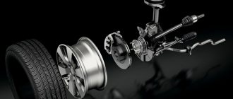
One of the main systems that ensures safety when driving a car is the braking system. The most widespread are brake mechanisms that use the frictional force of different materials. Such mechanisms are installed on all cars, including VAZs belonging to the “Classic” family.
As an example of a classic VAZ, model 2107 will be used. The brake system of the VAZ-2107 includes working and parking systems. The task of the working component is to reduce the speed of movement of the car until it is completely immobilized.
It consists of two components: the first is the brake mechanisms, which act on the wheels, which is why their rotation decreases. The second component is the drive, through which the driver operates the mechanisms.
The parking component ensures that the wheels of one of the car's axles are locked, in the case of the VAZ-2107 - the rear axles, while the car is immobilized. The use of this brake prevents spontaneous movement of the car. This system uses a separate drive that acts on the rear axle mechanisms.
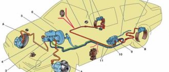
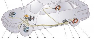
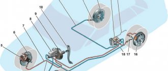
In more detail, what the brake system of the VAZ-2107 looks like is shown in the diagram:
Now let's take a closer look at the design of the VAZ-2107 brake system. First, let's go through the working component. Its drive is hydraulic and includes:
- Control pedal;
- Vacuum booster;
- Main cylinder;
- Tank for working fluid;
- High pressure pipelines;
- Rear axle bellows pressure regulator;
The use of liquid as a working element of the drive is due to a number of positive qualities: a complex system of levers for the drive is not required, the wiring of pipelines to the mechanisms is facilitated, the transmission of force from the driver’s foot is enhanced several times due to the vacuum booster.
Related link:
Description and installation of the “Lunfey” heater on a VAZ
The working mechanisms on the VAZ-2107 are of two types: disc brakes are installed at the front, using calipers; drum-type mechanisms are used on the rear axle, which also includes a parking mechanism.
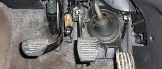
Now in more detail about the elements of this system. So, the pedal that the driver presses is located on the same axis as the clutch control pedal. To ensure that it can be returned to its original position, it is spring-loaded.
Vacuum brake booster
A rod connected to the amplifier is connected to the pedal. The design of the VAZ-2107 vacuum brake booster is quite interesting; it is shown in the figure:
The amplifier is a sealed container, internally divided into 2 chambers by means of a membrane. The chamber located closer to the pedal is called atmospheric, and the chamber separated from it by a membrane is called vacuum. The diaphragm itself is connected to the piston rod of the master cylinder.
The vacuum chamber is connected by a pipe to the intake manifold of the engine, where the vacuum comes from. The design also includes a follower valve controlled by the pedal rod, which does all the work.
When the pedal is released, this valve connects the chamber cavities through a channel, providing identical pressure. When the pedal is applied, the valve closes the channel connecting the chambers and opens the channel connecting the atmospheric chamber with the atmosphere. Since a vacuum is maintained in the second chamber, atmospheric pressure begins to put pressure on the membrane. Since it is connected to the piston rod of the master cylinder, due to the movement of the piston, fluid is displaced from the cylinder into the pipelines.
Brake master cylinder
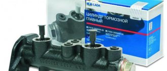
The master cylinder is connected to the booster. This element is a housing to which the supply and return pipelines from the fluid reservoir are connected, and 3 pipelines leading to the brake mechanisms exit. There is one pipeline leading to the front brake mechanisms, and only one to the rear, leading to the regulator.
Inside this housing there are pistons that push the liquid into the pipelines. One of them is connected to the amplifier diaphragm rod. These are the main elements of the drive. The detailed design of the brake master cylinder is shown above.
Related link:
Causes of detonation of VAZ engines and solutions
Replacing front pads (using the example of Lada Granta):
- To release the pads, the lock washer must be released.
- Next, unscrew the bracket bolt.
- The bracket body is rotated on the axis of the upper bolt.
- Retracting the pistons of the mechanism, remove the pads.
The difference between the classic VAZ models is the use of fastening pins in the front disc mechanism, which are pinned. When replacing brake pads, if pad wear indicator wires are installed, they must be disconnected, but before doing this, turn off the power supply to the car.
Before installation, you should inspect the surface of the pistons, boots, bolts or studs, and, if necessary, remove rust and treat with brake fluid. Pay attention to the presence of brake fluid leaks. It is also mandatory to monitor the condition of the brake disc surface for the formation of grooves and uneven wear. If necessary, the disc is polished.
Assembly is carried out in reverse order. In this case, the pistons of the brake cylinder are recessed inside. To do this, you will need to press lightly on it, but the brake fluid should not leak out of the neck of the expansion tank.
Caliper device
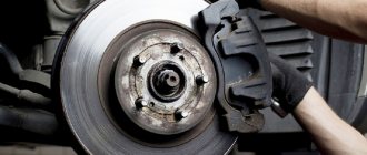
Let's move on. The front axle mechanisms are disk ones, consisting of calipers with the main brake elements - pads, and brake discs.
A caliper is a body with cylinders made in it for the pistons. This model has two of them, one for each block. The support structure is shown in the figure.
The caliper pistons have the form of a glass, which is placed in their cylinders, but they can move along it. To prevent fluid leakage, the pistons are equipped with o-rings.
Pads are small metal plates onto which linings made of friction material are glued.
The brake disc is made of metal for better adhesion to the surface of the pads; its side surfaces are well processed so that there are no protrusions or shells on them.
The VAZ 2107 brakes work like this: the fluid moves into the caliper cylinders, where it begins to push out the pistons. They come out of the cylinders, pressing the pads against the disc.
Replacing the main (main) brake cylinder:
The need for such replacement occurs much less frequently. Basically, the reason for such interference is the appearance of brake fluid leaks, or the passage of fluid between different cavities through the sealing cuffs.
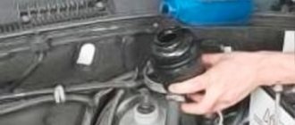
To remove the barrel, you will need to disconnect the battery and the electrical connector of the tank cap. Then remove the cap and pump out the brake fluid completely. The tank is attached to plastic clips and can be easily replaced.
Work on this brake cylinder (or installation after repair) is carried out after disconnecting the high pressure pipes. The main brake cylinder is attached to the body with two bolts. After reinstalling the cylinder, the brake system must be bled.
Rear axle brake mechanism
The brake system of the VAZ-2107 rear axle has a different device. All its elements are hidden inside the brake drum:
The working brake cylinder of the VAZ 2107 has the following device: there is a body, also known as a cylinder, with two pistons placed in it. When exposed to fluid pressure, they come out of the cylinder.
The pads are metal, made in the shape of crescents, with friction clutches glued to their upper edge. The pads installed on the hub form a ring.
In the lower part, the pads are installed in the seats made under them, and in the upper part - in the grooves made in the pistons. To prevent the pads from moving apart spontaneously, they are tightened with springs. The parking brake mechanism is also located there.
On top of all this there is a drum mounted on the hub shaft. When braking, the fluid pushes the pistons, and since the pads fit into their grooves, this movement of the pistons is accompanied by the divergence of the pads. At the same time, they are pressed towards the drum and the rotation slows down.
Related link:
Insulation of VAZ-2107 for the winter
Rear brake cylinder replacement:
To replace the brake cylinder on the rear wheel, you will need to carry out similar operations to remove the brake pads described earlier. Next, the following operations are carried out:
- Unscrew the brake pipe nut. You will need to thoroughly clean the mounting area and use an open-end wrench with the ability to grasp all edges of the nut.
- There are also two bolts (may differ on old and new models) for securing the cylinder, which will also need to be removed.
- The new cylinder assembly is installed in the reverse order.
Parking system
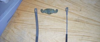
Although it engages the mechanism of the rear axle wheels, it is in no way connected with the working mechanism. It uses a cable as a drive connected to the handbrake located inside the car.
Under the car, this cable is divided into two parts, going into the rear axle mechanisms. Inside, the ends of the cable are connected to the drive lever, which in turn is connected to a spacer bar. The drive lever is connected to one of the pads.
When the handbrake is engaged, the cable pulls the lever, and since it rests against the bar, the pads are released. The toothed sector of the handbrake fixes the position of the lever when the pads are spread apart.
Connection circuits
Brake failure has always been every driver's biggest nightmare. Therefore, engineers have long figured out how to make it possible to stop a car even with a damaged brake system (and it is easier to damage a hydraulic system than any other. A seal leaks - and hello hot).
One of the options for insurance in case of failure was to split the system into two circuits. It turned out that dual-circuit brakes are not as complicated as they could be, but they are reliable and safe. Even if one of the circuits fails, the system will continue to operate, allowing an accident to be avoided.
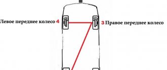
There are 5 options for layout of hydraulic system circuits:
- 4+2, parallel with front axle belay. One circuit powers all four wheels, the second only the two front ones.
Parallel circuits, 4+2 scheme - 2+2, parallel. One circuit for the front axle, the second for the rear. This is how rear-wheel drive cars are most often designed.
Parallel circuits, 2+2 scheme - 2+2, diagonal. One circuit goes to the left front and right rear wheels, the second to the right front and left rear. This system is usually installed on front-wheel drive cars.
Diagonal contours, 2+2 scheme - 3+3, combined. One circuit goes to the front wheels and the right rear, and the other also goes to the front wheels and the left rear.
Combined circuit, 3+3 circuit - 4+4, parallel. Two circuits are supplied to all 4 wheels in parallel.
Parallel circuit, 4+4 circuit
In most cases, the car owner does not even think about what kind of circuit separation scheme he has. The brakes work - and great.
Pressure regulator
It is installed in the rear wheel drive and not only distributes fluid to the mechanisms, it also prevents possible skidding due to different forces on the mechanisms. This is done by limiting the supply of pressure to the mechanisms, depending on the position of the car body relative to the bridge.
The regulator is driven by a rod, one end of which is fixed to the rear axle, while it itself is fixed to the body. As the load on the rear axle increases, the body changes position relative to the axle; as a result, the rod puts pressure on the regulator piston, which adjusts the pressure supplied to the mechanisms.
How a sorcerer works and works
This is a small device that helps distribute the force correctly when braking. Between which elements does it distribute force? And everything is simple - between the front and rear wheels.
You may ask - why is this necessary? If there were no sorcerer, then the braking force would be applied equally to all wheels. But they are loaded differently during movement. The less grip a wheel has on the road, the lower the braking force on that wheel should be. This is what the so-called “sorcerer” does. That is, the lower the rear of the car is lowered, the greater the braking force. The more it rises, the less effective the brakes on the rear are.
In the picture you can see where this important element is located.
- Brake pressure regulator (sorcerer).
- Elastic lever of the sorcerer.
- Rear suspension beam.
The principle of operation of the VAZ-2107 brake system
If it is necessary to reduce speed, the driver presses the pedal. Its force is transmitted to the amplifier valve, which opens the required channel to supply atmospheric pressure to the membrane. The membrane is connected to a rod connected to the piston of the main cylinder. This rod displaces fluid into the pipelines leading to the operating mechanisms. Since the liquid is not compressed, all force is completely transferred to the mechanisms.
The liquid presses on the pistons of the working cylinders, and as they move out, they unclench (on drum bellows) or press the pads (on disk bellows) to the disk or drum connected to the wheel hubs. Due to the friction of the pads on the discs (drums), the rotation slows down.
Related link:
Installation of radio VAZ 2107
Rules for operating vehicles in the nine
When operating the “nine”, it is necessary to strictly observe the scheduled maintenance periods not only for the engine, but also for the vehicle, and also to carry out repairs of the master brake cylinder (MBC) of the VAZ 2109. This applies to the friction linings of the front disc and rear drum brakes. Complete wear of the friction linings threatens unexpected vehicle failure in an extreme situation.
Periodically it is necessary to check the condition of the linings, monitor their level of wear and replace if necessary. It is necessary to carefully monitor the brakes of the VAZ 2109 in terms of fluid leakage through worn gaskets and seals.
Excessive wear of sealing elements is accompanied by:
- the risk of insufficient effort in the shopping center;
- pedal failure when driving;
- increasing braking distance.
All of the above creates very serious risks. A vehicle is one of the critical systems for ensuring the safety of the driver, passengers and other road users.
Types of maintenance work
Despite the fact that the system is not so complicated structurally, it requires periodic maintenance, including:
- Checking the fluid level in the system;
- Checking the degree of wear of friction clutches, pads, discs, drums;
- Bleeding the system to remove air;
- Checking the condition of the handbrake cables;
- Adjustment of cable tension;
- Adjusting the rear brake adjuster;
Before each trip, you must always check how much brake fluid is in the VAZ-2107 system. An insufficient amount of it can lead to the fact that the efficiency of the system can be significantly reduced due to air getting inside the pipelines. In addition, a decrease in level may indicate damage to pipelines and fluid leakage.
The elements of the mechanism should be checked every few months, this is especially true for the pads, since they wear out quite intensively. If necessary, worn elements are replaced.
If air gets inside the drive of the working system, pumping is performed, as a result of which the air is expelled from the system.
Loosening the tension of the parking brake cables can lead to its failure, so you need to periodically monitor it and, if necessary, restore the tension.
Replacing the parking brake cable:
In most cases, the tension of the handbrake cable is adjusted by its tension at the point of attachment to the equalizer. However, if adjustment cannot be made, replacement will be required:
- Remove the brake drum.
- Remove the muffler from the hanging clips and lower it to the ground.
- Dismantle the equalization device.
- Remove the cable end from the equalizer.
- Release the cable attachment to the body elements.
- Remove the opposite end of the cable from the brake mechanism by disconnecting it from the drive lever. Pull the cable out of the stationary shield.
- Carry out reverse laying, fixing and tensioning of the cable.
Features of the braking system
One of the features of the VAZ-2107 brake circuit is the presence of a dual-circuit system. The essence of a dual-circuit system is that the working drive is divided into two parts, each of which supplies fluid to only two mechanisms, while the circuits do not interact with each other.
The presence of two circuits ensures the operability of the brakes of at least two wheels in the event of depressurization of one of the circuits. That is, even if the pipelines of one circuit are punctured, the second will remain fully operational, which will ensure the functioning of the brakes.
In the VAZ-2107, the circuits are divided in such a way that the drive of the front axle mechanisms is separated from the drive of the rear mechanisms. This allows you not only to maintain the functionality of the system when one of the circuits fails, but also to pump each circuit separately. That is, if one of the circuits is airy, then it needs to be pumped, but it is not necessary to service the second one.
Related link:
The main reasons for the lack of battery charging on the VAZ 2107
This is only general information about how the VAZ-2107 brake system works, and does not include all the details on its maintenance and repair. In general, the brakes of this car work quite well, although some elements of it cause complaints from car owners.
Article on the topic - Bleeding VAZ brakes
Design of a domestic braking system
The brake system on the VAZ 2110 has a main element - a dual-circuit regulator with a mandatory vacuum booster. The regulator is responsible for the pressure in the brakes on the rear axle, and to be more precise, it creates this pressure.
Mandatory brake hoses and basic elements equip the brake drive and divide it into two complete circuits. Thanks to this, braking occurs in both the front and rear wheels, which is optimal and safe.
In general, there is nothing unusual in the technical component.
The location of the brake pedal in the VAZ 2110 is classic - in the middle, like most cars with a manual transmission. It is this pedal that activates the braking system. Some may call it a priori heavy or tight, but most drivers are happy with everything and with any changes in the squeeze they begin to think about whether the brake system on the VAZ 2110 is in danger of being repaired.
System hydraulic drive elements
- Pressure regulator drive, which transports brake fluid to the rear brake mechanism. The presence of brake fluid is mandatory, as in all cars.
- Main (main) cylinder with pistons and reservoir. It is equipped with a fairly accurate sensor that shows the brake fluid level. You need to pay attention to it, mainly to prevent an emergency level, which can lead not only to a breakdown of the entire system, but also to an accident.
- A vacuum booster that creates pressure that is directed into the master cylinder piston. Which is what creates the inhibition. Problems with the vacuum booster can cause quite a lot of trouble.
- Pressure regulator in the brake system, responsible for the pressure force. It can reduce and increase the indicator, focusing on the load of the rear axle of the “tens”. And in a correct, not broken condition, the loads on the axles should be the same, but without a pressure regulator, using the brake system will be difficult.
- The rear wheel mechanism, in which the brake system is drum by default from the factory, the 2110 does not have modifications with rear disc brakes. There is an opinion that drums are not very reliable, so some owners change the rear brakes to disc ones.
- The front wheel mechanism consists of pads, disc and cylinders. The “Ten” is equipped with a front brake wear sensor. The front brakes can be either ventilated or not.
The role of the pressure regulator in the brake system
People call the regulator quite original - the sorcerer. But all VAZ 2110 owners know or consider it necessary to change the pressure regulator and monitor its technical condition.
Diagram of the brake pressure regulator VAZ 2110: 1 - pressure regulator housing; 2 - piston; 3-protective cap; 4.8- retaining rings; 5 — piston sleeve; 6 — piston spring; 7 — body bushing; 9, 22 — support washers; 10 — sealing rings of the pusher; 11 — support plate; 12 — pusher bushing spring; 13 - sealing ring of the valve seat; 14 — valve seat; 15 - sealing gasket; 16 - plug; 17 - valve spring; 18 - valve; 19 — pusher bushing; 20 — pusher; 21 - piston head seal; 23 - piston rod seal; 24 - plug; A, D - chambers connected to the main cylinder; B, C - chambers connected to the wheel cylinders of the rear brakes; K, M, N - gaps.
