VAZ cars are very popular among drivers due to their decent technical characteristics, price-quality ratio, and excellent maintainability. Most malfunctions that occur during operation can be corrected by the driver independently without the help of professionals.
In this article we will talk about repairing a vehicle heater, which is one of the weak points in domestically produced cars, namely, we will look at how to replace a failed VAZ-2110 heater resistor.
How to replace an additional heater motor resistor?
- We find an additional resistor and remove the contacts from it.
- Unscrew the fastening of the additional resistor.
- We take out the additional resistor.
- We make repairs when possible.
- Install in reverse order.
Resistor of the heating system VAZ 2110
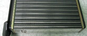
In a VAZ 2110 car, the heating system ensures the desired temperature in the cabin. The resistor is designed to select the mode in which the fan will operate.
Tips for using the stove
For several years of production of cars of the “tenth” VAZ family, engineers did not provide for the possibility of modifying the rheostat. The design with this part does not allow you to be 100% confident in the reliability of the heater. It is also worth noting that the location of the part is not the most convenient.
To ensure long-term operation of the resistor, we recommend following the following recommendations:
- use the stove in different positions and do not allow long periods of operation in one mode;
- If there are extraneous noises, creaks and whistles from the fan, it is recommended to stop its operation until the cause of the noise is eliminated.
Because The price of this part is low, and it often breaks down - we recommend carrying a spare with you in case of breakdown. We also note that in the absence of a spare part, the operation of the faulty heating element can be restored by resoldering the contacts. This method is temporary, so having instructions for replacement will not be superfluous.
Otherwise, the design of the heater in the “tenth” VAZ family is simple, so it rarely fails. The weak link in this design is the rheostat, but understanding how to replace it allows you not to think about a possible breakdown.
Source
Features of the VAZ 2110 heating system
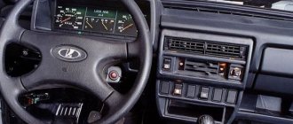
The heating system unit is controlled by two handles. So:
- The left one sets the desired temperature in the range from 16 to 28 degrees. The extreme positions of the handle, indicated by red and blue dots, ensure full opening or closing of the heater damper, supply of hot or cold air.
- The right handle sets the fan operating mode. When set to position 0 – the fan turns on, position I – the fan has a medium fan speed, II – low frequency, A – the fan is controlled automatically.
- Output controllers receive information from:
- a sensor that controls the air temperature inside the cabin;
- sensor that regulates the position of the micro-reducer shaft of the heating system damper drive - provides information about the position of the damper.
- In position A, the fan operating mode switch, the controller also controls the fan rotation speed, which depends on the difference between the available air temperatures of the controller and in the cabin.
- The recirculation valve, when the switch is turned on, accelerates the heating of the air in the cabin of the VAZ 2110 car. This occurs by blocking the flow of outside air into the cabin, and it circulates through the heater only in the cabin.
- The electric motor in the heater fan is excited by permanent magnets.
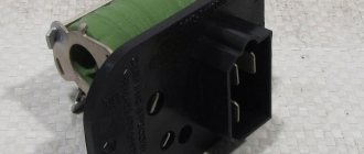
- A built-in additional resistor is used to create a low rotation speed. The device has two spirals: the resistance of one is 0.23 Ohm, the other is 0.82 Ohm.
- If both spirals are included in the circuit, this provides the first fan rotation speed.
- The 0.23 Ohm coil provides second speed.
- Disabling the resistor ensures the fan rotates at the maximum third speed, the value of which is 4100 rpm.
Tip: If a VAZ 2110 car has a faulty electric heater motor, it is better to replace it with a new one. Repair can only be carried out by cleaning the collector.
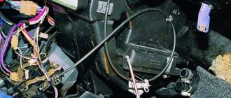
Replacing a resistor in the heating system of a VAZ 2110
If the fan in the heating system only works at the third speed, but does not switch to the first and second, the reason is most likely the failure of the resistor, which needs replacement. The VAZ heater resistor is shown in the photo.
Replacing a faulty resistance block
Because Apart from the body design, there are no differences in the mechanisms and main units between the VAZ 2110, 2111 and 2112; the instructions for replacing the heater rheostat are universal. You can repair a problem with the operation of the stove yourself if you have a couple of screwdrivers and several spanners.
The step-by-step process for replacing the rheostat looks like this:
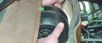
- Open the hood and unscrew the wipers.
- Next, remove the plastic trim under the windshield (“jabot”).
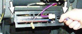
- Remove the chip with wires from the rheostat and remove it from its seat.
Important! Before starting work, you should make sure that the cause of the problem lies in the resistor. The test is easy: get to the part and connect the multimeter to the power wires, then turn on the ignition. Another sign of a problem is that the stove operates only in the 4th position.
Also, as a recommendation, we note that at the time of disassembling the plastic lining, you can clean the stove cavity. When driving in the autumn, dry leaves and dirt often get into the stove, which makes it difficult for the fan to rotate.
Replacing the heater resistor VAZ 2112 16 valves
I welcome everyone who loves to make, fix and repair everything with their own hands. Mr.PykoJob will help you with advice, show you with an example, disassemble and assemble everything simply and easily!
With the onset of cold weather, a malfunction of the VAZ 2112 heater appeared. The airflow only worked at maximum speed. It immediately became obvious that the problem was in the resistor of the electric heater fan.
The problem is unpleasant, but easy to fix. In this article I will show you how to deal with it and fix it if you encounter the same problem.
To get the resistor, you need to remove the frill, disconnect the terminal and, by unscrewing one screw, remove the resistor itself.
Since I have an old-style resistor, the difficulty was that the spring-loaded contact was unsoldered. Therefore, we solder it back and check the operation.
After a successful test, we install everything in place.
While installing the resistor, the screw fell off because... it is located in an inconvenient place. For those RukoJobs like me, I came up with a little life hack to get the screw and not lose it again:
I attached a neodymium magnet to a screwdriver - in this way I took out the screw and simply and conveniently screwed it into place.
Source
Let's sum it up
One of the important elements that affects the functionality of a car heater is a resistor. It performs the important function of distributing current from the battery to the electric elements of the heater. If a problem with the operation of the current converter is detected, the product must be replaced.
Do not ignore the malfunction of parts that relate to current - this may be unsafe for your life. Immediately after identifying a problem, eliminate its cause.
Types of rheostats
A popular type of rheostat used in industry and electric vehicles, for example, trams, is a device made in the form of a torus. Regulation occurs when the slider rotates around its axis. At the same time, it slides along windings located toroidally.
A rheostat in the form of a torus changes resistance practically without creating a break in the circuit. In complete contrast to it is the lever view. The resistors are located on a special frame and are selected using a lever. Any switching is accompanied by a circuit break. In addition, in circuits with a lever rheostat there is no possibility of smoothly adjusting the resistance. All switchings lead to stepwise changes in network parameters. The discreteness of steps depends on the number of resistors on the frame and the control range.
Like lever rheostats, plug-in rheostats regulate resistance in steps. A distinctive feature is changing network parameters without breaking the circuit. When the plug is in the jumper, most of the current flows beyond the resistance. The number of possible inclusion options depends on the size of the store. Pulling out the plug redirects the current to the resistor.
Specific types include lamp devices and liquid rheostats. Due to a number of shortcomings, these devices are not widely used. Liquid rheostats can only be found in explosive environments, where they perform engine control functions. Tube ones can be found in laboratories and in physics lessons, since their reliability and accuracy are not sufficient for widespread use.
Checking for a break
Actions are performed in the following order:
- We turn on the device in the “dialing” mode. In Figure 5 this position is marked as “1”.
Rice. 5. Setting the mode (1) and connecting probes (2 and 3) - We connect the probes to sockets “2” and “3” (see Fig. 5). Despite the fact that in our testing polarity does not matter, it is better to immediately train yourself to connect the probes correctly. Therefore, we connect the red wire (+) to socket “2”, and the black wire (-) to “3”.
If the model of the device you are using differs from the one shown in the figure, read the instructions that came with the multimeter.
- We touch the pins of the problematic element on the board with the probes. If the part “does not ring” (the multimeter will show the number 1, that is, an infinitely large resistance), we can state that the test showed a break in the resistor.
Please note that this testing can be carried out without desoldering the element from the board, but this does not guarantee a 100% result, since the tester can show communication through other components of the circuit.
Why do you need a PC?
Based on what a rheostat is needed for, variable devices are divided into the following types:
- ballasts;
- launch RS;
- ballasts;
- load devices.
Ballasts
Rheostats are used in the control system of DC electric motors. With alternating current, the RS is included in the power supply circuit of asynchronous motors with a phase rotor.
Launcher PCs
Their main purpose is to reduce the inrush current during the start of the electric motor. Also, such rheostats work in regenerative rheostatic braking systems. It is needed to smoothly reduce the rotation speed of the rotors of electric motors and generators.
Ballasters
Ballast DCs quickly absorb the energy that is released during sudden braking of the electric motor. That is, ballast is discharged in the form of excess electricity.
Load devices
PCs of this type create additional load in the electrical circuit. This is necessary to maintain the necessary processes associated with the operating mode of various devices, engines and other devices.
Linear or logarithmic potentiometers
The most popular type of variable resistor and potentiometer is the linear type or linear taper, whose resistance value at pin 2 changes linearly with adjustment, creating a characteristic curve that is a straight line. That is, the resistive track has the same change in resistance per rotation angle along the entire length of the track.
Thus, if the wiper rotates at 20% of its total stroke, then its resistance is 20% of its maximum or minimum. This is mainly because their resistive traces are made of carbon composites, cermets or materials such as conductive plastics, which have a linear characteristic along their entire length.
But the resistive element of the potentiometer may not always produce a straight-line response or have a linear change in resistance over the entire range of travel when adjusting the wiper, but may instead cause what is called a logarithmic change in resistance.
Sensors based on rheostats
There are direct relationships between the position of the rheostat slider, its resistance, the current in the circuit and the voltage. These features form the basis of the rotation angle sensor. Each position of the rotor in such a device corresponds to a certain electrical quantity.
Gradually, such sensors are being replaced by magnetic and optical devices. This is due to the fact that the characteristic of the dependence of angle and resistance is immune to interference from the influence of temperature. The transition to digital systems also contributes to the displacement of rheostatic sensors. Resistive meters can only be found in circuits that use analog signals.
Purpose of rheostats
According to their purpose, rheostats are divided into the following types:
- starting ones, used to reduce the starting current when starting the electric motor;
- ballasts, used primarily in DC motors, as well as with alternating voltage in the case of an asynchronous electric motor with a wound rotor;
- load, creating resistance in the electrical circuit;
- ballast, necessary to absorb excess energy that occurs, for example, when braking an electric motor.
Rheostats are also used to limit the current in the excitation winding of DC electrical machines. Thanks to this, it is possible to achieve a reduction in electrical current surges and dynamic overloads that can damage both the drive itself and the mechanism connected to it. The use of resistance at start-up extends the life of the brushes and commutator.
A special type of rheostat is a potentiometer. This is a voltage divider based on a variable resistor. Thanks to it, electronic circuits can use different voltages without using additional transformers or power supplies. Adjusting the current strength using a rheostat is widely used in radio engineering, for example, to change the volume of a speaker.