Greetings, dear friends! I decided to devote today’s post entirely to the ECU (Electronic Engine Control Unit) of the VAZ 2114. After reading the article to the end, you will learn the following: what ECU is on the VAZ 2114 and how to find out its firmware version. I will give step-by-step instructions for its pinout, tell you about the popular ECU models January 7.2 and Itelma, and also talk about common errors and malfunctions.
The ECU or Electronic Engine Control Unit of the VAZ 2114 is a unique device that can be described as the brain of a car. Absolutely everything in the car works through this unit - from a small sensor to the engine. And if the device starts to malfunction, then the machine will simply stop, because there is no one to command it, distribute the work of departments, and so on.
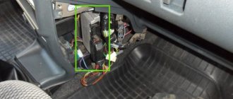
Where is the ECU located on the VAZ 2114
In a VAZ 2114 car, the control module is installed under the center console of the car, in particular, in the middle, behind the panel with the radio. To get to the controller, you need to unscrew the latches on the side frame of the console. As for the connection, in Samar modifications with a one and a half liter engine, the mass of the ECU is taken from the power unit housing, from the fastening of the plugs located to the right of the cylinder head.
Location of the VAZ 2114 ECU
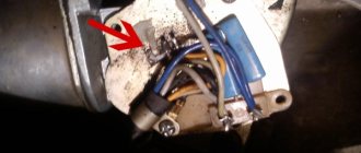
In cars equipped with 1.6- and 1.5-liter engines with a new type of ECU, the mass is taken from the welded stud. The pin itself is fixed on the metal body of the control panel near the floor tunnel, not far from the ashtray. During production, VAZ engineers, as a rule, do not securely fix this pin, so over time it can become loose, which will lead to the inoperability of some devices.
How to find out which ECU is on the VAZ 2114 – January 7.2 January 4 Bosch M1.5.4
Today, there are 8 (eight) generations of electronic control units, which differ not only in characteristics, but also in manufacturers. Let's talk about them in a little more detail.
ECU January 7.2 – technical specifications
And so now we move on to the technical characteristics of the most popular ECU January 7.2
January 7.2 is a functional analogue of the Bosch M7.9.7 block, a “parallel” (or alternative, as you like) domestic development with M7.9.7. January 7.2 is externally similar to the M7.9.7 - assembled in a similar case and with the same connector, it can be used without any modifications on the Bosch M7.9.7 wiring using the same set of sensors and actuators.
The ECU uses a Siemens Infenion C-509 processor (the same as the ECU January 5, VS). The block’s software is a further development of the January 5 software, with improvements and additions (although this is a controversial issue) - for example, an algorithm has been implemented, literally an “anti-shock” function, designed to ensure smoothness when starting and shifting gears.
ECU January 7.2
The ECU is produced (хххх-1411020-82 (32), firmware begins with the letter “I”, for example, I203EK34) and “Avtel” (хххх-1411020-81 (31), firmware begins with the letter “A”, for example, A203EK34) . Both the blocks and the firmware of these blocks are completely interchangeable.
ECUs of series 31 (32) and 81 (82) are hardware compatible from top to bottom, that is, firmware for 8-cl. will work in a 16-cl. ECU, but vice versa - not, because the 8-cl. block “does not have enough” ignition keys. By adding 2 keys and 2 resistors you can “turn” an 8-cell. block of 16 cells. Recommended transistors: BTS2140-1B Infineon / IRGS14C40L IRF / ISL9V3040S3S Fairchild Semiconductor / STGB10NB37LZ STM / NGB8202NT4 ON Semiconductor.
Typical ECU parameters January 7.2 for diagnostics
ECU January-4 - technical specifications
The second serial family of ECMs on domestic cars was the “January-4” system, which was developed as a functional analogue of GM control units (with the ability to use the same composition of sensors and actuators in production) and was intended to replace them.
Therefore, during development, the overall and connecting dimensions, as well as the pinout of the connectors, were preserved. Naturally, the ISFI-2S and “January-4” blocks are interchangeable, but are completely different in circuit design and operating algorithms. “January-4” is intended for Russian standards; the oxygen sensor, catalyst and adsorber were excluded from the composition, and a CO adjustment potentiometer was introduced. The family includes control units “January-4” (a very small batch was produced) and “January-4.1” for 8 (2111) and 16 (2112) valve engines.
ECU January 4 second generation of electronic control unit VAZ 2114
The “Kvant” versions are most likely a development series with J4V13N12 firmware in hardware and, accordingly, in software, are incompatible with subsequent serial controllers. That is, the J4V13N12 firmware will not work in “non-quantum” ECUs and vice versa. Photo of KVANT ECU boards and a regular serial controller January 4
ECU diagram January 4
Features of the ECM: without neutralizer, oxygen sensor (lambda probe), with CO potentiometer (manual CO adjustment), toxicity standard R-83.
Bosch M1.5.4 – technical specifications
The next step was to develop, together with Bosch, an ECM based on the Motronic M1.5.4 system, which could be produced in Russia. Other air flow sensors (MAF) and resonant detonation sensors (developed and produced by Bosch) were used. The software and calibrations for these ECMs were first fully developed at AvtoVAZ.
For Euro-2 toxicity standards, new modifications of block M1.5.4 appear (has an unofficial index “N”, to create an artificial difference) 2111-1411020-60 and 2112-1411020-40, satisfying these standards and incorporating an oxygen sensor, catalytic neutralizer and adsorber.
The brains of the Bosch M1.5.4 ECU
Also, for Russian standards, an ECM was developed for 8-class. engine (2111-1411020-70), which is a modification of the very first ECM 2111-1411020. All modifications, except the very first, use a wideband knock sensor. This unit began to be produced in a new design - a lightweight, leak-proof stamped body with an embossed inscription “MOTRONIC” (popularly “tin can”). Subsequently, ECU 2112-1411020-40 also began to be produced in this design.
Replacing the structure, in my opinion, is completely unjustified - sealed blocks were more reliable. New modifications most likely have differences in the circuit diagram towards simplification, since the detonation channel in them works less correctly, the “tins” “ring” more when using the same software.
Itelma 5.1 - technical characteristics of the VAZ 2114 ECU
NPO Itelma has developed an ECU for use in VAZ cars, called VS 5.1. This is a fully functional analogue of the ECM January 5.1, that is, it uses the same harness, sensors and actuators.
VS5.1 uses the same Siemens Infenion C509, 16 MHz processor, but is made on a more modern element base. Modifications 2112-1411020-42 and 2111-1411020-62 are designed for Euro-2 standards and include an oxygen sensor, catalytic converter and adsorber; this family does not provide R-83 standards for 2112 engines. For 2111 and Russia-83 standards Only ECM version VS 5.1 1411020-72 with simultaneous injection is available.
Itelma 5.1 - technical characteristics of the VAZ 2114 ECU
Since September 2003, VAZ has been equipped with a new HARDWARE modification VS5.1, which is incompatible in software and hardware with the “old” one.
- 2111-1411020-72 with firmware V5V13K03 (V5V13L05). This software is incompatible with software and ECUs of earlier versions (V5V13I02, V5V13J02).
- 2111-1411020-62 with firmware V5V03L25. This software is not compatible with earlier versions of software and ECUs (V5V03K22).
- 2112-1411020-42 with firmware V5V05M30. This software is incompatible with software and ECUs of earlier versions (V5V05K17, V5V05L19).
In terms of wiring, the blocks are interchangeable, but only with their own software corresponding to the block.
Bosch M7.9.7 - ECU technical specifications
The 30 series Bosch was also found on 1.6 liter engines, but due to the initial development for a one and a half liter car, the software was very buggy, sometimes completely refusing to work. A special configuration marked 31h, released a little later, worked much more adequately.
The January seven had many models depending on the configuration and engine size, so on 1.5 liter eight-valve engines models produced by AVTEL were installed with the bar: 81 and 81h, the same brain from the manufacturer ITELMA had the numbers 82 and 82h. Bosch M7.9.7 was installed on 1.5-liter engines of export models and was marked 80 and 80h on Euro 2 cars and 30 on Euro 3 cars.
The brains of the Bosch M 7 ECU
1.6 liter engines of cars intended for the domestic market had on board devices from the same AVTEL and ITELMA. The first series from the first ones, marked 31, suffered from the same problems as Bosch 30 series, later all the shortcomings were taken into account and corrected in 31 hours. Despite problems among competitors, ITELMA has noticeably grown in the eyes of car enthusiasts, releasing a successful series number 32. Additionally, it should be noted that only Bosch M7.9.7 with marker 10 complied with the Euro 3 standard. The cost of a new ECU of this generation is 8 thousand rubles, used can be found at a disassembly site for 4 thousand.
Diagram of the engine control system (ECM) VAZ-2113, 2114 and 2115
Engine control system (ECM) diagram Euro-2 Bosch 7.9.7, January 7.2 VAZ-2113, 2114 and 2115 (2111-1411020-80, 81.82). Engine 1.5 liter 8 valve.
- — controller;
- — block of the ignition system harness to the ABS cabin group harness;
- — diagnostic block;
- — immobilizer warning sensor (APS);
- — immobilizer control unit (APS);
- - ignition coil;
- - spark plug;
- — nozzles;
- — electric fuel pump;
- — block of the ignition system harness to the electric fuel pump harness;
- — block of the fuel level sensor harness to the ignition system harness;
- — block of the ignition system harness to the injector harness;
- — block of the injector harness to the ignition system harness;
- - speed sensor;
- — idle speed regulator;
- — throttle position sensor;
- — coolant temperature sensor;
- — mass air flow sensor;
- — camshaft position sensor (phases);
- — oxygen sensor;
- — crankshaft position sensor;
- - knock sensor;
- — solenoid valve for purge of the adsorber;
- — block of the ignition system harness to the instrument panel harness;
- — controller power supply fuse;
- - ignition relay;
- — ignition relay fuse;
- — fuse for the power supply circuit of the electric fuel pump;
- — electric fuel pump relay;
- — electric fan relay;
- — block of the ignition system harness to the air conditioning harness;
- — pads of the ignition system harness to the front harness;
- — electric cooling system fan;
- — block of the instrument panel harness to the ignition system harness;
- — ignition switch;
- — instrument cluster;
- — on-board control system unit;
- - starter relay;
- — mounting block;
- A - to the “plus” terminal of the battery; B1, B2 - grounding points of the ignition system harness;
2115-3724026-11 — Ignition system harness;
Diagram of the engine control system (ECM) Euro-2 Bosch 7.9.7, January 7.2 VAZ-2113, 2114 and 2115 (21124-1411020-30, 21124-1411020-31.32). 1.6 liter 16 valve engine with individual ignition coils.
- — block of the ignition coil wiring harness to the ignition system harness;
- — block of the ignition system harness to the ignition coil wiring harness;
- — ignition coils;
- — immobilizer warning sensor;
- — immobilizer control unit;
- - spark plug;
- — nozzles;
- — diagnostic block;
- — block of the ignition system harness to the ABS cabin group harness;
- — controller;
- — electric fuel pump;
- — block of the ignition system harness to the fuel level sensor harness;
- — block of the fuel level sensor harness to the ignition system harness;
- — block of the ignition system harness to the injector harness;
- — block of the injector harness to the ignition system harness;
- — block of the ignition system harness to the side door harness;
- - speed sensor;
- — idle speed regulator;
- — throttle position sensor;
- — coolant temperature sensor;
- — mass air flow sensor;
- — oil pressure warning lamp sensor;
- — camshaft position sensor (phases);
- — oxygen sensor;
- — crankshaft position sensor;
- - knock sensor;
- — solenoid valve for purge of the adsorber;
- —
- — coolant temperature indicator sensor;
- — block of the ignition system harness to the instrument panel harness;
- — block of the instrument panel harness to the ignition system harness;
- - ignition relay;
- — ignition relay fuse;
- — fuse for the power supply circuit of the electric fuel pump;
- — electric fuel pump relay;
- — electric fan relay;
- — controller power supply fuse;
- — ignition system harness block to the air conditioner connector;
- — instrument cluster;
- — ignition switch;
- — electric cooling system fan;
- — on-board control system unit;
- — additional starter relay;
- — contacts of the 8-terminal blocks of the instrument panel harness and the front harness;
- — contacts of the 21-terminal blocks of the instrument panel harness and the rear harness;
- - trip computer;
- — diagnostic connector;
- A, E - to the “plus” terminal of the battery; B1 — grounding point of the ignition coil wiring harness; B2 — grounding point of the fuel level sensor harness; B3, B4 - grounding points of the ignition system harness; C - to the starter; D — to the driver's door interior lamp switch;
Diagram of the engine control system (ECM) Euro-3 Bosch 7.9.7+, M73 VAZ-2113, 2114 and 2115 (2111-1411020-30). Engine 1.6 liter 8 valve.
1 - controller; 2 — block of the ignition system harness to the ABS cabin group harness; 3 — diagnostic block; 4 — immobilizer warning sensor (APS); 5 — immobilizer control unit (APS); 6 — ignition coil; 7 — spark plugs; 8 — nozzles; 9 — electric fuel pump; 10 — block of the ignition system harness to the fuel level sensor harness; 11 — block of the fuel level sensor harness to the ignition system harness; 12 — block of the ignition system harness to the injector harness; 13 — injector harness block to the ignition system harness; 14 — speed sensor; 15 — idle speed regulator; 16 — throttle position sensor; 17 — coolant temperature sensor; 18 — mass air flow sensor; 19 — camshaft position sensor (phases); 20 — control oxygen sensor; 21 — crankshaft position sensor; 22 — knock sensor; 23 — solenoid valve for purge of the adsorber; 24 — rough road sensor; 25 — diagnostic oxygen sensor; 26 — block of the ignition system harness to the instrument panel harness; 27 — controller power supply fuse; 28 — ignition relay; 29 — ignition relay fuse; 30 — fuse for the electric fuel pump power supply circuit; 31 — electric fuel pump relay; 32 — electric fan relay; 33 — block of the ignition system harness to the air conditioner harness; 34 — pads of the ignition system harness to the front harness; 35 — electric fan of the cooling system; 36 — block of the instrument panel harness to the ignition system harness; 37 — ignition switch; 38 — instrument cluster; 39 — on-board control system unit; 40 — starter relay; 41 — mounting block;
A - to the “plus” terminal of the battery; B1 — grounding point of the fuel level sensor harness; B2, B3 - grounding points of the ignition system harness;
Diagram of the engine control system (ECM) Euro-3 Bosch 7.9.7+, M73 VAZ-2113, 2114 and 2115 (21124-1411020-10). 1.6 liter 16 valve engine with individual ignition coils and two oxygen sensors.
1 — block of the ignition coil wiring harness to the ignition system harness; 2 — block of the ignition system harness to the ignition coil wiring harness; 3 — ignition coils; 4 — immobilizer warning sensor; 5 — immobilizer control unit; 6 — spark plugs; 7 — nozzles; 8 — diagnostic block; 9 — block of the ignition system harness to the ABS cabin group harness; 10 - controller; 11 — electric fuel pump; 12 — block of the ignition system harness to the fuel level sensor harness; 13 — block of the fuel level sensor harness to the ignition system harness; 14 — block of the ignition system harness to the injector harness; 15 — injector harness block to the ignition system harness; 16 — block of the ignition system harness to the side door harness; 17 — speed sensor; 18 — idle speed regulator; 19 — throttle position sensor; 20 — coolant temperature sensor; 21 — mass air flow sensor; 22 — oil pressure warning lamp sensor; 23 — camshaft position sensor (phases); 24 — control oxygen sensor; 25 — crankshaft position sensor; 26 — knock sensor; 27 — solenoid valve for purge of the adsorber; 28 — diagnostic oxygen sensor; 29 — coolant temperature indicator sensor; 30 — block of the ignition system harness to the instrument panel harness; 31 — block of the instrument panel harness to the ignition system harness; 32 — ignition relay; 33 - ignition relay fuse; 34 — fuse for the electric fuel pump power supply circuit; 35 — electric fuel pump relay; 36 — electric fan relay; 37 — controller power supply fuse; 38 — ignition system harness block to the air conditioner connector; 39 — rough road sensor; 40 — instrument cluster; 41 — ignition switch; 42 — electric fan of the cooling system; 43 — on-board control system unit; 44 - additional starter relay; 45 — contacts of the 8-terminal blocks of the instrument panel harness and the front harness; 46 — contacts of the 21-terminal blocks of the instrument panel harness and the rear harness; 47 — trip computer; 48 — diagnostic connector;
A, E - to the “plus” terminal of the battery; B1 — grounding point of the ignition coil wiring harness; B2, B3 - grounding points of the ignition system harness; B4 — grounding point of the fuel level sensor harness; C - to the starter; D — to the driver's door interior lamp switch;
Source
ECU pinout diagram January 7.2 VAZ 2114
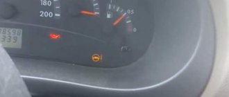
The VAZ 2114 controller often breaks down. The system has a self-diagnosis function - the ECU queries all components and issues a conclusion about their suitability for operation. If any element fails, the “Check Engine” lamp will light up on the dashboard.
ECU pinout diagram January 7.2
It is possible to find out which sensor or actuator has failed only with the help of special diagnostic equipment. Even with the help of the famous OBD-Scan ELM-327, loved by many for its ease of use, you can read all engine operating parameters, find the error, eliminate it and delete it from the memory of the VAZ 2114 ECU .
How to independently diagnose the unit?
At first glance, it may seem that diagnosing an ECU is a difficult task that not everyone can handle. Indeed, checking your block is not so easy, but having theoretical knowledge, it is quite possible to apply it in practice.
Required tools and equipment
To check the functionality of the module yourself, you will need to perform a number of steps to connect to the ECU.
To perform the test you will need the following devices and elements:
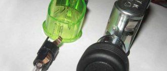
- Oscilloscope. It’s clear that not every car enthusiast has such a device, so if you don’t have one, you can use a computer with the necessary diagnostic software pre-installed on it.
- Cable for connecting to the device. You need to select an adapter that supports the KWP2000 protocol.
- Software. Finding diagnostic software today is not a problem. To do this, just monitor the network and find a program that is suitable for your vehicle. The program is selected taking into account the car, since different control units are installed on different cars.
Photo gallery “Preparing for system diagnostics”
Algorithm of actions
The diagnostic procedure for the electronic control system is discussed below using the Bosch M 7.9.7 module as an example. This control unit model is one of the most common not only in domestic VAZ cars, but also in foreign-made cars. It should also be noted that the verification process is described using the example of using the KWP-D software.
So, how to check the ECU at home:
- First of all, the adapter used must be connected to a computer or laptop, as well as the ECM itself. To do this, connect one end of the cable to the output on the unit, and the other to the USB output on the computer.
- Next, you need to turn the key in the car's ignition, but you do not need to start the engine. By turning on the ignition, you can launch the diagnostic utility on your computer.
- After completing these steps, a window with a message should pop up on the computer screen, which confirms the successful start of diagnosing malfunctions in the controller. If for some reason the message does not appear, you need to make sure that the computer successfully connected to the controller. Check the quality of the connection and connection of the cable to the unit and laptop.
- Then a table should be displayed on the laptop display, which will indicate the main technical characteristics and operating parameters of the vehicle.
- At the next stage, you need to pay attention to the DTC section (it may be called differently in different programs). This section will present all the faults with which the power unit operates. All errors will be displayed on the screen in the form of encrypted combinations of letters and numbers. To decipher them, you need to go to another section, which is usually called Codes, or use the technical documentation for your car.
- If there are no errors in this section, then you now don’t have to worry, since the vehicle’s engine is working perfectly (the author of the video about ECU repair at home is the AUTO REZ channel).
But this verification option is most relevant if the computer sees the block. If you have problems connecting to it, then you will need an electrical diagram of the device, as well as a multimeter. The tester or multimeter itself can be purchased at any specialty store, and the electrical circuit diagram of the ECM should be in the service manual. The diagram itself needs to be studied most carefully; this will be required for verification.
In the event that the ECM points to a specific block, and does not show erratic data, then in accordance with the diagram it needs to be found and called. If there is no accurate information, then the only way out is to diagnose the entire system; as we said above, breakdowns are considered one of the main faults.
After the breakdown is found, it is necessary to check the resistance and determine exactly where the cable is fixed. You will need to solder the corresponding new wire parallel to the old one; if the reason lies in the breakdown, then these actions will eliminate the problem. In all other cases, only qualified specialists can solve the problem.
VAZ 2114 ECU burned out - what to do?
One of the common malfunctions of the ECU (electronic control unit) on the fourteenth is its failure or, as people say, combustion.
Obvious signs of this breakdown will be the following factors:
- Lack of control signals for injectors, fuel pump, valve or idle mechanism, etc.
- Lack of response to Lambda - regulation, crankshaft sensor, throttle valve, etc.
- Lack of communication with the diagnostic tool
- Physical damage.
In these cases, it is recommended to purchase a new ECU and replace the faulty one. How to do this is very simple!
Frequent malfunctions of the VAZ electronic control unit
Considering that the controller is a complex electronic device, failure of the ECU cannot be ruled out. As a rule, the causes of ECU malfunction can be different, ranging from mechanical damage to software failures.
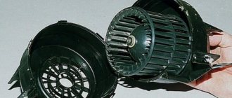
For example, a common cause of breakdowns is overheating or liquid ingress. As practice shows, on the Lada Samara the ECU is located near the heater radiator. It is not difficult to guess that a radiator leak and coolant entering the controller often disables this device.
In this case, the check engine light does not always light up on the panel, but the engine malfunctions. In such a situation, when no other causes have been identified, what is needed is not diagnostics of the engine and systems, but professional diagnostics of the car's ECU, which can only be performed by an experienced specialist. Often, after checking, the unit may need to be replaced, since ECU repair is often not recommended.
How to remove and replace a faulty ECU on a VAZ 2114
When carrying out work to remove the VAZ 2114 ECU, do not touch the terminals with your hands. There is a possibility of damage to electronics due to electrostatic discharge.
- Using a screwdriver, unscrew the 3 screws securing the right panel of the instrument panel console and remove it.
- Release the clamp of the block with wires
- Disconnect the block from the ECU.
- Using a 10mm wrench, unscrew the 4 nuts securing the ECU to the bracket.
- We move the ECU forward and remove it from under the console.
- Remove the ECU from the bracket.
- Reinstall the ECU in reverse order.
Methods for resetting an ECU with initialization.
With certain skills, the EPROM unit can be reprogrammed, which will improve the power and dynamics of the VAZ 2114. Methods for resetting the ECU with initialization. I will tell you about the methods for resetting the ECU in this video - watch to the end. All ECUs made according to Euro2 standards and higher (i.e. systems with feedback, i.e. with an oxygen sensor) are self-learning, be it Bosch or January. Only Y5.1.1 and Y5.1.2 and the corresponding Bosch M1.5.4 are not trained. to P83 standards.
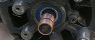
Where is the mass of the VAZ 2114 ECU located?
The first ground pin from the ECU on cars with a 1.5 engine is located under the instruments on the power steering shaft mount. The second terminal is located under the instrument panel, next to the heater motor, on the left side of the heater housing.
Location of the mass of the VAZ 2114 ECU
On cars with a 1.6 engine, the first terminal (mass of the VAZ 2114 ECU) is located inside the dashboard, on the left, above the relay/fuse block, under the sound insulation. The second terminal is located above the left screen of the center console of the instrument panel on a welded stud (fastened with an M6 nut).
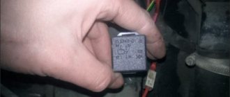
Where is the relay and fuse of the VAZ 2114 ECU located?
The main part of the fuses and relays is located in the mounting block of the engine compartment, but the relay and fuse responsible for the electronic control unit of the VAZ 2114 are located in a different place.
Relays and fuses of the VAZ 2114 computer
The second “block” is located under the dashboard on the front passenger side. To access it you just need to unscrew a few fasteners using a Phillips screwdriver. Why is it in quotes, because there is no such block, there is an ECU (brains) and 3 fuses + 3 relays.
What to do if the scanner does not see the VAZ 2114 ECU
Reader question: Guys, why does it say during diagnostics that there is no connection with the ECU? What to do? What to fix?
So, why doesn’t the scanner see the VAZ 2114 ECU? What should I do so that the device can connect and see the block? Today you can find many different adapters for testing a vehicle on sale.
If you buy an ELM327 Bluetooth, most likely you are trying to connect a low-quality device. Or rather, you could have purchased an adapter with an outdated version of the software.
Car diagnostics using a scanner
So, for what reasons does the device refuse to connect to the block:
- The adapter itself is of poor quality. Problems can be with both the device’s firmware and its hardware. If the main microcircuit is inoperative, it will be impossible to diagnose the engine operation, as well as connect to the computer.
- Bad connection cable. The cable may be broken or inoperative itself.
- The wrong version of the software is installed on the device, as a result of which it will not be possible to achieve synchronization (the author of the video about testing the device is Rus Radarov).
In this case, if you are the owner of a device with the correct firmware version 1.5, where all six of the six protocols are present, but the adapter does not connect to the ECU, there is a way out. You can connect to the unit using initialization strings, which allow the device to adapt to the commands of the machine’s motor control unit. In particular, we are talking about initialization lines for diagnostic utilities HobDrive and Torque for vehicles that use non-standard connection protocols.
ECU diagnostics
The VAZ engine control unit is a device that can operate for a long time without breakdowns, however, no equipment can be protected from malfunctions. When the first symptoms of failure are detected, the device must be diagnosed, since untimely inspection and repair can lead to more serious consequences. Device diagnostics involves reading error codes stored in the device’s memory for further decryption.
It is best to check the ECU in specialized centers, since the diagnostic equipment must be configured for a specific ECU model. Of course, the diagnostic procedure can be carried out on your own - using a computer, diagnostic adapter and software.
In the event that the ECU does not respond to the test, its performance should be checked, in particular:
- diagnose the device for overheating;
- make sure that the device is connected to the power circuit and that its contact with the on-board network is good;
- diagnose the mechanical integrity of the device - it is quite possible that there is damage to the device body, or the reason may be the formation of corrosion.
Remember that it is impossible to perform high-quality repairs of the control unit at home . It is better to entrust the repair procedure to specialists, and not from any service station, but from certified centers.
Photo gallery “Do-it-yourself ECU replacement”
1. The block is fixed using a special strip; it should be bent.
2. Next, unscrew the nuts that secure the block to this bar.
3. When the nuts are unscrewed, the bar moves slightly to the side, this will allow you to dismantle the computer.
Loading …
Voltage disappears on the VAZ 2114 ECU - what to do
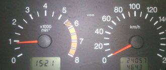
Reader question: Hello everyone, please help me with the problem. The symptoms are as follows: 1. Error 1206 appears - on-board network voltage interruption. In cold weather, starting the engine is generally a problem - it takes a few seconds, a click sounds like a relay is triggered, the speed jump check light comes on and the car stalls. This can go on for half an hour, and the car may stall while driving. When the engine warms up, the loss stops. Where can I look for the cause of what kind of sensor might have gone missing? Thanks in advance!
Error voltage loss VAZ 2114
In principle, there can be many solutions to this problem:
- If the voltage on the battery is less than 12.4 volts, then the ECU begins to save energy, at 11 you may not even be able to start it on a cord))) The ECU sometimes sees a voltage less than what is actually on the battery, this usually indicates that it’s time to clean the ECU mass, Look into the connector and wipe the contacts. In your case, when it’s cold it’s a problem, when it’s hot everything’s fine. And if you look from the battery side? When hooked, the problem is, when recharged, everything is fine. A good diagnostician will not harm the machine
- I also recommend paying attention to the malfunction: ignition coil, ignition module, contactless spark plug ignition switch.
Well, that’s it, dear friends, our article about the VAZ 2114 ECU has come to an end. Still have questions? Be sure to ask them in the comments!