Complete information is provided about electrical equipment, wiring, relays and fuses of VAZ-2170 - VAZ-21728 vehicles. The collection is intended for auto electricians and those who, having some knowledge of circuit design, can carry out minor auto repairs with their own hands. The Lada Priora sedan (VAZ-2170) has been produced since 2007, the VAZ-2172 hatchback since 2008, and the VAZ-2171 station wagon has been produced since 2009. In 2013, the car was modernized and they began installing an AMT robotic gearbox (21723, 21728).
There are 4 main harnesses in the Priora electrical circuit:
- from the instrument panel;
- providing motor control;
- front electrical harness;
- rear electrical harness.
All these harnesses are connected to each other using detachable connections. The connectors are located under the dashboard. Each of the harnesses is assigned a serial number.
In addition to the main ones, there are also secondary ones:
- installed in the front passenger door;
- identical in both the left and right rear doors;
- installed in the driver's door;
- connecting the backlight of the license plate;
- connecting the electrical package.
Each element in the diagram corresponds to a number with an explanation. Since all elements are standardized, their designations are identical on car diagrams of all car manufacturers. Next to each electrical appliance, the connectors that go to them are indicated. The pins or sockets of the pads are also numbered.
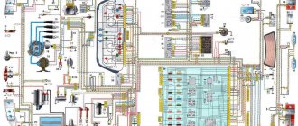
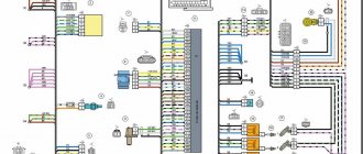
Lada Priora wiring block diagrams
1,2,3,4 – blocks of the instrument panel wiring harness to the blocks of the rear wiring harness; 5 – block of the instrument panel wiring harness to the block of the ignition system wiring harness; 6,7,8 – blocks of the instrument panel wiring harness to the blocks of the front wiring harness; 9 – lighting control module; 10 – ignition switch; 11 – on-board computer mode switch; 12 – windshield wiper switch; 13 – passenger airbag module; 14 – light signaling switch; 15 – instrument cluster; 16 – hours; 17 – diagnostic block; 18 – recirculation switch; 19 – control unit for windshield wiper and external lighting; 20 – micromotor gearbox for driving the heater control damper; 21 – rear window heating switch; 22 – alarm switch; 23 – brake signal switch; 24 – electric amplifier control unit; 25,26 – blocks of the instrument panel wiring harness to the radio; 27 – mounting block: K1 – relay for turning on low beam headlights and side lights; K2 – relay for turning on the heated rear window; K3 – starter activation relay; K4 – additional relay; K6 – relay for turning on the high speed windshield wiper (automatic mode); K7 – headlight high beam relay; K8 – sound signal relay; K9 – relay for turning on the alarm sound signal; K10 – relay for turning on fog lights; K11 – relay for turning on the electric heating of the front seats; K12 – windshield wiper activation relay (intermittent and automatic modes). 28 – lampshade lighting of the glove box; 29 – glove box lighting switch; 30 – automatic lighting control switch; 31 – electrical package controller; 32 – controller of the automatic climate control system; 33 – rotating device; 34 – driver airbag module; 35 – sound signal switch.
1 – oil pressure warning lamp sensor; 2 – coolant temperature indicator sensor; 3 – main fuse block; 4 – controller power supply fuse (7.5 A); 5 – fuse for the power supply circuit of the electric fuel pump (15 A); 6 – ignition relay fuse (15 A); 7 – Priora ignition relay; 8 – electric fuel pump relay; 9 – throttle position sensor; 10 – idle speed regulator; 11 – coolant temperature sensor; 12 – ignition system harness block to the instrument panel harness block; 13 – solenoid valve for purge of the adsorber; 14 – speed sensor; 15 – mass air flow sensor; 16 – crankshaft position sensor; 17 – diagnostic oxygen sensor; 18 – Priora Lada controller; 19 – rough road sensor; 20 – control oxygen sensor; 21 – pads for the ignition coil harness and ignition system harness; 22 – ignition coils; 23 – spark plugs; 24 – Lada Priora injectors; 25 – phase sensor; 26 – knock sensor; 27 – pads of the ignition system harness and injector harness.
1 – right headlight; 2 – right front speed sensor; 3 – reverse light switch; 4 – electric motor for washers; 5 – windshield wiper motor; 6 – engine compartment lamp switch; 7 – electric fan of the engine cooling system (left); 8 – starter 2170; 10 – rechargeable battery; 11 – main fuse block; 12 – VAZ2170 generator; 13 – ABS hydraulic unit; 14 – air temperature sensor; 15 – brake fluid level sensor; 16 – alarm signal; 17 – sound signal; 18 – left front speed sensor; 19,20,21 – front wiring harness blocks to the instrument panel wiring harness blocks; 22 – left headlight VAZ-2170; 23 – right fog lamp; 24 – left fog lamp; 25 – air conditioning system pressure sensor; 26 – air conditioning compressor; 27 – air conditioner electric fan (right); 28 – air temperature sensor (air conditioning system); 29 – rear window washer electric motor; 30 – block of the front wiring harness to the block of the heater wiring harness; 31 – right electric fan relay; 32 – left electric fan relay; 33 – additional relay (sequential activation of left and right electric fans); 34 – heater electric fan relay; 35 – compressor relay; 36 – compressor power supply fuse (15 A); 37 – fuse for the power supply circuit of the electric heater fan (40 A); 38 – front wiring harness block to rear wiring harness block; 39 – fuse for the power supply circuit of the right electric fan (30 A); 40 – fuse for the power supply circuit of the left electric fan (30 A).
1 – rear wiring harness block to the instrument panel wiring harness block; 2 – rear wiring harness block to additional wiring harness block 2 (left rear door); 3 – rear wiring harness block to side door wiring harness block (right front door); 4 – left side direction indicator; 5 – electrical package controller; 6 – right side direction indicator; 7 – interior lighting unit; 8 – handbrake warning lamp switch; 9 – left lamp of Lada Priora; 10 – right lamp; 11 – interior air temperature sensor; 12 – interior lamp switch in the driver’s door pillar; 13 – switch for the interior lighting in the pillar of the right front door; 14 – switch for the interior lighting in the pillar of the right rear door; 15 – interior light switch in the left rear door pillar; 16 – block of the rear wiring harness to the block of the wiring harness of the side doors 2 (left front door); 17 – rear wiring harness block to the additional wiring harness block (right rear door); 18 – blocks of the rear wiring harness to the rear right loudspeaker; 19 – blocks of the rear wiring harness to the rear left loudspeaker; 20 – cigarette lighter VAZ-2170; 21 – electric fuel pump module; 22, 23 – rear wiring harness blocks to instrument panel wiring harness blocks 2,3; 24 – trunk lighting; 25 – additional brake signal; 26 – trunk lock drive switch; 27 – interior lamp; 28 – rear wiring harness block to the front wiring harness block; 29 – left rear speed sensor; 30 – right rear speed sensor; 31 – sensor for automatic glass cleaning system (rain sensor); 32 – rain sensor sensitivity regulator; 33 – rear wiring harness block to instrument panel wiring harness block 4; 34 – block of the rear wiring harness to the block of the wiring harness of the parking system sensors; 35 – alarm unit for safe parking system; 36 – driver’s seat belt pretensioner; 37 – passenger seat belt pretensioner; 38 – rear wiring harness block to side door wiring harness block 3 (right front door); 39 – airbag control unit; 40 – parking system control unit; 41 – block of the rear wiring harness to the block of the rear additional wiring harness (tailgate); 42 – rear wiring harness block to rear additional wiring harness block 2 (tailgate); 43 – left seat heater; 44 – switch for electric seat heaters; 45 – right seat heater. 46 – rear wiring harness block to the parking system switch.
Useful: Sensor with car washer fluid level indicator
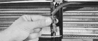
Checking the regulator for functionality
To diagnose DTOZH at home, you will need a separate container with antifreeze, as well as a thermometer that can record temperatures up to 120 degrees. Checking is carried out using a tester. In particular, you need to measure the resistance at different temperatures of the liquid (the liquid must be heated during diagnostics), and the obtained data is checked against the temperature.
At 100 degrees, the resistance of the device should be 177 ohms, at 90 degrees - 241 ohms, at 80 - 332 ohms. At an engine temperature of 0 degrees, the resistance level will be 7280 Ohms, at 40 degrees – 1459 Ohms. This data will be sufficient for diagnostics.
Instrument cluster block diagram
| № | Decoding |
| 1 | Electric power steering |
| 2 | Emergency gang control VAZ-2170 |
| 3 | Connection to oil pressure sensor |
| 4 | Parking brake indicator light |
| 5 | Electronic anti-theft device |
| 6 | Airbag control module |
| 7 | External lighting switch |
| 8 | Right turn signal indicator and doubler |
| 9 | Left turn signal indicator and backup |
| 10 | Engine control unit |
| 11 | Disabling the passenger's front airbag |
| 12 | Seat belt warning light |
| 13 | ABS brake system unit |
| 14 | Steering column switch button |
| 15 | Brake expansion tank indicator |
| 16 | ABS safety control module |
| 17 | Main beam headlight control unit |
| 18 | Shield backlight module |
| 19 | General disadvantage of the device |
| 20 | Constant positive battery terminals |
| 21 | Ignition switch contact |
| 22 | Fuel flow meter |
| 23, 24 | Steering wheel turn switches |
| 25,26 | Overboard temperature sensors |
| 27 | Fuel sensor VAZ-2170 |
| 28 | Speed sensor |
| 29 | Coolant temperature sensor |
| 30 | Tachometer signal |
| 31 | Shield diagnostics |
| 32 | Generator Regulator Relay Terminal |
Electrical connection diagram for heater wiring harness PRIORA 21723
- heater wiring harness block to the front wiring harness block;
- air mixing gearmotor;
- evaporator temperature sensor;
- electric fan 2172;
- speed controller;
- recirculation gearmotor.
Parking system sensor diagram 2172-3724248
1,2,3 – parking system sensors; 4 – block of the wiring harness of the parking system sensors to the block of the rear wiring harness.
Rear license plate light pinout
1. Supply voltage to the lights illuminating the rear number 2,3. Priora 4 license plate lamps. Electric trunk lid locking motor
Electrical circuit operation
It runs on a gasoline engine with electronic ignition, and the power system of the Lada Priora is injection. Correct fuel supply is carried out thanks to an electrical controller, and the mixture is ignited using a regular spark. All other components of the Priora are not paramount, since they are designed to provide factors such as safety and comfort while driving. In general, the VAZ scheme is divided into 2 categories:
The electrical wiring diagram is based on detachable connections, due to which, in a fairly short period of time, not only diagnostics of any Priora breakdowns is carried out, but also troubleshooting.
Lighting control unit diagram
| G, 56b | To the gear motor for adjusting headlights |
| 58b | Output to backlight sources |
| 31 | Mass (ground) |
| Xz | +12 volts (from terminal 15 of the ignition switch) |
| 56 | To the relay for switching high and low headlights |
| 1,3 | From rear and front fog lights |
| 2,4 | To the rear and front fog lamp relays |
| 58 | For lamps of Lada Priora dimensions |
| 30 | +12 V from terminal No. 30 of the ignition switch |
Imported or domestic
Imported analogues of bearings have a slightly different designation, namely:
Most 80-amp generators have bearings of similar sizes, at least this applies to domestic ones. If the generator has already been replaced before you, then you may be faced with the fact that a generator from a different manufacturer is installed and the bearings are of different sizes. Depending on the generator manufacturer, bearings of other sizes are sometimes found, for example, in the fairly common Bosch 14V 53-98A 0124 415 038 generator, bearings 6003-2RS (rear) are installed, the dimensions of which are 17 × 35 × 10 and 6303-2RS (front) , respectively, 15×35×14. The same bearings can be found in other imported generators. However, there are options where the rear bearing is designated as 6000-2RS, and the front bearing – 6203-2RS.
In order to accurately determine the dimensions of the bearing, it will have to be removed. If the markings on the bearing are not visible, then it is best to turn to professionals (you should not trust a caliper).
If you have decided on the size of the bearing, then to the repeated question “What bearings are on the VAZ-2110?” The answer suggests itself - original!
The quality of bearings varies from manufacturer to manufacturer; some prefer to install bearings from domestic manufacturers on their generators, while others prefer imported ones. When repairing a generator, everyone decides this issue for themselves, but after listening to numerous tips, some car enthusiasts are inclined to choose imported ones. If you focus on price-quality ratio, many experts recommend DAS LAGER Germany. But there are other suppliers of quality bearings: the French company SNR; FAG is one of the leading companies in Germany; NSK is another major bearing manufacturer from Japan; NTN – Japan; Kouo - part of the Toyota concern of Japan; Kraft or BOSCH.
We also supply bearings from Chinese manufacturers, but the attitude of motorists towards generators and bearings from the Middle Kingdom is far from flattering. A bearing is considered original if it is approved by the vehicle manufacturer for sale on the market. It usually corresponds to what is (or was previously) supplied to the assembly line. The car manufacturer guarantees that these bearings will not let you down.
If you are considering various options, then all the bearings with the corresponding markings at first glance look the same, but after opening the package, you need to pay attention to the marking, which, in addition to the designation of the bearing itself, consisting of digital and letter designations, must contain an indication of the manufacturer and necessarily the country of origin. If this is not the case, then it is quite possible that it is a fake. In this case, the money lost will not be that big (most often up to 100 rubles per bearing)
But you will lose significant time and nerves
In this case, the money lost will not be that big (most often up to 100 rubles per bearing). But you will lose significant time and nerves.
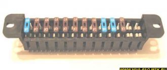
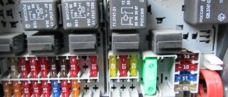
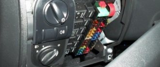
Priora relay and fuse blocks
Location of relays and fuses in the DELRHI 15493150 mounting block
Location of relays and fuses in the mounting block 1118-3722010-00
Lada Priora relay - purpose
K1 Relay for turning on low beam and side lights of headlights (automatic lighting control system) K2 Relay for turning on heated rear window K3 Relay for turning on starter K4 Additional relay K5 K6 Relay for turning on high speed (automatic mode) windshield wiper K7 Relay for turning on high beam headlights K8 Relay for turning on sound signal K9 Relay for turning on the sound alarm signal K10 relay for turning on the fog lights K11 relay for turning on the electric heating of the front seats of the headlights
Lada Priora fuses - purpose
F1
Reserve
F2 (25 A)
Mounting block, relay for turning on the heated rear window (contacts) Electrical package controller, contact “10” of the XP2 block Rear window heating element
F3 (10 A)
Right headlight, high beam lamp Instrument cluster, high beam headlight indicator
F4 (10 A)
Left headlight, high beam lamp
F5 (10 A)
Mounting block, horn relay Horn
F6 (7.5 A)
Left headlight, low beam lamp
F7 (7.5 A)
Right headlight, low beam lamp
F8 (10 A)
Mounting block, alarm horn relay Sound alarm signal
F9
Reserve
F10 (10 A)
Instrument cluster, pin “20” Brake light switch Brake light lamps Interior lighting unit Interior lighting lamp Threshold lamp, right front doors Additional brake light
F11 (20 A)
Mounting block, windshield wiper high speed relay Wiper and washer switch, terminal “53a” Wiper and washer switch, terminal “53ah” Rear window heated switch Mounting block, rear window heated relay ( winding) Windshield wiper motor Rear window wiper motor (2171, 2172) Windshield washer motor Rear window washer motor (2171, 2172) Airbag control unit, pin “25”
F12 (10 A)
Instrument cluster, pin “21” Electrical accessories controller, contact “9” of the block X2 Electromechanical power steering control unit, contact “1” of the block X2 Reversing light switch Reversing light bulbs Parking system control unit, contacts “11” and “14”
F13 (15 A)
Cigarette lighter
F14 (5 A)
Side light lamps (left side) Instrument cluster, main light switch indicator License plate lights Trunk light Electrical package controller, pin “12” of block X2
F15 (5 A)
Side light lamps (right side) Storage lamp box
F16 (10 A)
Hydraulic unit, contact “18”
F17 (10 A)
Left fog light
F18 (10 A)
Right fog light
F19 (15 A)
Seat heating switch, contact “1” Front seat heaters
F20 (10 A)
Switch recirculation (switch on) Mounting block, relay for low beam headlights and parking lights (automatic lighting control system) Heater electric fan relay Automatic lighting control switch Windshield wiper and external lighting control unit, contacts “3”, “11” Automatic climate control system controller , pin “1” Automatic windshield wiper sensor (rain sensor), pin “1”
F21 (5 A)
Light switch, pin “30” Diagnostic deck, pin “16” Clock Automatic climate control system controller, pin “14” "
F22 (20 A)
Windshield wiper motor (automatic mode) Mounting block, windshield wiper relay and high speed windshield wiper relay, (contacts)
F23 (7.5 A)
Wiper and exterior lighting control unit, contact " 20”
F24-F30
Reserve
F31 (30 A)
Electrical package controller, terminal “2” of the block X1 Electrical package controller, terminal “3” of the block X1 Driver’s door module, pin “6” Threshold light of the left front door
Reserve F32
How to determine the malfunction?
If you notice that there are problems with the wiring of the Priora or one of the devices is not functioning, then you can diagnose the voltage using a multimeter. In particular, you will need to check whether there is voltage in the power circuit connecting the failed device to other devices.
How to do it correctly:
- First you need to switch the tester to voltmeter mode.
- Next, one tester probe is connected to the battery or vehicle body, depending on where the device being diagnosed is located.
- The second probe of the device must be connected to the supply cable in the circuit being diagnosed, but before this the terminals from the device must be removed.
- If, during diagnostics, readings appear on the tester screen, this indicates that there is voltage in the circuit, and accordingly, the tested wires are in good condition.
- Similar actions are performed with the remaining wires that require checking. If you eventually find a point where there is no voltage, then this indicates that the source of the breakdown is located in this section of the circuit. The only thing left to do is to simply find the cause and get rid of it (the author of the video is the PRO.Garage channel).
If there is no voltage in the circuit at all, you can diagnose a possible short circuit.
To do this, follow these steps:
- First, you need to remove the part that is responsible for the circuit being diagnosed from the fuse block.
- As in the previous case, the multimeter should be activated in voltmeter mode.
- One tester probe should be connected to the safety element connection outputs. Make sure that all other equipment and devices in this circuit are not connected.
- Then move the wire itself a little - if at this moment indicators appear on the display, this indicates that the wire has a short somewhere. The problem must be solved as quickly as possible - qualified electricians say that in principle it is not worth bringing the electrical circuit to such a state.
Read more: Honda SRV or Hyundai Tussan
A short circuit usually appears in that section of the circuit where the insulation has worn off. This procedure can be carried out with any component of the electrical circuit, as well as with switches. If the diagnostics showed the absence of a short circuit, then there is another test option.
In particular, we are talking about searching for a possible break in the electrical network, the procedure is performed as follows:
- First you need to turn off the power to the on-board network or just one area that you want to check. To do this, either disconnect the terminals from the battery, or simply remove the safety device from its mounting location.
- Now we proceed directly to the test - the tester probes should be connected to the two ends of the electrical circuit section.
- Next, one of the probes should be connected to the car body; you need mass.
- If, at the time of connection, indicators begin to appear on the tester’s display, this indicates that there are no breaks in this section of the electrical circuit. If there are no changes, then we can say with confidence that there is a break in the wiring.
Repair of the ICC
To repair the light control unit, you only need a little skill in using a soldering iron, the soldering iron itself and solder.
To repair the light unit, it must be dismantled.
Remove the fuse box cover by turning the three fasteners 90°.
We unscrew the screw securing the MUS, take it out and disconnect it from the chip.
Disassembling the module
Pull the switch up and remove it, then use a screwdriver to pry up the bottom of the switch and remove it.
Reasons for the breakdown of the ICC
As it would seem, the failure of the light control module on a Priora depends on the number of times the headlights are turned on and off, but this is not the case. Most breakdowns occur not due to the physical impact of a person on a given electrical appliance, but precisely due to the load from constantly switched on headlights. How is this explained?! Driving for a long time with the headlights on provokes heating of the tracks in the MUS board, thereby, when the electrical wiring heats up, its resistance increases and these tracks break.
Priora with daytime running lights
This problem occurs quite often and most prior managers run to the store and buy a new module at a very expensive price. Never rush into buying an ICC as it can be repaired without spending a penny.
If the light control module fails on the road, then you can read how to turn on the lights when the MUS is not working on a Priora here.