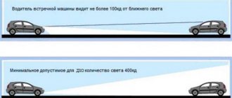
Fog lights are designed to generate a flat and wide stream of light directed above the road surface. This direction of the light beam allows minimizing illumination of the volume of fog in thickness and improves visibility from the driver’s seat. Failure to follow the rules and wiring diagram for fog lights when installing them yourself can lead to accidents.
Requirements for installing fog lights
It is permissible to locate fog lamps directly in the headlights.
The rules for installing headlights are regulated by two regulations:
- GOST 8769-75 or SEV standard 4122-83;
- state standard of the Russian Federation GOST R 41.48-2004, corresponding to UNECE Rules No. 48.
Location of fog lights on a car
The general requirements are as follows:
- The installation location is located at a distance of no more than 400 mm from the side surface of the vehicle body. The distance is measured between the side plane and the outside of the headlight.
- It is permissible to install only two fog lights. The standards separately stipulate the mandatory installation of fog lights on tourist buses, as well as on vehicles operated on mountain roads.
- The lower edge of the fog lighting device is located at a distance of at least 250 mm from the road surface.
- Fog lights should have a horizontal viewing angle ranging from +15º to -10º, and a vertical viewing angle from +45º to -10º. It is unacceptable to block the headlights with vehicle parts within the specified angles.
- Fog lights must be connected in parallel with side lights.
- The lenses of the fog lamps must produce a beam of light located below the flow given by the low beam lamps.
- It is acceptable to use transparent filters or selective yellow color. It is unacceptable to use glass of different colors on the same car.
The standards do not have special requirements for installing fog lights on a car, so the owner can install the kit himself.
What will you need to install fog lights?
To install fog lights yourself, a minimum set of tools is required. The car owner must have knowledge and skills in working with electrical wiring, since the safe operation of the car as a whole depends on the correct installation.
- color electrical diagram of the car;
- nippers or side cutters;
- wire cleaning knife;
- terminal crimping pliers (terminal block);
- soldering iron
Set of materials required for installation:
- a set of fog lights suitable for installation in standard holes in the bumper or universal ones that are mounted on the surface of the bumper;
- stranded copper wire with a cross-section of 1.5-2 mm² with insulation capable of operating at low temperatures and resistant to gasoline and oil vapors;
- relay for turning on (standard headlight turn-on relays from front-wheel drive VAZ models are usually used);
- remote housing for installing a blade fuse;
- 30 A blade fuse;
- a control key that matches the interior design (preferably with a backlight);
- connectors and terminals for connecting wires to circuit elements;
- heat shrink tube of suitable diameter;
- electrical tape on a polyethylene or fabric basis;
- plastic ties;
- automotive corrugated hose for laying wires.
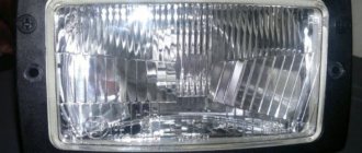
Set of fog lights for Ford Focus 3
Installation and connection of front and rear PTFs on VAZ 2113, 2114, 2115
Before you begin installing fog lights, you will need to select a certain list of tools and additional elements. You can purchase a ready-made connection kit or select the necessary spare parts separately. When everything is prepared, you can mark on the front bumper a place for installing future headlights. The VAZ 2115 comes with standard holes from the factory, but in the case of the VAZ 2113 and VAZ 2114 you will need to work with a tool (a jigsaw or a drill). If you don’t want to damage the bumper, you can install the lighting fixtures on special brackets.
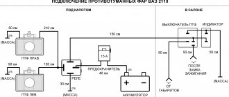
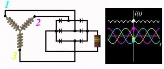
Connection diagram
For installation, two connection schemes for fog lights are possible:
When connected in parallel, the positive wire goes to each headlight from the relay contact. Power to the relay is supplied through a fuse link with a rating of 15 A, which is enough for most models of fog lights. It is advisable to place the fuse as close to the battery terminal as possible.
The +12V signal voltage should appear only when the ignition is active. This measure prevents the headlights from working when the engine is off. If desired, you can automatically ignite the headlights after turning on the ignition. To do this, the signal wire is connected to the battery charging indicator lamp installed in the instrument cluster. The button must be on.
Parallel connection
Serial connection reduces current consumption and lamp brightness. A similar scheme is used to use fog lights instead of standard headlights.
see also
Comments 29
I'll tell you which ones later
I connected the wires and they also get hot
Hello I have a VAZ 2112, I want to change the instrument panel From Priora I can’t find the exact connection diagram Please send the diagram Thank you in advance
It’s easier to take it to an electrician)) and it’s a molorik))!
I connected everything according to your diagram. But my front PTFs don’t work. I don’t know why. And when I rearranged the main wires (Fig. 1), I was left with green wire 56. It went along the old block to the front PTF. But on the new PTF button there is no longer room for this wire. Where did you connect it?
Having connected according to your diagram (low and side) I got this - when you turn on the side, the ignition and side turn on, there is no front... maybe I mixed something up... I can’t figure it out ((((
Look at contacts 58,X X-ignition is on 58-gabor 30-constant plus When the button is turned on, the ignition goes from 30 to 58 and the side light is ON When power comes to X, you can turn on the low beam and the power goes to 56, the low beam turns on
Having connected according to your diagram (low and side) I got this - when you turn on the side, the ignition and side turn on, there is no front... maybe I mixed something up... I can’t figure it out ((((
the problem was in contacts 5 and 6, I swapped them and everything worked
very useful information, I will try your scheme and connect over the weekend)
Guys, thank you very much for the information, the diagrams really saved me! I'm replacing the 2112 panel with a Euro one, using viburnum as the donor. The tidy is already connected, button crap with 10 is difficult to redo without pads
The circuits are real, I developed them myself for two weeks, by mistake and error, everything was connected in my previous car, everything worked like stock.
And were the button lighting illuminated when the dimensions and low/high beams were on?
Yeees! The backlight did not turn off after turning on the dimensions until the dimensions were turned off =)
Do your double button lights come on after ignition?
no, when you press the taillights button, all the interior lights and the parking lights in the front and rear come on.
Well, there’s a feature of these buttons - you turn on the ignition and the button icons of the double button are highlighted, that’s what pin 4 is there for
haha, what a feature in a Russian car)) it’s illumination of the buttons, as well as the instrument panel, heater and cigarette lighter flaps, as well as the inclusion of side lights in the front and rear headlights. And after turning the key, you turn on the ACC function - this is the fuel pump, there is a backlight on the route computer or computer, a light in the driver's compartment, the ability to lower and raise the windows.
There is no trick in a Russian car, just like in foreign cars, after turning the size button on the turn signal brush, we turn on the backlight.
But if everything suits you, then let it remain that way. It won’t make it any worse, you just won’t be able to turn on the backlight, for example, without a key, and you won’t be able to turn on the light in the trunk without a key.
And what’s even worse is that you feed all the elements, at night, in order to look at the instrument panel and illuminate it, you’ll be idling the gasoline, pumping it in and then sucking it out. and this can lead to the rapid death of the fuel pump)
In general, good luck to you, think for yourself.
Do your double button lights come on after ignition?
The white and black wire that came to the light bulb before, look at the black one, this is ground. and white comes from fuse F1, and to fuse F1 a plus comes from Relay K1 - a relay for monitoring the health of the lamps, but to K1 a constant plus comes from the battery
How to install and connect with your own hands?
Installing fog lights on your own begins with developing a connection diagram. A properly designed circuit avoids unnecessary wires and ensures reliable operation of the electrical circuit. It is recommended to carry out installation work in the garage, although many owners install it outdoors.
Installing PTF in the front bumper and setting it up
There are three installation methods:
- into standard openings;
- on the outer bracket;
- into a blank bumper not intended for installing headlights.
The setup is done using the homemade template presented below. The template is installed perpendicularly at a distance of 5 m from the car headlights. The adjustment is made until the top edge of the light spot coincides. The matching line is located 100 mm below the height of the center of the lamps.
Approximate view of the template for customization
Adjusting your fog lights increases driver visibility and reduces the risk of blinding oncoming drivers.
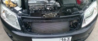
Installing PTF in a blind bumper
The most difficult and time-consuming option is to install fog lights in a solid bumper (i.e., one that does not have factory holes for this):
- Remove the bumper from the vehicle in accordance with the repair and operating instructions.
- Determine the optimal location for installing headlights in terms of housing shape and compliance with regulations.
- Make a hole for the headlights. The best way is to drill holes around the perimeter and saw through the gaps with a file. The hole must be adjusted to ensure proper fit between the body and the decorative frame. Small fragments of the bumper are carefully cut off with a construction or stationery knife.
- Drill holes for the fog lamp housing, which is secured with suitable bolts.
- Install the headlight into the housing and mount the protective cover. It clings to the plastic of the bumper.
- You can adjust the headlight using a special key included in the kit.
Installing PTF on the external bracket
Option for mounting foglights on a steel bracket:
- Mark the mounting points of the bracket on the bumper in accordance with the requirements for installing fog lights. As a rule, additional headlights are installed on the bracket.
- Screw the bracket to the bumper with self-tapping screws or bolts.
- Install the fog lights on the mounting points and connect the wiring.
Example of installing headlights on a bracket
Installation of PTF in standard openings
In order to install headlights in a bumper that has standard plugs, you must:
- Raise the front of the car by placing a wooden block 150-200 mm high under the wheels. For greater convenience, you can place the car on a lift.
- Remove the protective shields covering the lower part of the bumper.
- Unscrew the clips of the standard bumper plugs.
- Insert the fog lamp into the guides and secure with standard screws. When using non-original headlights, there may be discrepancies in dimensions and mounting points. In this case, you have to adjust the parts to each other. Below is a photo gallery of installing Chinese fog lights in the Hyundai Elantra HD bumper.
Wiring
When pulling and installing wiring, you must follow the following safety rules:
- disconnect the battery;
- the cross-section of the wire must correspond to the current carried;
- connection points must have reliable contact;
- Only wires of the same material can be connected (to reduce electrochemical corrosion);
- It is advisable to shed the twists with solder;
- the junctions of the wires are insulated with heat-shrinkable tubing or electrical tape;
- Avoid placing wiring connections in areas prone to flooding;
- to protect them from bending and chafing, it is recommended to protect them with a split corrugated tube;
- the wires are laid parallel to the standard harnesses and fixed to them with plastic ties;
- The power supply circuit for the fog lights must be protected by an individual fuse;
- When laying the wire, you should ensure that there are no hot or moving elements in the path, as well as sharp edges.
Neglecting the rules for safe installation of electrical wiring leads to overheating of the circuits and a fire, which can destroy the car.
Before starting installation, it is recommended to assemble the future electrical circuit and test the operation. This event allows you to find and eliminate errors made during development.
Wiring and headlight testing
Reworking the low beam button
As already mentioned, the button for turning on the low beam and the button for the dimensions of the VAZ 2114 are combined and arranged in pairs. Their main drawback, which most motorists point out, is the absence of a power indicator LED on the low beam button.
This is a rather serious problem, since it is often unclear whether the headlights are working or not (especially during daylight hours). You can fix this by changing the button yourself.
For this you will need:
- button to be changed;
- the second button is the same: donor;
- soldering iron or (better) soldering station.
The redesigned button follows the pattern shown here. Soldering the LED itself from board to board is highly not recommended, since this requires a soldering station equipped with a hair dryer, special flux and high qualifications in working with them.
First, we need to remove the main button from the car panel (how to do this has already been described above).
After it has been removed and disconnected from the wires, do the following:
- remove the keys by lifting the flathead screwdriver;
- disassemble the button housing by pressing the latches with a screwdriver (the buttons themselves should now be in the “on” position);
- we see that there are two diodes on the size button (backlight and indication), and on the low beam button there is only one backlight button;
- remove a couple of legs and a couple of contacts from the donor button;
- rearrange them into free spaces on the task button;
- remove the card from the donor button with two diodes and insert it into the working button instead of the card with one diode;
- solder the board to the added legs;
- make a hole in the button cover (this can be done with a sharp knife or simply drilled with a flat screwdriver).
The junction of the newly installed legs and the new board must be well soldered. Otherwise, the button may quickly fail or malfunction.
Having completed all these operations, all that remains is to assemble everything in the reverse order and install the updated button in its place (during installation, it is important that all the mini-latches on the case fall into place).
Fog lights, or simply PTF, are an important element of a car's lighting system. Unfortunately, not all manufacturers equip their cars with these devices. AvtoVAZ with its model 2114 is no exception. PTF for the fourteenth is available only for a fee and in the most expensive configuration.
Not everyone sees the point in buying a more complete version just to get PTF. An excellent solution is to install fog lights yourself.
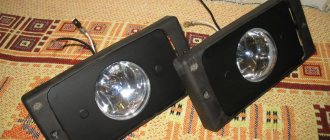
Beautiful and effective
Video
The wiring diagram for installing fog lights is shown in a video filmed for the “Car Lover” channel.
When installing fog lights via a relay, a car owner may experience some difficulties. It seems that everything is clear with the installation of the headlights themselves and the laying of the wires, but how to connect the relay and connect everything along with the fuses. To do this, it is advisable to have minimal knowledge in electrical engineering.
Preparing to connect the fog lamp relay
Tools required to connect the relay:
You will also need a large number of consumables, such as electrical tape, clamps, terminals, heat shrink, and corrugation. These materials will ensure the connection of the wires and their durability during use.
About wires
Now you need to deal with the fog lights themselves. As we know, there are only two wires coming from each headlight (“plus” and “minus”, respectively). We connect the latter to the body, that is, it will be our mass. Next, we lift it onto the relay so that the wires are not visible, and connect it to the battery.
This completes the connection of the fog lights via the relay. The connection diagram, as we see, is very simple, so even a novice motorist can cope with this task.
Connection diagram for fog lights via relay
Before starting installation, you need to decide on the connection diagram:
Autonomous, the fog lights will turn on independently, although then the headlights can drain the battery completely, which is fraught with problems. Connection occurs to the positive dimensions or ignition wire +ACC
Watch the video below to see how to properly connect the relay.
With the ignition, in this case, the fog lights cannot be turned on without the engine running, usually the plus from the ignition switch or IGN2 is used, which is best looked for using a voltmeter, since if you use a lamp probe, there is a possibility of damage to the car's electronics.