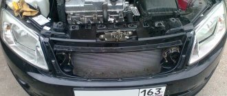
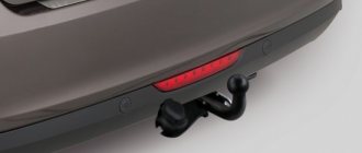
I installed a signal from a Volga car a month ago, without installing a mesh in the bumper (my readers will understand). I haven’t written before, because I’ve only now completed everything (regularly) according to my mind. I connected the signals through a relay and a 15A fuse, I know there is a sect of relayless installation, but I’m not a member of it. I won’t describe how I removed the bumper this time, for anyone who hasn’t removed it yet, I will say that there is nothing complicated about it, the main thing is to be careful and with an assistant (preferably). The signals themselves were installed on brackets made of titanium (whatever came to hand was stainless) 2 mm thick. First I cut out paper templates using a marker
I traced them on metal and with the help of a grinder and such and such a mother made them. The brackets were attached with M8x30 screws to the bumper under the bumper (I removed the standard screws). We attach the sigals to the brackets with a nut and a lock washer (included) - all the mechanical parts are done, let's move on to the electrics. We cut off the standard signal and unscrew it, solder a sealed two-pin connector onto the cut wires,
we isolate it and hide it in a corrugation (Chinese connector from Aliexpress, also sold in auto stores). We make a harness from corrugated wires.
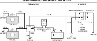
The principle is simple (I won’t draw a diagram, but if necessary, write), we use the wires that the manufacturer intended for the signal as controls for a four-pin relay. From the positive screw (in the electrical distribution box, under the hood on the driver's side), we pull the wire to the fuse, from the fuse to the power contact of the relay, and we connect the output from the relay to signals (from the positive screw to the relay and then the signals, a stranded wire with a cross-section of 1.5 was used). The peculiarity of the electrical wiring is that it is placed in an electrical distribution box
located under the hood on the driver's side, the fuse and relay are installed in their “standard” places.
To take the positive from the screw, use an 8 mm ring terminal,
(you need 6 mm, but the area for the terminal is very large and at 6 mm, the crimp of the terminal would fall under the clamping nut - there are elongated ring terminals, I looked for it and couldn’t find it). For fuse and relay contacts I used 4.8 mm Lyra contacts, they
They are standard and installed in blocks (I ordered terminal 505 in the online store). I crimped the terminals with a crimper purchased in China on aliexpress, profile SN-48B,
squeezes quite well. I used the empty sockets of the standard pads for the relay and fuse (they were just empty, I don’t know how you have them, comfort MM equipment). Now the only difference from the factory version of the electrics is the VAZ relay (Vesta has its own imported ones). I inserted the bus into the electrical distribution box from the headlight side, there is
a place for the wiring entry, covered with a plug. The contacts on the signals themselves are ordinary father - mother, I used two mothers. I don’t honk often myself, but I’ve already had to “honk” the horn a couple of times – quite decently.
Price tag: 1,000 ₽ Mileage: 6500 km
Recommendations
Comments 39
The lyres fit into the mounting sockets under the contacts - in the empty spaces where you want to install a relay or fuse. I'll draw a diagram later.
The relay has 4 contacts, divided into two pairs. The first pair is “low-current” - for closing and opening the relay. We connect the two wires that went to the signal (pins 85 and 86) in any order. The second pair is power, which will supply current to the signals. The wire from the ring terminal (with +) goes to the fuse contact (4.8 pin is inserted), from the fuse (4.8 pin is inserted) to the relay (4.8 pin is inserted) - any contact for relay 30 or 87, and from the remaining contact to the signal. The principle is that the wires are connected in pairs, two from the previous signal control the relay (85 and 86 on the relay). And the power wire from + to the fuse, from the fuse to the relay (let's say 30), and from the remaining (let's say 87) contact to the signal.
From the signal relay - wires to the relay control, plus from the red screw contact (on the right). The main principle.
I just don’t understand how the standard signal works without an additional relay and fuse? And why can’t you connect the Volgov signal to the standard translation and that’s it? The standard wire already has a plus. Why put a separate plus in the fuse box? Why do we need dances with a tambourine, relays, fuses, additional wiring, etc.?
You can connect it to the standard one, just replace the fuse. But the Volgo signal is controlled by one plus, and the minus is taken from the body, and there are two Volgo signals, when the standard one is one. Since it’s a hell of a hassle with the wiring for two signals, the decision was to make it as standard, and the cross-section of the wire for the Volga signals needs to be thicker, otherwise the sound might not be as bassy. For myself, I decided not to check the car’s electrical system to see if it will hold up or not, but to make sure it works.
OBD 2 pinout
Brands and years:
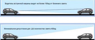
Gasoline passenger cars and light commercial vehicles manufactured or imported into the United States since 1996 (US CARB and EPA legislation) and in Europe (EOBD) since 2000-2001 (European Union Directive 98/69EG) and Asia (mainly since 1998). ).
Conclusions and their purpose:
| № | Color | Purpose |
| 2 | J1850 Bus + | |
| 4 | Body grounding | |
| 5 | Signal Ground | |
| 6 | Line CAN-High, J-2284 | |
| 7 | K-line diagnostics (ISO 9141-2 and ISO/DIS 14230-4) | |
| 10 | J1850 Bus- | |
| 14 | Line CAN-Low, J-2284 | |
| 15 | L-line diagnostics (ISO 9141-2 and ISO/DIS 14230-4) | |
| 16 | Power supply +12V from battery |
Diagnostic connector pins for used protocols
Pins 4, 5, 7, 15, 16 - ISO 9141-2.
Pins 2, 4, 5, 10, 16 - J1850 PWM.
Pins 2, 4, 5, 16 (without 10) - J1850 VPW.
The ISO 9141-2 protocol is identified by the presence of pin 7 and the absence of pins 2 and/or 10 on the diagnostic connector.
If pin 7 is missing, the system uses the SAE J1850 VPW (Variable Pulse Width Modulation) or SAE J1850 PWM (Pulse Width Modulation) protocol.
All three data exchange protocols operate via a standard OBD-II J1962 connector cable.
Standard signal - article number and price
The sound device of the Lada Vesta is sold under article number 820110. The kit includes three parts:
- two low-tone sound devices with article number 2110372102013,
- hex bolt for assembly - 7703602226
- nut - article number 7703033206.
The contents of the package allow you to install the horn immediately and do not require additional purchases. The average cost of Lada Vesta Cross snails is 450 rubles. They operate with a voltage of 12V. The standard horn is made of ABS plastic.
Methods for diagnosing ECUs and errors on Lada Vesta via OBD2
Let's look at examples of analyzing machine systems in different ways.
Check Engine light on Vesta?
Detailed article on the causes of Check Engine and how to clear the Check. If your Check Engine light comes on, read this article immediately. The material explains what a Check Engine is, what to do if it appears, and how to remove this error yourself.
Is the Check Engine light on?
TOP 15 reasons why the Check Engine light comes on and ways to solve the problem. Read the article to solve the Check Engine problem.
To enter the BC diagnostic mode, hold down the top key and turn on the ignition.
Reviews of diagnostic scanners for LADA VESTA
Read detailed articles on the review of car scanners, including those compatible with LADA VESTA.
Reviews of OBD2 diagnostic car scanners
This section provides descriptions of diagnostic scanners and adapters. Before purchasing a scanner for your car, it is recommended that you read reviews of the most popular equipment models.
New software is written using programmers. There are open and closed ECUs.
- In a diagnostic way. Without removing the ECU from the vehicle via the diagnostic connector using flash loaders and a program such as Combiloader.
- Work via BSL mode of the ECU processor. With this method, programming the ECU is carried out by removing the latter from the car using bootloaders that work with the ECU processor via BSL mode.
Basic signal malfunctions of the Lada Vesta car
On Vesta’s car the signal does not work due to the following three main faults. This could be due to wiring or vibration:
- A broken sound signal on Vesta is not good. Russian traffic regulations prohibit using a car with a faulty horn. The main symptoms of a part failure are: complete absence of sound and its activation without driver participation. The reason why the horn does not work may be high voltage.
- Vesta snails operate with 12V power. When an oxide film forms on the contacts, the wires can instantly burn out. This type of horn cannot be repaired. To protect it from damage, regularly lubricate the contacts with specialized products. Make sure that the composition contains mineral oils, thickeners and stabilizers. Products based on graphite and finely ground copper powder have good electrical conductivity.
- Vibration from the motor quickly wears out Vesta's sound device. The fuse is the first to suffer. If it burns out, the signal will stop working. Checking the fuse will show whether it is to blame for the problem or whether the electrical circuit has burned out. Both parts can be replaced. Before doing this, find the reason for their combustion so that the replacement does not wear out prematurely.
Fuse box Lada Vesta in the engine compartment
Access to this block is even easier - just open the hood and open the block next to the battery.
Let us remind you that the maximum current on the fuse is determined according to the table below. The fuse number is indicated on the body of the mounting block, and the amperage of the fuse is indicated on its left side.
If, after replacing a failed fuse, it melts again, you must contact your dealer to eliminate the cause of the high current.
The Lada Vesta has two beeps. One signal is a warning signal, and the other is an alarm signal.
To replace or repair signals, you need to prepare the car for work.
Raise the hood and disconnect the negative terminal from the battery using a 10mm wrench.
In order to remove the signal signal, you need to remove the bumper, as described in the article “Removing and installing bumpers on a Lada Vesta car.”
After this, disconnect block 1, Figure 1, of the front wiring harness from sound signal device 2.
Using a 13mm socket, unscrew nut 3 securing the sound warning device to the car body and remove the sound warning device.
Install the sound signal device in the reverse order of removal.
The tightening torque of nut 3, Figure 1, fastening the sound signal device is 20…30 Nm (2…3 kgf.m).
After repairing or replacing the signal, we install the front bumper.
Manufacturers and prices of analogues
- The 12V pneumatic signal LADA D-90 is suitable for replacing the standard horn. The sound frequencies of this part are higher: from 410 to 510 Hz. Heat-resistant plastic increases the life of the device. Such models are more difficult to install. Before purchasing, make sure that the horn will fit and will not interfere with other parts. The size of the sound signal is 90 millimeters. Its average cost is 800 rubles. Product code - 00044123.
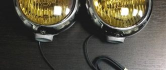
- Most often, Lada Vesta owners choose a Volga device to replace the horn. It sounds louder and operates at the same power - 12V. The standard horn sounds high. Such a horn is hard to hear, so the likelihood of getting into an accident increases. The Volga part sounds more solid. It can be clearly heard by passers-by and drivers of other cars. Standard Snails SKYWAY 004 produce sound with a frequency from 390 to 460 Hz. It is sold with article number S07601004 and costs an average of 650 rubles. The kit includes installation instructions.
- You can consider the Volga signals from Avtokom. They sound noticeably lower than the original horns: 105-118 dB. Vesta's native horn operates at 3A power. The Autocom model consumes 7A current, so it is not recommended to connect it to the basic wiring of the car. The Vesta part may not work stably. You will need to install an additional four-pin relay and another fuse. The cost of Avtokom is about 900 rubles. Product code - S302D303D.
- Sound signal Hella DL 50 - the original costs from 2100 rubles. It is also suitable for replacing the original part. Operates at 12 V power. 380 Hz frequency provides clear and loud sound.
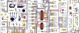
Full schematic diagram of Lada Vesta
Scheme norm and standard
Luxury scheme
The original image weighs 6 MB, you need to right-click on the links and click “open in new tab”: (
And
).
Digital designation of elements of the electrical circuit diagram of Lada Vesta Lux cars
1-Generator 2-Battery 3-Starter VAZ-2180 4-Rear outer left light 5-Left rear headlight 6-Right fog light 7-Rear window heating relay 8-right right headlight 9-Inner left rear light/Left Rear Inside Light/ 10-Rear External Right Light/Right Rear Outside Light/ 11-License Plate Light/12-Licence Plate Light/ 13-Trunk Lighting/14-Fuse/ Fuse F29 10A/ 15-Fuse/Fuse F70 60A/ 16-Relay/Relay K1/Unloader K15 R 17-Ignition Switch/ 18-Fuse/Fuse F71 60A/ 19-Fuse/Fuse F72 60A/ 20-Fuse/ Fuse F1 15A/ 21-Fuse/Fuse F73 10A/K30 Sound signal 22-Fuse/Fuse F2 25A/K15R Left steering column switch 23-Right Rear Inside Light/24-Additional Stop Light/ 25 -Left Fog Light/Left Front Foglight/ 26-Hazard Switch/Emergency Light Switch/ 27-Fuse/Fuse F4 20A/K30 Left Steering Wheel Paddle Switch 28-Fuse/Fuse F74 5A/Reverse Switch 29-Fuse/Fuse F41 20A/ ACC Additional Consumers 30-Fuse/Fuse F20 5A/Outside Mirror Heaters 31-Reverse Light Switch/ 32-Left Steering Light Switch/Warning Light Combi-Switchs/ 33-Right Steering Light Switch/Wiper-Washer Combi-Switchs/ 34-Fuse FA/K30 Windshield Defroster 35-Rear Screen Defroster/ 36-Switch Block/Fascia Switch Unit/ 37-Left Rear Speaker/ 38-Right Front Speaker/ 39-Left Seat Heater/ 40-Right Seat Heater/ 41-Seat Heater Control Unit/ 42-Rear Fog Light/43-Left Rear Speaker / 44-Relay/Relay K21/Windscreen defroster 1 45-Fuse/Fuse F37 7.5A/Brake light right 46-Windscreen defroster/WindScreen Defroster/ 47-Glovebox light/48-Cover light switch glovebox/Glovebox Light Switch/ 49-Headlight Adjuster Switch Unit/ 50-Immobilizer Antenna/Immobilizer Ring/ 51-Controller/ECU BCM M0/B-Pf-T4-L3/ 52-Controller/ECU EMM B -Pf-T4-L4/ 53-Fuse/Fuse F5 15A/K15R seats 54-Fuse/Fuse F47 25A/K30 EMM 55-Fuse/Fuse F48 30A/K30 EMM 56-Fuse/Fuse F8 5A/ZPTO 57-Rear loudspeaker right// 58-Fuse/Fuse F61 30A/Rear window heater 59-Left Door Sill Light/60-Right Door Sill Light/61-Relay Lada Vesta/Relay K8 ACC/ 62- Trunk Lock Actuator Switch/ 63-Fuse F32 10A/K15 engine compartment 64-Front Windowlift Actuator Relay/ 65-Left Front Door Lock Actuator/66-Left Front Power Window/ Driver Windowlift Actuator/ 67-Power rear left window/Left Rear Windowlift Actuator/ 68-Power front right/Passenger Windowlift Actuator/ 69-Front right door lock actuator/Passenger Doorlock Actuator/70-Rear left door lock actuator/Left Rear Doorlock Actuator/ 71-Right Rear Doorlock Actuator/ 72-Right Rear Windowlift Actuator/ 73-Relay/Relay K6/Rear Window Lifters 74-Alarm Hood Switch/ 75-Left Front Door Switch/ Alarm Left Front Door Switch/ 76-Alarm Right Front Door Switch/ 77-Alarm Left Rear Door Switch/ 78-Alarm Right Rear Door Switch/ 79-Wind Wiper Motor glass/Windscreen Wiper Motor/ 80-Electric washer motor/Windscreen Washer Motor/ 81-Fuse/Fuse F27 5A/Parking sensors 82-Relay/Relay K25/Sound alarm 83-Alarm sound signal/Alarm Loudspeaker/ 84-Fuse/Fuse F18 3A/ Side turn signal left 85-Trunk Lock Actuator/86-Driver Door Control Switch Unit/87-Left External Mirror Unit/88-Right External Mirror Unit/ 89-Front Passenger Power Window Switch 90-Left Rear Door Control Switch Unit/ 91-Right Rear Door Control Switch Unit/ 92-Passenger Airbag Inhibitor/ 93 -Sound Horn/ 94-Relay/Relay K24/Horn 95-Ignition Coil Unit 2*2/Ignition Coil Unit 2*2/ 96-Driver Airbag/97-Rotating Joint/ 98 -Driver Seat Belt Sensor/ 99-Passenger Seat Belt Sensor/ 100-Driver Retractor/ 101-Passenger Retractor/ 102-Passenger Airbag/ 103-Driver Side Impact Sensor/ 104-Passenger Side Impact Sensor/ 105-Passenger Present Sensor/ 106-Fuse/Fuse F38 7.5A/Left Brake Light 107- SNBP control unit/Airbag Control Unit/ 108-Driver Side Airbag/ 109-Passenger Side Airbag/ 110-Relay/Relay K28/A/C compressor clutch 111-A/C compressor clutch/ clutch/ 112-Instrument Cluster Unit/113-Outside Air Temperature Sensor/ 114-Rain and Light Sensor/Rain Sensor/ 115-Brake Fluid Level Sensor/ 116-Indicator Lamp Switch Handbrake/Hand Brake Switch/ 117-Interior Air Temperature Sensor/Inside Air Temperature Sensor/ 118-Coolant Pressure Sensor/Freon Pressure Sensor/ 119-Fuse/Fuse F35 5A/Exterior Mirror Drive 120-Relay/Relay K23/Starter 121- Relay/Relay K7/Fuel Pump 122-Electric fuel pump module/Fuel Pump/ 123-Relay/Relay K27/Main ECM 124-Ignition Coil 1 cylinder/Ignition Coil 1 cylinder/ 125-Ignition Coil 2 cylinder/Ignition Coil 2 cylinder/ 126- Ignition Coil 3 cylinder/ 127-Ignition Coil 4 cylinder/ 128-Injector 1 cylinder/Fuel injector 1 cylinder/ 129-Injector 2 cylinder/130-Injector 3 cylinder/ Fuel injector 3 cylinder/ 131-4 cylinder nozzle/Fuel injector 4 cylinder/ 132-Electric radiator fan/Motor Fan/ 133-Motor Fan Relay Unit/134-Brake Pedal Switch/ 135-Module Throttle Actuator/Trottle Body Unit/ 136-Fuse/Fuse F39 10A/DRL 137-Timing Valve/VVT Valve/ 138-Fuse/Fuse F15 5A/Headlight Adjustment Switch 139-Intake Air Temperature Sensor/MAT Sensor/ 140 -Intake air pressure and temperature sensor/MAP&T Sensor/ 141-AMT Controller/Automatic Transmission Control Unit/ 142-Oil Pressure Switch/143-ECM Controller M86/Engine Control Unit/ 144-Accelerator Pedal Sensor/Accelerator Pedal Position Sensor/ 145-Crankshaft Position Sensor/Crankshuft Position Sensor/ 146-Knock Sensor/Knock Sensor/ 147-Phase Sensor/Camshuft Position Sensor/ 148-Oxygen Sensor 1/Upstream O2 Sensor/ 149-Oxygen Sensor 2/Downstream O2 Sensor/ 150-Coolant Temperature Sensor/ 151-Canister Purge Valve/ 152-Fuse/Fuse F28 5A/L15 EURU 153-Intake Module Flap Control Valve/Intake Air Unit Valve/ 154-Gidronik Receiver 2// 155-Water pump Hydronic 2// 156-Fuel pump Hydronic 2// 157-Control unit Hydronic 2// 158-Relay Lada Vesta/Relay K29/Radiator fan 159-Heater assembly/HVAC Assembly/ 160-Controller SAUKU/HVAC Control Unit/ 161-Relay/Relay K1/Autostart CL 15a 162-Relay/Relay K26/Autostart CL 50A 163-Gear Shift Actuator/ 164-SAUKU control panel/HVAc Button Panel/ 165-Speed sensor AMT/ATCU Speed Sensor/ 166-Diagnostic connector/OBD2 Connector/ 167-Steering angle sensor/Steering Weel Angle Sensor/ 168-Lever shift actuator/Gear Shift Actuator/ 169-Relay/Relay K5/Heater electric fan 170-Cartridge for connecting additional consumers/Plug Connection Socket/ 171-Gear Select Actuator/ 172-Left Front Weel Speed Sensor/ 173-Right Front Weel Speed Sensor/ 174-Rear Left Speed Sensor wheels/Left Rear Weel Speed Sensor/ 175-Rear right wheel speed sensor/Right Rear Weel Speed Sensor/ 176-Hydraulic unit controller/ECU ESP 9.1/ 177-Fuse/Fuse F34 5A/VTR-DUPRK + Cruise control 178-Electromechanical amplifier steering wheel/Electric Power Steering Unit/ 179-Fuse/Fuse F77 30A/Remote start 180-Clutch Actuator/ 181-Combined Antenna/Combi-Antenna FM/GPS/GLONASS/ 182-// 183-Radio unit/Radio/ VAZ-2180 184-Terminal block “Era-Glonass”/Telecoms Unit “E-Call”/ 185-Lighting unit with interface “Era-Glonass”/Lamp with interfase E-Call/ 186-Fuse/Fuse F62 40A/K30 ESP 187-Fuse/Fuse F76 10A/K30 sound alarm 188-Fuse/Fuse F69 15A/ECM 189-Fuse/Fuse F21 15A/K15 SNPB 190-Fuse/Fuse F22 5A/K15 KP 191-Fuse/Fuse F23 5A/K30 KP 192-Rear View Camera/Revers Parking Assist Camera/ 193-Safe Parking System Unit/Parking Assist Unit/ 194A-Left Outside Ultrasonic Sensor/194B-Left Inside Ultrasonic Sensor/195A-Sensor parking right external/Right Outside Ultrasonic Sensor/ 195B-Parking sensor right internal/Right Inside Ultrasonic Sensor/ 196-Fuse/Fuse F51 5A/K30-power supply of relay windings 197-Fuse/Fuse F9 3A/K30-EMM 198-Fuse/Fuse F46 30A/K15R-windshield wiper 199-Fuse/Fuse F78 7.5A/ECM1 200-Fuse/Fuse F42 20A/K30 VSM 201-Fuse/Fuse F12 15A/K30 VSM 202-Fuse/Fuse F13 10A/K30 VSM 2 03-Fuse /Fuse F14 10A/K30-stop signal 204-Fuse/Fuse F17 5A/K15 delayed-backlight 205-Fuse/Fuse F16 5A/K15 delayed-brake switch 206-Fuse/Fuse F43 20A/K30 VSM 207-Fuse/Fuse F44 30A/K30 window regulators 211-Fuse/Fuse F30 5A/K15 EG 212-Fuse/Fuse F26 15A/Fuel pump 213-Fuse/Fuse F36 15A/K30 radio 214-Fuse/Fuse F60 70A/K30 EURU 215-Fuse/ Fuse F33 5A/K15 windings of the power window and heater relay 216-Fuse/Fuse F3 10A/DS left headlight 217-Fuse/Fuse F25 5A/VTR-ESP 218-Fuse/Fuse F65 25A/K30 ESP 219-Fuse/Fuse F31 5A/K30 EG 220-Fuse/Fuse F66 5A/K15 AMT 221-Fuse/Fuse F10 5A/selector AMT 222-Fuse/Fuse F68 70A/K30 AMT 223-Fuse/Fuse F11 10A/BS left headlight 224-Fuse/Fuse F19 10A/BS right headlight 225-Fuse/Fuse F68 15A/K30-PPG Gidronik 2 226-Fuse/Fuse F40 10A/DS right headlight 227-Fuse/Fuse F6 5A/starboard side 228-Fuse/Fuse F7 5A/left side side 229- Fuse/Fuse F9 3A/side turn signal 230-Clutch pedal position switch/Clutch Pedal Switch/ 231-Relay/Relay K22/Heated windshield 2 232-Fuse/Fuse F24 5A/ACC radio and EG 233-Fuse/Fuse F80 5A /K15R heated windshield relay 234-Fuse/Fuse F50 25A/K30 EMM 235-High-frequency loudspeaker right/Right Tweeter/ 236-High-frequency loudspeaker left/Left Tweeter/ 237-// 238-Engine harness connection connector H4mk/H4mk Harness Socket/ 239-USB+ Aux/USB socket/ 208-Fuse/Fuse F45 30A/K30 heater fan 209-Fuse/Fuse F79 40A/K30 engine fan 210-Fuse/Fuse F63 15A/Air conditioning compressor
Removal and installation - replacing the sound signal on Lada Vesta
- Changing the signal on the West is easy. For convenience, it is recommended to remove the bumper. This way it will not interfere with connecting the wires. It is better to remove the bumper with the radiator.
- Remove the numbers and air receiver. The bumper is attached to the body with bolts in tens, twenties and thirty from below (four self-tapping screws). The bumper is secured at the edges with 20 screws (next to the wheels). Unscrew the remaining screws on top while holding the lid.
- Place the part on the floor, first laying it with a soft cloth. Do not place the bumper on the ground: small pebbles can scratch the paint.
If the power of the new pipe on Vesta differs from the characteristics of the original one, before installation you need to equip the car with an additional fuse and relay. They will ensure stable operation of the new part. The minus wire in the standard version is connected to the steering horn button. Check this indicator before installing the pipes. In some models, the connection is made through a positive charge. Plus and minus are different colors. The positively charged wire is red with a white stripe.
It is not necessary to remove the standard Vesta horn. It can work together with the new one. This will increase energy consumption, so most car owners turn it off and leave it inactive in case the replacement breaks down. To connect it, it will be enough to connect the block.
Remove the negative terminal from the battery. Choose a location for new horns. They can be hung on old brackets from original Vesta parts. If the fasteners do not fit, buy new ones. It is better to inspect the fastenings before actual installation. Do not place the horn too close to the body. This will cause resonance: the wear of the part will increase, and the bell will be clearly audible in the cabin. Mark future holes for the brackets. Drill them. Screw the horns tightly. They should not dangle or shake when driving. Place the signal further from the bumper: moisture trapped in the membranes can short-circuit the contacts. If the installation is done correctly, you will not need to remove the bumper to remove the horns in the future.
Replacing the standard sound signal in case of breakdown
First you need to prepare the car for work by putting the parking brake on and turning off the ignition. Then you need to lift the hood and, armed with a “10” key, disconnect the negative terminal from the battery. Then you should dismantle the front bumper, which is best done with an assistant, so as not to damage the paintwork on the bumper itself and on the wings of Vesta.
The figure shows the mounting location of the Vesta signal, its plug and the signal itself.
Once this is completed, all that remains is to disconnect the plug with the wires from the signal horn. Then you can dismantle the signal itself, the bracket of which is attached to the body with one nut. For dismantling you will need an extension, a wrench and a 13mm socket.
Removing and installing the front bumper requires an assistant.
Assembly is carried out in the reverse order - you need to secure the signal, inspect its operation, install the bumper with an assistant and tighten the terminal on the Vesta battery.
How to connect the Volgovsky signal to Vesta
If you connect a signal from the Volga, it will differ from the standard wiring of a Lada Vesta car. Instructions are included with the horns. The diagram describes in detail the connection of wires. All charges are indicated by the symbols “+” and “-”.
- To replace the horn, install a fuse between the battery and the horn relay. The latter is better secured to the body. The parts should be located close so that the power wire does not have to be pulled too hard.
- Connect the wire to the pipes. Insulate them using corrugation.
- Secure everything with zip ties: wires that don’t “walk” under the hood will last longer.
- Remove the standard wiring by attaching it to the body: mortise clamps will do.
- Installing a Volga signal on a vesta takes the same amount of time as installing a standard snail signal. After connecting the wires, check the Volgov signal.
Common results of TO-1 "Lada Vesta"
We list the common problems of the Lada Vesta that appear within a mileage of 15 thousand km:
- scratches on glass - if their configuration is not typical of traces of standard equipment, then they are not subject to warranty replacement;
- play in the lower ball joints;
- knocking of rear stabilizer struts;
- creaking of rubber bushings of stabilizers;
- chafing of the cooling system pipes both under the hood and in the cabin.
- corrosion and burnout of the resonator body;
- not working heated windshield;
- Corrosion of turn signal contacts in side mirrors.
- malfunctions in the multimedia system.
Having familiarized yourself with this list, it is advisable to “try on” these problems for your car before passing TO-1 and, if the assumption is confirmed, draw the attention of the service center workers to them, without relying on identifying faults without the participation of the car owner.
Pneumatic signal
Initially, an electromagnetic horn is installed in the car. Such pipes consist of an electromagnet, a membrane and a core. The sound occurs when the core rod presses on the membrane. This type of horn is most often chosen by manufacturers: they have a simple design. They are divided into:
- Horns. Average sound quality. Outwardly they resemble a forge.
- Snails. Installed with the pipe facing forward. The design is not comfortable for installation; it is used in the production of Lada Vesta cars.
- Disks. Occupies minimal space. Easy to install.
- Pneumatic horns are louder than electromagnetic ones. Their volume reaches one hundred twenty-five decibels. The tonality of the pipe covers more frequencies. In order for the pneumatic signal to work stably, you will need a powerful compressor.
- Klaxons can consist of a large number of horns: up to five pieces. A programmable relay provides detailed melody customization. The resulting tone will be unique in its content.
- The music relay is used for entertainment vehicles only. Installing such a horn for driving around the city is prohibited by Russian law.
All cars have a device for producing sound signals (horn), but its sound does not always suit the owner. This is the main reason for replacing the standard horn with alternative options (for example, with a sound signal from the Volga). Let's look at this improvement in detail.
Nowadays, horns are usually used in pairs. One with a high tone, the other with a low tone. This provides strength and beauty of sound.
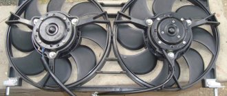
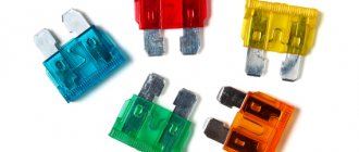
Will need to buy:
- A couple of sound signals from GAZ 3110 (article number for high tone - 22.3721, for low tone - 221.3721), approximate price 500 rubles;
- 4-pin relay 75.3777-10;
- Relay socket;
- Mounted fuse 10-15A;
- Single-core wire;
- Corrugation for wires;
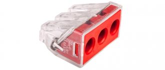
- Terminals;
- Brackets/brackets for mounting sound signals (optional).
Installation and connection of a sound signal from the Volga is shown using the example of the Lada Vesta sedan. On other cars (for example, Lada Largus, Granta, Kalina, Priora, Niva 2121 or XRAY) all actions are performed in a similar way.
Alternative options
In this case, the possibilities are limited solely by the imagination of the Vesta owner. Most often, sound signals from the Volga are installed on the Lada, since their sound is much louder. But there are other ways. The most common options for such “modernization” are:
- installation of signals from the Volga - in this case, different installation methods are possible (with connecting a relay in the cabin or under the hood)
- combined option;
— installation of other signals;
— installation of a signal with an integrated compressor;
— a combination of signal and high beam.
Setting other signals is just one of many options.
Installation of signals from Volga
It involves not only installing “shells” directly on Vesta, but also various options for connecting them. It is worth remembering that the sound signal from the Volga can be either old or new. However, they have no differences, except for a slight difference in tonality:
— sound signals Volga-3110 (22.3721/221.3721) – low and high tone;
- sound signals Volga, RAF S302/303D - low and high tone.
Sound pressure – 105-118 dB.
The signal from the Volga is perfect for the Lada Vesta.
It is necessary to take into account that simply replacing the signals on Vesta will not work, because their current consumption is different. For Vesta this figure is 5A (passport data), although in reality it usually does not exceed 3.5A. Signals from the Volga consume 8A each, which gives a total of 16A. Therefore, for their installation it is necessary to use a 4-pin type relay. In particular, you can use relay 904.3747-10.
In addition, on Vesta, only one plug is supplied to the factory signal - “Plus” is permanent, since it supplies power to the fan, and “Minus” comes from the button on the steering wheel. Regarding the Volga signals, they only need “Plus”, because “Minus” goes directly through the metal mount to the body.
This mounting option will lead to vibration and ringing during signal operation. Brackets must be used.
It is also necessary to take into account the dimensions of the sound signals - the Volgov ones are larger than the standard ones on Vesta. Therefore, installation in factory locations is excluded. In addition, it is not advisable to mount them directly to the body, as this will lead to vibration, and the sound of resonating metal will be mixed with the horn. So the best solution would be to use a bracket. The advantage of this option is its low cost - a set of “Volgov” signals will cost about 1,000 rubles.
Installation of relays in the interior of Lada Vesta
This is done directly in the fuse box. To carry out the work you will need the following components:
— sound signals from the Volga;
— 4-pin type relay;
— relay block;
- single-core wire;
— terminals – wide (6 units) and narrow (1 unit).
For installation, it is best to use the free space in the fuse box, to which the wires from the contact relay, which is responsible for activating the signal on the steering wheel, are transferred. In the place that has become vacant, a wire from relay contact “87” is placed. Next, you will need to remove the wire from the 13th contact block and insert it into the 13th connector “87” of the relay contact.
Connection diagram for Volga signals on Lada Vesta.
To supply “Plus”, you will need to feed the wire to relay contact “30” from connector “Ш5-6”, using a jumper of contact “86”. In this case, you will have to insulate the wire in red-white or black-white color, since “Plus” always goes to it.
Signal relay from the Volga to the fuse box of the Lada Vesta.
This method has a number of advantages:
— location of wiring under the hood;
— installation of the relay in the appropriate block, which guarantees dryness;
— use of a separate “Plus”.
However, if you have a complete lack of experience and knowledge in the field of car electrics, it is better to contact an auto electrician when installing a relay in the cabin.
How to install a Volga signal
Remove the front bumper (instructions for XRAY, Vesta, Grant, Priora, Kalina, Largus). If it was decided not to remove the standard sound signal (if necessary, you can return to the initial version), then we are looking for a suitable place to install signals from the Volga. Most often they are placed on the front bumper amplifier (on standard mounting bolts), behind the radiator grille or under the headlights on brackets.
Problems when paying with bank cards
Sometimes difficulties may arise when paying with Visa/MasterCard bank cards. The most common of them:
- There is a restriction on the card for paying for online purchases
- A plastic card is not intended for making payments online.
- The plastic card is not activated for making payments online.
- There are not enough funds on the plastic card.
In order to solve these problems, you need to call or write to the technical support of the bank where you are served. Bank specialists will help you resolve them and make payments.
That's basically it. The entire process of paying for a book in PDF format on car repair on our website takes 1-2 minutes.
If you still have any questions, you can ask them using the feedback form, or write us an email at
How to connect the Volga signal
Standard sound signals of LADA cars consume no more than 5A, and Volga horns consume 7A each. In this regard, to connect them it is necessary to use a 4-pin relay. The Volga signal connection diagram is universal for all cars:
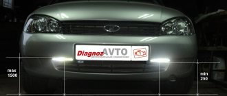
Before starting work, it is recommended to disconnect the negative terminal from the battery. All wires are laid in corrugation. We place the relay in a place protected from moisture and dirt. The whole process is also shown in the video:
About the guarantee. If you independently modify the car in terms of electrical components, there is a possibility of refusing warranty service for the car. Therefore, the installation of signals from Volga should be carried out at a service center, where after connection they will be ready to provide a document confirming the quality of work. You can also contact an authorized dealer for such modifications.
Are you satisfied with the operation of the standard sound signal on the LADA model? Are you ready to install a Volga horn? Let us remind you that we previously looked at other methods that can make operating a car more comfortable. For example, installing a gas tank cap bracket or how to make a flip-flop ignition key.
Additional functions
The display also displays other parameters of the Lada Vesta, which greatly facilitate driving not only for beginners, but also for experienced drivers. For example, data from parking sensors ensures easy parking of a car by generating light and sound signals. On-board computers are provided on the entire Lada vesta sw cross line, station wagons and other luxury models. The operation of standard electronic devices is ideally complemented by additional equipment; its installation is carried out at service stations or with your own hands. For example, the standard cruise control of the Lada Vesta successfully interacts with the additional onboard onboarder. Modern onboarder models have advanced functions: they are integrated with a satellite navigation system, equipped with an Internet connection and TV.