Today, all modern cars without exception are equipped with hazard warning lights (HAS). Its purpose is to warn other motorists about a vehicle malfunction, thus marking it on the road. In what cases is the emergency alarm button used and how this system works - read below.
How to remove the hazard warning button on a viburnum
Lada Kalina 2.
REPLACING INSTRUMENT PANEL SWITCHES
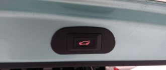
To remove the tailgate lock switch, do the following.
1. Disconnect the wire from the negative terminal of the battery.
5. Install the removed parts in the reverse order of removal.
To remove the hazard warning switch
do the following.
You will need a Phillips blade screwdriver.
1. Disconnect the wire from the negative terminal of the battery. 2. Remove the heating (air conditioning) and interior ventilation control unit (see “Removing and installing the unit
5. Press the lock of the hazard warning switch (for clarity, shown by an arrow on the removed switch) and remove the switch from the socket in the central trim of the instrument panel.
6. Install the removed parts in the reverse order of removal.
As everyone probably knows, there is a shortage of places for buttons on the Kalina. I have all the places to take. So there is an unused place where you can “shove” buttons. I didn’t want to buy ready-made ones, and the price for them is from 150-200 rubles. per piece somehow didn’t attract me.
But you need buttons. I bought two buttons for fog lights on a viburnum at the market for 70 rubles. PC. and connectors for them 30 rub. PC.
I arrived home and removed the center console to get everything aligned. And away we go. I brought everything home, removed the plugs that are near the emergency lights. I thought for a long time about how to redo it, I saw many ways, but unfortunately for a long time I could not find it and did not find it. And I decided to act in my own way, instinctively. I figured out how to roughly cut it, found this information, about 4 mm each, I got more (.
Next, I cut out the insides, with the expectation that the plug would fit onto the button with a slight tension.
Next, from the cover of the fog lamp button, I cut out the middle that will be fixed to the button. I tried everything on in place and adjusted it a little.
And then it's time for hot glue. I inserted the buttons into the seats. He heated the glue and glued the plug onto the button, aligning it until it hardened.
Oh yes, I cut the plastic with a utility knife, and where I couldn’t get into it with a knife, I removed the excess with a soldering iron. Now, when not working (the button is pressed), the buttons are flush with the emergency button, and when pressed, they are flush with the panel. I like. A little later there will be pictures in the car.
In order to remove the center console (the black trim on the instrument panel) of the Lada Kalina, we will need a Phillips screwdriver and a lot of patience, especially when installing it later, so we will have to be patient.
- The first step is to remove the cassette player, if you have one installed, and disconnect the wires connected to it.
- It is also better to remove the metal insert in which the radio is mounted to make removal easier. After it has been removed, we press on the back side of the plugs, which are located on both sides of the “Hazard Alarm” button.
- And unscrew the two bolts securing the lower part of this lining, which are located under these plugs with a Phillips screwdriver:
- Then you need to remove the three heater adjustment levers, which are marked below in the photo with numbers 1, 2,3. They are easy to remove; just pull them with a little effort.
- Now, disconnect the plug from the hazard warning button:
- After this, you need to slightly pull the lining towards you, starting from the very bottom, overcoming the obstacle of the metal clamps, and pull the lining out of its seat.
- To remove it completely, you need to disconnect all the wires that lead to the lighting bulbs and fan speed control:
After this, it can be easily removed without any problems. But you will have to tinker with the installation of this overlay, well, at least I tinkered for probably 20 minutes until I got everything in place.
How to activate the VALET service mode
p, blockquote 13,0,0,0,0 —>
Activation is possible in two ways: using a secret button and using a key fob. To activate the button, you must perform the following sequence of actions:
p, blockquote 14,0,0,0,0 —>
open the car using the key (if the central locking does not work);
turn on and then turn off the ignition;
press the secret button for a certain time (usually more than 2 seconds);
an audio message from the siren, blinking of the indicator LED or blinking of the emergency or low beams confirm the activation of the service mode.
If the key is lost, the service mode can be activated within a short time after the doors are mechanically opened. In this case, the sequence of actions is:
p, blockquote 15,1,0,0,0 —>
with the help of special services or independently using generally accepted methods, open the car door;
immediately press the secret button (for some alarm models the number of presses may differ; it is better to familiarize yourself with the sequence of actions in an emergency situation in advance);
If the car continues to give an alarm signal of the siren, or the hidden button is not found, you should remove the battery terminal, find the VALET button, then reconnect the battery, immediately press the button.
Enabling the VALET mode using the key fob is carried out in the following sequence:
p, blockquote 16,0,0,0,0 —>
turn the ignition on and off;
wait more than 10 seconds;
simultaneously press two key fob buttons and hold them for a certain time.
For different models of car alarms and key fobs, the combination of buttons may be special. In many cases these are buttons 1 and 2, open and close, open and siren, and others.
p, blockquote 17,0,0,0,0 —>
Some car alarm models do not have the ability to enter service mode from the key fob.
p, blockquote 18,0,0,0,0 —>
If the service mode is turned on, the driver is notified about this by an audible signal or a two-way alarm key fob when turning the ignition on and off and starting the engine.
p, blockquote 19,0,0,0,0 —>
What to do if the turn signals and emergency lights on a VAZ-2110 do not work
Domestic VAZ 2110 model cars are deservedly considered trouble-free. Nevertheless, even in them, certain minor breakdowns sometimes occur. For example, the emergency lights and turn signals often stop working, less often - only one thing. The lights either do not light up at all or, on the contrary, do not turn off. Experienced owners of "ten", as a rule, know very well what to do in such situations, but novice drivers often do not know how to solve the problem. Let's close this gap and figure out what to do if not a single turn signal is functioning and the emergency lights have failed.
Turn signals and emergency lights in combination on a VAZ-2110
Diagram of turn signals VAZ-2110.
When operating a car, its owner may encounter various system malfunctions, including failure of turn signals to work. They may either not turn on or not turn off. There are different reasons.
Verification algorithm
The driver needs to check
- All lamps.
If one lamp does not work, check it and the wires suitable for it.
In rear turn signals, the printed tape and connector often “moody”.
- Fuse F16 or F19.
- Relay.
- Mass on turn signals.
- Understeering's shifter.
The steering column switch is checked by checking the contacts.
- Wiring.
Pinout of the light control module Lada Kalina and Lada Priora
| Contact | Contact assignment |
| 1 | indicator lamp for turning on the rear fog lights |
| 2 | to the rear fog lamp relay |
| 3 | indicator lamp for turning on the front fog lights |
| 4 | to the front fog light relay |
| 58 | power output for side lights |
| 30 | constant power supply “+12 Volts” |
| G | to the gearmotor of the electric headlight corrector |
| 56b | To the gear motor for adjusting headlights |
| 58b | to the illumination of the instrument panel and interior controls |
| 31 | minus "-" |
| Xz | “+12 Volt” power supply from the ignition switch |
| 56 | to the headlights |
Features of the scheme
The electrical circuit of the VAZ-2110 turn signals includes:
The last two elements, responsible for the turn signal, are located nearby - in the mounting block. This unit is installed in the cabin, to the left of the steering wheel. It is closed by a decorative flap, to access which you just need to press the latch located above.
The emergency lights operate in parallel with the turn signals. Their wires are connected by the terminals of one block. It is from this that the veins go to the button that switches the general lighting devices to a mode signaling a breakdown that has occurred on the road. You need to know about this feature of the circuit when starting to search for the reasons for the failure of the lights. The problem is that a faulty VAZ-2110 emergency warning button often causes the turn signals to fail.
Installing a service alarm button
When choosing a location to install the button, consider the following conditions:
- Concealment - it should not be obvious during a quick inspection of the external panels and typical installation locations. If it is relatively easy to access the mounting block on your machine, then you should not stick the button on its outer side - it is better to fasten it on the back side. But secure it so that it can be felt.
- No nearby heating or moving elements. You should not glue the button onto the body of the stove or near its pipes, as the double-sided tape will come off. On pedals, you can accidentally hit it with your foot and tear it off or break it.
- The presence of other wiring harnesses nearby: when installing an alarm system, you need to pass a maximum of the wiring harnesses through the standard ones, which makes it difficult to find the central unit.
- Length reserve: if you glue the button inside the steering column casing behind the cutout of the height adjustment lever, then make sure that in all positions of the column the wire is not stretched, bent or pinched.
You can find out how to install a car alarm by reading the complete installation instructions for Starline A93.
/ Scheme for emergency gang VAZ 2110.md
Emergency gang diagram for VAZ 2110
Diagram for switching on direction indicators and hazard warning lights for VAZ-2107 Diagram for turning indicators and hazard warning lights on VAZ-2109, VAZ-2108 and VAZ-21099 Direction indicators for VAZ 2110, VAZ 2111, VAZ 2112, Lada Ten
The main fuses and relays on a VAZ car, , , are located on the left side of the steering wheel, just below. The figure shows the symbols on the fuse mounting block. F1-F20 - fuses - almost all car circuits are protected by fuses designed for different rated currents. Exceptions are the following circuits: To locate a faulty fuse, use the table of circuits protected by fuses. Before this, it is necessary to find the cause of the blown fuse, eliminate it, and only then install a new fuse. The table shows the circuits that each fuse protects, but on each model some of them may be missing due to the absence of certain devices - power windows, lock drives, etc. It is prohibited to replace fuses with jumpers. This can lead to failure of various devices. Most fuses and auxiliary relays are located in a separate mounting block (Fig. Location of relays and fuses in a mounting block built into the instrument panel on the left side of the steering column. The conventional numbers of the plugs in the connecting blocks of the mounting block and the colors of the wires connected to them are shown in Fig. The order of conventional numbering of plugs in the connecting blocks of the mounting block and the colors of the wires connected to them. The diagram of the internal connections of the mounting block is shown in Fig. Connection diagram of the mounting block. Additional fuses and relays are installed behind the side trim of the console, secured with two screws, on the right side of the instrument panel:. Circuits protected by additional fuses are all 15 A fuses on the VAZ. In the niche of the instrument panel behind the mounting block there is a fog lamp fuse:. The order of conventional numbering of plugs in the connecting blocks of the mounting block and the colors of the wires connected to them:. Connection diagram of the mounting block, the outer number in the designation of the wire tip is the number of the block, and the inner number is the conventional number of the plug:. K1 - relay for monitoring the health of the lamps; contact jumpers are shown inside, which are installed instead of the relay; K2 - windshield wiper relay; K3 — relay-interrupter for direction indicators and hazard warning lights; K4 - relay for low beam headlights; K5 - headlight high beam relay; K6 - additional relay; K7 — relay for turning on the heated rear window; K8 - backup relay on VAZ family cars - not installed. News Description VAZ Tuning Repair forum Location of relays and fuses in the mounting block. Click to cancel reply. Repair of the VAZ cylinder head, , , The cylinder head gasket is a one-time use, so every time you remove the cylinder head, Rectifier block, Check the operation of the rectifier block. You can check the rectifier unit both with the generator removed and Possible malfunctions of the control unit controller Their causes and solutions. Often the causes of problems are not the controller itself, but the sensors connected to the license plate lamps. Side light indicator lamp. Left side marker lamps. Windshield and headlight cleaners and washers. Relay coil for turning on the heated rear window. Relay-breaker for direction indicators and hazard warning lights in emergency mode. Hazard warning lamp. Ignition switch illumination lamp. Clock or trip computer. Relay for monitoring the health of brake light lamps and side lights. Direction indicators with warning lamps. Reversing lamps. On-board control system display unit.
Basic information about the electrical circuit
The main fuse box in Kalina 2 is located to the left of the steering column and is covered with a plastic cover. On the inside there is a label with a printed diagram of the location of the parts.
Main unit located to the left of the steering column
Note that the “Lux” uses one set of relays, while in the “Normal/Standard” configurations it is slightly different. Relay “K5” is missing in both sets, and part “K6” may be missing in the “Standard” version. Fuse sets, in turn, may or may not contain element “F3” (automatic transmission fuse).
You can remove fuses only with special pliers, which you will find under the cover of the main unit.
The simplest faults
When only one light bulb does not want to work, then most likely the problem lies there. A burnt-out element should be replaced with a suitable one. The turn signal indication mounted on the instrument panel will confirm the suspicion. Look at it - if the blinking is too frequent, then it is definitely a light bulb. When installing a new one, make sure that its power meets the manufacturer's requirements. If this point is ignored, then there is a risk that the alarm devices will not work properly in the future.
When neither the right nor the left turn signal of the VAZ-2110 turns on, and also does not respond to the activation of the emergency lights, then it is worth suspecting that the fuse has blown. It is located, as previously noted, in the mounting block. The number of the protective device is F16. Inspect the element and especially carefully examine its fuse-link.
Valet button location
This is what the Valet car alarm service button looks like
There may be a Valet button in these places
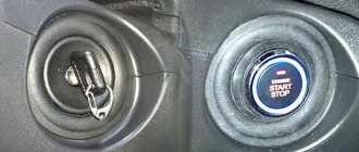
The classic version of the service button is a separate unit. In this case, it is glued with tape and is hidden under the instrument panel, near the mounting block or in another place where it is not noticeable, but at the same time easily accessible if you know the location.
In most StarLine alarms, the service button has exactly this appearance - on old models A61 and A91, modern A93 and A94. However, this design also has a disadvantage: glued to plastic, it comes off over time, knocks on the panel while moving, or gets lost in the depths of the bundles.
Therefore, sometimes on Starline alarms the Valet button is structurally combined with another element, for example, located on the antenna module. Note that the call button, which is found on StarLine antenna modules, should not be confused with it.
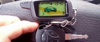
However, in a number of Starline alarms, despite the presence of a separate service button in the installation kit, the call button on the antenna module can also be used as a service button. In this case, the installer may not install the StarLine service button at all. This function is implemented in alarms A63/93, A64, A94, B/D/64/94, E60/90 with firmware older than N2 (the firmware number is indicated on the body of the central unit). The Starline model can also be identified by its keychain.
For alarms where the antenna module button is used as Valet, be sure to set a personal emergency disarming code (see the corresponding article), since otherwise the degree of vehicle security is seriously reduced.
Replacing the emergency stop button on a VAZ
Any owner of a VAZ car has probably encountered problems with the emergency stop button .
The most important of them is the inconvenient location of the standard emergency lights on the steering casing, which is difficult to get to without distracting your eyes.
This is especially inconvenient and even dangerous while driving.
Problems often occur with the built-in lock, when when the alarm is turned on, it is then difficult to turn it off because the button gets stuck. Then you have to completely remove the emergency gang and adjust the latch.
All these difficulties can be easily solved by the new euro button, which can be purchased at any online store. After reading this article, replacing the hazard warning button will not be difficult even for a beginner.
When are you required by law to turn on your hazard lights?
Any driver must press the vehicle's hazard warning light button and activate ACC in several cases:
- If the driver had to stop right in the middle of the road while driving. The need to stop may be due to a breakdown of the vehicle or poor health of the driver. In this case, it is necessary to activate the hazard warning switch until the car comes to a complete stop, otherwise an accident may occur.
- When a car is stopped by a traffic police officer or the driver is blinded by an oncoming vehicle.
- When a driver operates a vehicle with defects that could lead to an accident. Please note that in this case, operation of the vehicle is permitted unless prohibited by current traffic regulations.
- If the vehicle is being towed by another vehicle, the hazard lights should always be switched on, as this will alert other road users.
- In the event that you are transporting children in a car, the corresponding sign is installed on the car, and you are disembarking or picking them up.
- When cars are moving in a convoy, but one of the vehicles is forced to stop. Moreover, if the hazard warning lights are turned on on one car, other drivers are also required to turn them on.
- Naturally, the emergency lights must be turned on if the car is involved in an accident.
A simple alarm scheme
All these situations are regulated by the rules of the road. But there are other cases when activating ACC alone is not enough and the motorist needs to place an appropriate warning triangle on the road. If this sign is not there, it can be replaced with a red light, and this light source should blink similar to an emergency light. The installation of this sign or lantern is placed at a distance of no more than 20 m from the vehicle if the stop was made in a populated area.
If the problem has overtaken you outside the city, then the sign should be installed at a distance of no closer than 40 meters, and this can be done in the following cases:
- If the car is involved in an accident. If this happens, then you need to take into account that the machine can not only be a hindrance to other machines, but also affect their safety. Accordingly, the further away you place the sign, the more time the driver of the other car will have to assess the situation on the road and perform the correct maneuver.
- Another case is if you had to stop where visibility is poor or limited. In such situations, the sign must be placed no closer than one hundred meters from the vehicle, both in front and behind.
How to remove and connect the euro hazard warning button on a VAZ
Before you begin installing the emergency lights, you should familiarize yourself with the connection diagram for the Euro button on the VAZ-2114 (2115) , which we will use as an example.
This scheme allows you to avoid the use of relays and interference with standard wiring.
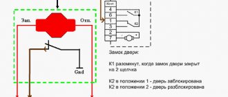
- The connected contacts of the old connector “1” and “3” - to terminal “2” on the emergency button;
- Pin “2” on the button goes to pin “D”;
- Contact “7” – to contact “1” on the button”;
- Pin “B” – to the backlight;
- Conclusions “A” and “C” are mass;
- Pins “8” and “4” in the block of the old connector are bridged.
To replace the hazard warning button we need the following:
- Euro button with a block for it;
- Two 1N4007 diodes;
- Soldering iron;
- Flux LTI-120;
- Screwdriver;
- Two terminals.
Having prepared all the necessary tools, we proceed to replacing the old emergency light using the example of a VAZ-2114 (2115) car and the hazard warning switch 2515 996.3710-07.10 based on the diagram above.
First you need to disassemble the emergency button in the following sequence:- Using a screwdriver, disassemble the steering casing;
- We remove the chip from the old switch and the switch itself from the casing;
- Unscrew the two screws and remove the side panel on the driver's side;
- We extend the freed chip into the window where the on-board computer is usually located;
- We disassemble the old emergency button using a flat screwdriver - it has two grooves, by prying it you can separate it into two parts;
- We keep the block of the old hazard warning connector for ourselves, we can throw away the spring - we won’t need it anymore.
- Then we proceed to connecting new contacts and the switch:
- To obtain a reliable solder, the contact surfaces must first be tinned with LTI-120 acid;
- Contacts “4” and “8” of the chip are immediately connected to each other using wiring;
- To the same chip, to contacts “1” and “3”, we solder two diodes with cathodes to it, and connect the anodes to each other;
- We solder the wires of the new switch from pins “2” and “D” to the free anodes of the diodes;
- In order for the triangular alarm indication icon to flash, we bring the wire of contact “2”, designated in the diagram as “to the dash”, to the instrument panel and connect it to a free contact (do not forget to insert a light bulb into the dash, since it is not provided by the factory);
- We solder the wire going from contact “1” of the emergency button to contact “7” on the chip;
- The remaining contacts of the connected switch “A” and “B” go to ground and backlight, respectively. Take two wire terminals and solder them to pins “A” and “B”. If necessary, this will allow you to remove all the new wires without affecting the old wiring;
- We connect the new wiring harness to the wiring, and connect the free ends of contacts “A” and “B”, to which the terminals were soldered, to the loosely dangling chip on the fog lights.
Connect the ground and backlight, insert the button. All is ready!
VIDEO INSTRUCTIONS » alt=»»>
Note that the bridged contacts “4” and “8” in the block of the old hazard warning switch connector allow you to use the emergency lights even when the ignition is turned off.
This is the only side effect of this connection, but it is insignificant, because no one forces you to turn on the emergency signal when the ignition is turned off.
There is no need to use a relay and, as mentioned above, the button can be disconnected at any time painlessly for factory wiring.
Even a person who is far from such connection diagrams can independently replace the alarm button on a VAZ. Financial costs are minimal, the time for the procedure is a maximum of 30 minutes. Ultimately, your car will have a modern emergency warning system located in a convenient location.
How to turn off the alarm without a key fob
To turn off the alarm without using a key fob, use one of two methods - emergency shutdown and disarming coding. However, in any case, for this you need to know the location of the Valet button, which allows you to switch the alarm to service mode. Otherwise, she will be “on edge,” and it will be impossible to approach her without consequences.
Varieties of “Jack” buttons
You can read about where the “Valet” button is located in your car in the manual or ask the specialists who install the “alarm”. As a rule, alarm installers place them near the fuse box, or under the front dashboard (there are also options when the Valet button was located in the area of the driver's pedals, behind the glove compartment, under the steering column). If you do not know where the button is located, then focus on the location of the alarm LED indicator. If it is installed in the front left side of the cabin, then the button will be there. If it’s on the right or in the middle, then you also need to look for the button nearby.
If you buy a car second-hand, be sure to ask the previous owner about the location of the mentioned button.
The two methods presented (emergency and coded) are so-called “fast” methods. That is, they can be implemented in a matter of seconds without the need to climb and understand the car’s electrical wiring. Next, we will consider these two methods separately.
Options for the location of the “Jack” button
Emergency shutdown
In this case, in order to turn off the standard alarm, you must know the sequence of actions to be performed. As a rule, this is a certain sequence of turning the ignition on and off and several clicks on the mentioned secret Valet button. In each individual case, this will be its own combination (the simplest is to turn the key in the lock and briefly press the button). While you are looking for the secret button and remembering the PIN code, so as not to irritate everyone around you with the howling of your car, you can at least remove the terminal from the battery. The alarm will stop “yelling” and you, in a calm environment, will decide on your actions - either remove the battery and slightly deform it (sometimes it helps when it’s dead), or resort to unlocking by entering a code. Next, we will look in more detail at the combinations for alarms popular among domestic car enthusiasts.
Coded shutdown
The definition of “coded shutdown” comes from an analogue of a PIN code, which has from 2 to 4 digits, which are known only to the owner of the car. The procedure goes something like this:
- Turn on the ignition.
- Press the “Jack” button the number of times that corresponds to the first digit of the code.
- Turn off the ignition.
- Next, steps 1 - 3 are repeated for all numbers that are in the code. This will unlock the system.
However, the exact sequence of actions is indicated only in the instructions for your car or the alarm itself. Therefore, unlock only if you are completely sure that your actions are correct.
Replacing switches and backlights on the instrument panel
Disconnect the wire terminal from the negative terminal of the battery. To replace the trunk lock drive switch, remove the cover of the mounting block from the instrument panel (see “Replacing fuses and relays”).
Use pliers to squeeze the two switch latches...
...and remove the switch from the cover of the mounting block.
Trunk lock drive switch (the arrow shows the lock, the other lock is not visible in the photo). Install the trunk lock actuator switch in the reverse order. To replace the external lighting switch, remove the cover of the mounting block from the instrument panel (see “Replacing fuses and relays”).
Using a Phillips screwdriver, unscrew the screw securing the switch.
We remove the switch from the instrument panel by tilting the upper part of the switch towards you.
Squeeze the two clamps of the wiring harness block...
...and disconnect the block from the switch.
Outdoor lighting switch. Install the outdoor lighting switch in the reverse order. To replace the hazard warning switch, remove the central trim from the instrument panel (see “Removing the instrument panel”).
Disconnect the wiring harness block from the switch.
Squeeze the two switch latches...
...and remove the switch from the instrument panel trim.
Hazard switch (arrows indicate clamps). Install the hazard warning switch in the reverse order. To replace the rear window heating switch, remove the central trim from the instrument panel (see “Removing the instrument panel”).
Comments
Submitted by Guest Thu, 24/11/2011 — 17:57 Permalink
The VALET service mode is provided in almost all modern car alarms. The functionality of this mode differs for different alarm models.
p, blockquote 1,0,0,0,0 —>
p, blockquote 2,0,0,0,0 —>
The main purposes of the service mode are:
p, blockquote 3,0,0,0,0 —>
p, blockquote 4,0,0,0,0 —>
leaving the car for repairs at a service station with the security alarm turned off;
emergency disarming of a vehicle with a lost or faulty key fob;
making special settings for security functions (in some car alarm models);
prescribing additional key fobs.
Replacing the light bulb in the hazard warning button
Work should be carried out on a well-warmed-up car, since cold plastic becomes very fragile and the likelihood of breaking plastic fasteners and pistons greatly increases.
To replace the light bulb in the hazard warning button, you first need to remove the instrument panel visor, take out the glove compartment, and remove the radio. After this, you need to remove the handles of the climate control unit, pulling them towards you with quite a lot of force. Now you need to remove the plastic trim of the center console by pulling it towards you. Behind it, in its upper part, there are two self-tapping screws. They need to be unscrewed.
Now you need to completely remove the entire decorative glossy panel. You need to start pulling from the instrument panel, gradually moving towards the passenger. Next, you need to press the petals of the emergency light button and pull out the button. You need to remove the lamp socket from the button, replace the lamp and reassemble everything in reverse order.
Many of my light bulbs have burned out. In the hazard warning button, in the automatic transmission illumination and transfer case illumination, and also in the heater/air conditioner blower power knob for the rear passengers.
I decided to start with the hazard warning button.
1. You need to remove the air duct cover. We hook up the corners marked in the picture and remove the casing, don’t be afraid, nothing will break:
To watch online, click on the video ⤵
Lada Kalina emergency light does not work Read more
How to remove the center console trim of the Lada Kalina instrument panel Read more
Faulty turn signals LADA Kalina 8 valves Read more
Removing the EMERGENCY BAR button Lada Granta More details
Turn signals and emergency lights do not work on Kalina 1 Read more
USEFUL modification for Grants - “polite” turn signals and emergency lights. More details
How to remove the hazard warning button on a Lada Priora Read more
Kalina 2 turn signals do not work. Replacement of CBKE Read more
GaraGe D21 // Replacing the turn signal RELAY in LADA KALINA VAZ 1118 // Life under the viburnum // Read more
We disassemble part of the front panel of Kalina 2 Read more
Replacing the emergency flasher fuse on a VAZ - Lada Granta More details
Course "Auto Electronics". Turn signal relay Read more
Top 5 modifications to Lada Kalina. More details
Lada Kalina 2 in every detail Read more
Replacing the backlight lamps of the Lada Kalina heater Read more
We tighten the Lada Kalina dashboard Read more
Replacing the lamp at the hazard warning light button
I decided to replace the hazard warning light button bulb because it was burned out. Actually, it hasn’t been on for me since I bought the car, I didn’t even know about its existence at first. And now, after driving for 2 years, I decided to fix this problem.
1. First, remove the visor above the speedometer, unscrew 2 bolts and discard it. For those whose PTF button illumination lamp does not light up, you can replace it at the same time!
2. We remove the glove tray so that later it will be more convenient to thread the radio wires, and it is also convenient to push it out through this tray.
3. We remove the radio and then there is an ominous silence...
4. Smoothly but confidently pull out the air flow temperature regulator, flow speed regulator and air flow direction regulator. We also remove 2 screws.
5. Remove the panel, overcoming the resistance of the pistons. If the car is cold, it is better not to touch anything; the likelihood of breaking delicate and fragile Japanese latches and pistons increases significantly.
6. We don’t get confused by the resulting picture, but take a screwdriver and unscrew 2 screws, which are indicated by red circles:
7. Carefully pull the entire trim towards you from the speedometer towards the right passenger door. When all the pistons snap off, disconnect the 2 wire blocks, the clock and the emergency gang.
8. Feel for the emergency light button, press on the petals and push it out. Only one petal is visible in the photo.
Ignition system diagram Lada Kalina Lux
1 — oil pressure warning lamp sensor;
2 — coolant temperature indicator sensor; 3 — additional fuse block; 4 — fuses for the electric fan of the engine cooling system; 5 — electric fuel pump relay; 6 — relay for the electric fan of the engine cooling system; 7 - ignition relay; 8 — relay 2 of the electric fan of the engine cooling system; 9 — relay 3 of the electric fan of the engine cooling system; 10 — electric fan of the engine cooling system; 11 — throttle position sensor; 12 — idle speed regulator; 13 — coolant temperature sensor; 14 — diagnostic block; 15 — ignition system harness block to the instrument panel harness block; 16 — solenoid valve for purge of the adsorber; 17 — speed sensor; 18 — ignition system harness block to instrument panel harness block 2; 19 — mass air flow sensor; 20 — crankshaft position sensor; 21 — oxygen sensor; 22 - controller; 23 — rough road sensor; 24 — diagnostic oxygen sensor; 25 — ignition coil harness block to the ignition system harness block; 26 — ignition coils: 27 — ignition system harness block to the ignition coil harness block; 28 — spark plugs; 29 — nozzles; 30 - resistor; 31 — air conditioning system pressure sensor; 32 — blocks of the ignition system harness and injector wiring harness; 33 - phase sensor; 34 - knock sensor. Ignition system wiring harness -11184-3724026-10. Ignition coil wiring harness -1118-3724148-00. Injector wiring harness -11184-3724036. A - to the “plus” terminal of the battery.
