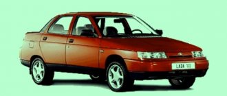
The relatively low-cost model of domestic production is extremely common among motorists in the CIS countries due to the low cost and sufficient cross-country ability of the crossover. The lightweight SUV stands out among its peers due to its combination of performance and minimal price.
A separate topic of conversation is the reliability of the car. Electronic components and assemblies of a machine often fail due to insufficient reliability of electronic components. The circumstance gives rise to questions among car enthusiasts about what the pinout of a Chevrolet Niva looks like and how its design can be repaired.
Electrical wiring components
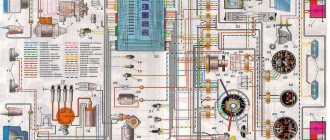
The standard Niva Chevrolet wiring diagram is divided into several sections for better maintainability and ease of maintenance.
- Front part - a set of cables connects all equipment located in the engine compartment of the car.
- The interior part - the unit is additionally divided into independent zones, which allows you to power different groups of equipment without the risk of damaging or overloading the main elements.
- Instrument panel compartment - a bundle of cables combines the lines from all gauges, sensors and indicators.
- The stern assembly - the bundle is responsible for voltage and control of equipment located on the rear side of the vehicle.
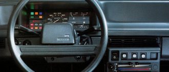
General appearance and varieties
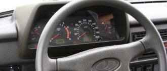
At the moment, there are several options for the instrument panel on the Niva Chevrolet and Niva Treval.
| Picture number | Years of manufacture | Applicability | Catalog number |
| 1 | 2006-2007 | Chevrolet Niva | 21230-3801010-00 |
| 2 | 2006-2009 | Chevrolet Niva | 21150-3801010-00 |
| 3 | 2009-2018 | Chevrolet Niva | 21230-3801010-10 |
| 4 | 2018-2019 | Chevrolet Niva | 21230-3801010-15 |
| 5 | 2019-2020 | Chevrolet Niva | 21230-3801010-17 |
| 6 | 2020… | Lada Niva Travel | 21230-3801010-17 |
Despite the external differences, these shields differ only in appearance, lighting, software and functions of the built-in BC. Otherwise, the icons and designations of these panels are absolutely the same.
Pinout of Niva Chevrolet connectors responsible for the front part of the wiring
- 1/6 – front right/left headlight block;
- 2 – joint assembly of the machine starter;
- 3 – voltage supply for traction starter;
- 4 – battery connection terminals;
- 5 – generator module for powering the electrical circuit;
- 7/15 – units for combining head optics fog lights;
- 8 – contact group for the drive of the electric motor for the front windshield washer;
- 9 – input of a temperature sensor that measures indicators outside the vehicle;
- 10 – contact plug for the engine compartment lighting lamp;
- 12 – standard sensor for measuring the remaining brake fluid level;
- 13 – plug of the standard electric motor for driving the windshield wiper;
- 14 – designation of a standard horn;
- 16/17 – plug inputs to the dashboard.
Additional relay and fuse box
It is located behind the glove compartment at the feet of the front passenger. To access, unfortunately, you will have to remove the glove box. The fuses for the electric fans of the cooling system and the engine control relay (injection system) are located here.
p, blockquote 42,0,0,0,0 –>
Scheme
p, blockquote 43,0,0,0,0 –>
p, blockquote 44,0,0,0,0 –>
Purpose
p, blockquote 45,0,0,0,0 –>
- Additional relay (turns on the right electric fan through an additional resistor at low rotation speed);
- Fuse (50A) protecting the power circuits of the additional relay and the right electric fan relay;
- Fuse for the fuel pump (fuel pump) (15A), protecting the power circuits of the electric fuel pump relay;
- Fuse (15A) protecting the constant power supply circuit of the controller;
- Right electric fan relay;
- Left electric fan relay;
- Electric fuel pump relay;
- Main relay;
- Fuse (50A) protecting the left electric fan circuits;
- Fuse (15A) protecting power circuits switched on by the main relay;
- Controller
Chevrolet Niva wiring diagram, part of the ECM
- 1 – spark plug pins;
- 2 – contact group of injector drivers;
- 3 – ignition unit;
- 4 – control controller;
- 5 – main protective relay of the internal combustion engine;
- 6 – area for location of fuse links;
- 7 – main relay fuse;
- 8/9 – protective circuits of the right and left head fans of the radiator;
- 10 – protective element for the control fuse of the main fuel pump;
- 11 – controller circuit fuse;
- 12 – secondary protective element of the main radiator fan on the right side;
- 13 – auxiliary fuse of the above circuit;
- 14 – fusible link of the fuel pump control circuit;
- 15 – fan of the main radiator, located on the left side;
- 16 – standard oxygen concentration sensor in the intake manifold;
- 17 – drain output of the detonation channel meter;
- 18 – DPKV output;
- 19 – control by the adsorber purge valve;
- 20 – output of the mass air flow sensor group;
- 21 – idle speed control drive;
- 22/23 – activation of the left/right fan motor of the main engine cooling system;
- 24 – auxiliary resistor;
- 25 – control of the TPS device;
- 26 – output from antifreeze temperature sensor;
- 27 – status indicator of the above-described sensor;
- 28 – standard module for measuring lubricant pressure in the crankcase compartment of the power plant;
- A/B – battery terminal blocks;
- C – “mother” input for connecting to the dashboard;
- G1/G2 – grounding outputs of the wiring section.
Possible faults
If you understand the designations of the light bulbs in the Niva Chevrolet instrument panel, let's look at the next point - possible malfunctions of the device:
- The instrument cluster does not work, but the engine starts normally. Most likely, the problem is caused by either a failure of the shield itself or a lack of power.
- The lights on the instrument cluster do not light up. If all the indicators stop working at once, this may indicate a break or fraying of the wire responsible for the lighting. If only some of the lamps do not work, then most likely they are simply burnt out.
- Devices not working - speedometer or tachometer. Most likely this is an electrical type problem; you need to disassemble the panel and look for the fault.
- Sensors do not work - fuel level, antifreeze temperature. As practice shows, this usually indicates poor contact in the electrical circuit. Usually this problem is solved by disconnecting and cleaning the plug contacts (the author of the video is the Ig K channel).
DIY diagnostics
In accordance with the service manual for the car, the control panel has its own diagnostic system, which allows you to check the device without removing it.
The sequence of actions for diagnosis is as follows:
- The ignition must be turned off and the daily mileage reset button must be pressed. Next, the ignition is turned on and the key is released. The arrows on the tidy devices must pass through the entire scale several times - this is a tidy test.
- Then hold down the reset button for five seconds - this will clear the processor memory.
- Now press the odometer reset button; the version of the software used should appear on the display. When you press the button again, numbers should appear on the display. The number 0 indicates that there are no malfunctions in the operation of the device, 1 - the microprocessor has failed, 2 - the fuel controller circuit has broken, 4 or 8 - increased or decreased voltage in the on-board network. If there are several breakdowns, the sum of codes will appear on the screen. For example, 14 is errors 2, 4 and 8, fault 10 is errors 8 and 2, etc.
Niva electrical circuit responsible for the equipment built into the front doors
The following is a general breakdown of the electrical equipment of Chevrolet Niva car doors manufactured after 2009. The representation is based on the fact that both sides are almost identical:
- 1/10 – door position limit switches;
- 2/11 – drive of electric window regulator gearboxes;
- 3/12 – plugs for control drives for adjusting the position of rear-view mirrors;
- 4/13 – door lock gearboxes;
- 5/14 – standard terminal blocks for the speaker outputs of the standard acoustic module;
- 6/15 – window switch drives.
About the main elements of an electrical circuit
The vehicle's electrical circuit includes the following components:
- Sources of electrical energy.
- Devices responsible for its consumption.
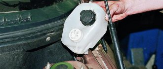
Energy sources
The generator together with the battery is responsible for this function . The rotation of the generator will be forced while the engine is running. The voltage generated is much higher compared to the on-board network. It ranges from 13.2 to 14.7 Volts. This value is enough for a stable charge of the battery, providing the necessary voltage to all units inside the car. Thanks to this, any Chevrolet Niva electrical circuit works stably.
Consumers
These can be individual devices or whole blocks . It is assumed that each block is equipped with its own fuses. Thanks to this, systems become more reliable and secure.
Types of fuses with different resistance ratings are mounted , and they are combined in one place. The fuse box is standardly located inside the passenger compartment; almost all electrical circuits pass through it. The exception is those parts that are responsible for starting and charging engines.
The most powerful consumers are the following:
- Charger socket or cigarette lighter.
- Dashboard.
- Heated rear window with power windows and windshield wipers.
- Lighting. This includes all sources from which light comes. And those that work from the on-board network. Usually we are talking about low and high beam lamps, side lights, direction indicators, and so on.
- Starter. With his participation, the engine starts automatically using a special system of gears connected to the flywheel. 1.5 kW – rated current power, with a total power of 80A. A description of the exact characteristics is always in the official instructions.
In general, the scheme looks like this (see the video at the end of the article for details):
Niva electrical circuit responsible for the equipment built into the cargo compartment door
- 1 – output of the contact group of the rear bundle of highways;
- 2 – door position limit switch;
- 3 – central locking gearbox;
- 4 – voltage for the rear windshield washer motor;
- 5 – plug for additional brake sign;
- 6 – heated aft windshield;
- 7 – stern glass wiper controller;
- 8 – relay of the above element.
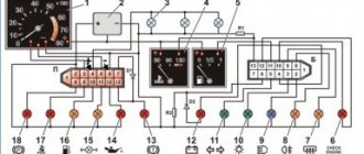
Instrument panel pinout
Here is a description of the terminals and terminals of standard instrument panel wiring:
- 1 – diagnostic output, located on the underside of the board under the steering wheel;
- 2 – plug connector for connecting the ECM;
- 3/4 – standard modules for connecting the front connection of the cores responsible for the engine control systems;
- 5/7 – left and right steering column switches;
- 6 – ignition switch device connector;
- 8 – instrument panel combination;
- 9 – output for powering the connector of the contact group of the interior ventilation and heating system;
- 10/11 – lighting plugs for the above equipment;
- 12 – button switch of the alarm device;
- 13 – mounting box for fuse insertion;
- 14/15 – the lamp itself and the button to turn off the lighting of the glove compartment;
- 16 – contact pin for turning off the brake lights;
- 17 – switch of the standard sound warning module (horn);
- 18 – automatic protection of fog lights of head optics;
- 19 – automatic window lifters;
- 20 – protective relay for sound signal;
- 21 – safety module for the seat heating system;
- 22 – starter control relay;
- 23 – switch for the external lighting system;
- 24 – contact group for connecting the stove fan;
- 25 – built-in switch for turning on the heated windshield;
- 26 – device for turning off the front fog lights;
- 27 – switch for stern lights, fog lighting group;
- 28 – air conditioner setting button;
- 29 – position regulator of heating manipulators;
- 30 – cigarette lighter pin;
- 31 – buttons for adjusting the direction of the light flux of the head optics;
- 32 – adjust the brightness of the instrument panel illumination;
- 33 – auxiliary resistor mechanism of the heating fan;
- 34 – standard immobilizer module;
- 35/36 – standard-type onboard acoustic module terminals;
- 37/38 – terminal connectors for connecting the rear harness of the on-board circuit.
How to change a light bulb in a panel on a Niva?
To replace the lamp in the dashboard on a Chevrolet Niva, you need to remove the panel from the car. To do this, dismantle the cladding and then remove the shield.
Unfold the shield and find the required cartridge. Remove the cartridge by turning it counterclockwise. You need to remove the baseless lamp from the socket and install a new one in its place:
After this, you need to install the shield in its original place and reassemble it in the reverse order.
Wiring diagram of the VAZ Niva, the part responsible for powering the head optics
- 1 – main lighting device;
- 2 – fuse box;
- 3 – headlight switching regulator;
- 4 – part of turning off the ignition;
- 5 – headlight switches;
- 6 – designation in the instrument cluster of the area responsible for turning on the high beam;
- K4/5 – protective relays for turning on the high- and low-range modes of the head optics;
- A – terminal pins going to the circuit’s power source.
Instrument panel "APS" COMFORT VAZ 2121-2131 /Niva/ (for instrument cluster VAZ 21213)
APPLICABILITY: VAZ 2121, 21213, , 2131 (Niva) with instrument cluster VAZ 21213.
Original design of the COMFORT
, designed specifically for the LADA 21213 and subsequent versions of NIVA
.
This instrument panel is also suitable for earlier versions, provided that the requirements set out below are met.
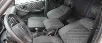
Instrument panel "APS" COMFORT
qualitatively improves the interior space of the car, creating additional convenience for the driver and passenger. Ergonomic location of the radio in the upper part of the panel. Convenient layout of control keys. Increased volume of the glove box and area of the lower shelf.
There is a recess for things on top of the panel and an additional shelf for small things on the heater block. Divided central air duct of increased cross-section.
Instrument panel "AutoPolymerService"
designed in such a way that no modifications are made during installation and that existing controls and instruments are used.
The frame is made of ABS plastic with metal reinforcements and brackets, which in turn makes the panel safer during impacts and more durable due to elasticity and uniform thermal expansion when heated.
The hinged parts are made of hard and black ABS plastic, the coating is identical to the instrument panel as a whole.
Method of installation and fastening - in standard places: on top with studs, four M6 nuts, from below with self-tapping screws into the reinforcing beam. The heater unit (console) of the instrument panel is fixed from below to the floor tunnel.
The kit includes:
- 1. Instrument panel;
- 2. Combination shield;
- 3. Radio panel;
- 4. Heater unit (console);
- 5. Glove box;
- 6. Shelf;
- 7. Additional air ducts – 2 pieces;
- 8. Air duct deflectors (central) – 2 pieces;
- 9. Set of fastening parts.
Pinout of contacts of the Niva Chevrolet fuse mounting block
The car is supplied to the market with several types of mounting blocks. The exact type of device depends on the configuration of the vehicle and its year of manufacture. Further description is given using the example of Bosch M,1,5,4:
- 1 – cylinder ignition system;
- 2 – empty;
- 3 – fuel pump connection contact;
- 4 – stepper motor;
- 5 – free;
- 6 – connection of the main power plant cooling fuse;
- 7 – incoming pulse from the MRI;
- 8 – empty;
- 9 – standard speedometer;
- 10 – not busy;
- 11 – knock sensor;
- 12 – voltage supply for sensors;
- 13 – L-line;
- 14 – weight on the body from the injectors;
- 15 – control of injector drives for cylinders 1-4;
- 16/17 – not used;
- 18 – power supply of devices from 12 volts;
- 19 – common ground cable for electrical appliances;
- 20 – ignition supply to cylinders 2 and 3;
- 21 – stepper motor terminal;
- 22 – engine check lamp;
- 23 – empty;
- 24 – mass of the stepper motor;
- 25 – air conditioning system relay output;
- 26/29 – stepper power plant;
- 27 – voltage to terminal No. 15 of the ignition switch;
- 28 – empty;
- 30 – mass of motor control sensors;
- 31/32 – not applicable;
- 33 – control of settings of injector drivers for cylinders No. 2/3;
- 34-36 – empty;
- 37 – device for powering the main relay;
- 38-40 – not used;
- 41 – submitting a request for an air conditioning module inside the cabin;
- 42 – empty;
- 43 – tachometer control signal;
- 44 – signal supply from the potentiometer;
- 45 – DTOZH;
- 46 – control of the main relay;
- 47 – device for confirming admission to ECU programming;
- 48 – low level of impulse from DPKV;
- 49 – opposite meaning;
- 50-52 – empty;
- 53 – receiving an impulse from the TPS;
- 54 – fuel consumption detail;
- 55 – K-line.
Ignition system harness
The ignition system ensures the formation of a spark in the cylinders according to the power strokes. In modern engines, wires are connected to sensors that monitor ignition, engine temperature and other parameters.
The ignition system harness 2123 (commonly called “braid”) is indicated in blue in the figure.
In the cabin, it connects to the controller (“brains”), instrument panel, ground and wire from the rear harness. Exiting into the engine compartment, it is divided into two wires.
The largest one is directed to the radiator and along the way it is connected to the mass air flow sensor, crankshaft sensor, resistor, and electric fans.
Throwing over the power steering pump, wires extend from the core to the phase sensors, idle speed, throttle valve, detonation and injectors. This wiring controls the operation of the engine and ensures its smooth functioning.
The second wire runs upward and is divided into two: wires go to the right to the plus and minus of the battery, and to the left to the adsorber, fuel pressure sensor and oxygen sensor.
On models with air conditioning, a branch goes from this harness to its fuse.
If at least one wire in the “braid” is short-circuited, there is a big risk that you will not be able to start the engine. The controller simply will not see information about its temperature, fuel supply to the injectors or throttle position.
In this case, it is better to immediately replace the entire harness than to contact a diagnostician, look for one wire and replace it if the result is questionable.
N
The figures show a diagram of the car before restyling (2009). For newer models, only the direction of the harnesses has changed - the sequence and connection diagram remain the same.
Prevention
To prevent breakdowns, the manufacturer recommends following several tips.
- Once a year, treat all terminals and connectors with special oil - this will prevent the formation of oxides.
- Periodically check the tightness of the contact connectors. If the connections are loosened, short circuits may form or the conductivity of the circuit may decrease, which will be perceived by the ECU as a mechanism failure.
- Check the degree of wear of power cables and lines. During active use of the vehicle, braids made of flexible polymer may wear out and crack. This circumstance can provoke short circuits and mechanical shedding of insulators. Therefore, it is better to prevent a breakdown than to fix it.
If you adhere to the above rules, the car will serve for a long time and with high quality all the time.
Connection between battery and starter
Each car has its own starter installation scheme. There may be several access options :
- on right;
- left;
- from the radiator side;
- from the salon side.
It is often necessary to use a lift or inspection pit to reach this component. The mechanism is needed to ensure engagement between the gear and the flywheel. Therefore, the device is most often located in the area where the clutch housing is attached. The electronic version is no exception.
For connection, only one connector is used , to which a special terminal is added. The starter starts working every time the owner turns the key.
It is best to use a multimeter to detect breakdowns in one of these parts of the car. But faults can be easily determined using other simple manipulations.
In most cases, repairing the starter is possible, even if such an important part as the windings has failed . The electrical equipment of a car in most areas is subject to complete restoration.