The VAZ 2105 model first appeared on city streets in 1980 and immediately became extremely popular. The fact is that the design of the car repeated the features of European models of those years: front and rear headlights, aluminum bumpers, and a modern instrument panel.
All this required the designers to rework the usual electrical circuit of the car.
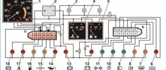
Factory wiring diagram for VAZ 2105 included with the car
The original diagram published in the article will make it easier for car owners and service station technicians to find faults in the electrical system of a Zhiguli family car.
The VAZ 2105 wiring diagram together with a verification tester will allow you to:
- determine the causes of circuit failure;
- identify which sensor or relay has stopped performing its functions;
- establish a breakdown in the ignition system;
- identify the circuit whose fuse has blown;
- check the on-board voltage supplied by the generator;
- find the cause of failure of incandescent lamps, etc.
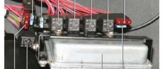
Wiring for a VAZ 2105 in the process of diagnosing
Instrument panel and controls of VAZ-2107
1 — switch lever for windshield wipers and washers of the windshield and headlights. It is energized if the key in the ignition switch is in position I or III. At lever position:
2 — sound signal switch. Constantly under voltage. 3 — direction indicator switch lever. It is energized if the ignition key in the ignition switch is in position I. When the lever is moved to position “A”, the right turn indicators are turned on, and in position “B” - the left turn indicators. When the car enters the straight line after a turn, the lever automatically returns to its original position. This operation can also be performed manually. 4 — headlight switch lever. When you press the external lighting switch 17 to the second fixed position and if the key in the ignition switch is in position I or III, and the switch lever is in position:
5 - side nozzles of the interior ventilation and heating system. 6 — headlight hydraulic corrector. By rotating the handle, depending on the vehicle load, the angle of the headlight beam is adjusted so that oncoming drivers are not dazzled.
7 — engine hood lock drive lever. 8 — socket for connecting a portable lamp.
10 — alarm switch. When you press the button, all direction indicators and the warning lamp in the button itself turn on. The hazard warning lights turn off when the button is pressed again.
11 — clutch pedal. 12 — brake pedal. 13 — heater cover lever. 14 — switch (rheostat) for instrument lighting. Is energized when the external lighting is on. Rotating the handle turns on the lighting of the devices and adjusts their brightness. 15 — accelerator pedal. 16 - place for the radio. 17 — external lighting switch. When you press the upper arm of the key before the first fixed position, the side lights and license plate lights are turned on, and before the second, the headlight circuits are additionally energized. In a variant, a switch is installed. 18 - rear fog light switch. The lights in the rear lights are turned on in conditions of limited visibility (snow, fog, etc.) by pressing the upper arm of the button with the headlights on. In this case, the lamp in the key itself signals that the lights are turned on and simultaneously illuminates the key. 19 — parking brake lever. By moving the lever up, the brake pads of the rear wheels are activated. To return the lever to its original position, you must press the button at the end of the lever handle. In case of emergency, the parking brake can be used while the vehicle is moving to slow down, or used simultaneously with the service brakes. 20 - backup warning lamp. In the variant version, if the car is equipped with seat belts with an alarm for driver unfastened seat belts, a “Fasten seat belts” warning lamp is installed. 21 - backup warning lamp. On a car equipped with a fuel injection system, the “CHECK ENGINE” warning lamp is connected (check engine). A short-term lighting of the lamp when the ignition is turned on indicates a self-test of the system and is not a sign of its malfunction. 22 - rear window heating switch. The rear window heating is turned on by pressing the upper arm of the button with the ignition on. 23 - plug. 24 — gear shift lever. The gear shift diagram is printed on the lever handle. 25 - hours. To move the hands, pull the handle towards you and rotate it counterclockwise. 26 - cigarette lighter. To use, you need to press the button on the cartridge, which after about 15 seconds automatically returns to its original position, ready for use. When the instrument lighting is turned on, a special lamp illuminates the cigarette lighter socket. 27 - indicator lamp for turning on the heated rear window. Lights up orange when the rear window heating is turned on.
28 — control lamp for the fluid level in the hydraulic brake reservoir. The lamp lights up with a constant red light if the fluid level in the reservoir has dropped below the permissible limit due to fluid consumption or due to system damage. To check the serviceability of the lamp itself, it lights up if the parking brake lever is raised. 29 - ashtray. 30 — glove box cover. To access the glove box, you need to turn the lock handle clockwise and open the lid. If the key in the ignition switch is in position I or III, the inside of the box is illuminated with a special flashlight. 31 - storage shelf.
Pinout of the old instrument cluster (with oil pressure indicator)
In addition to the presence of an oil pressure indicator, it is worth noting that this instrument panel does not have an air damper indicator lamp (choke), and the emergency oil pressure lamp is located next to the pressure indicator. Because of this, it contains lamps for low brake fluid levels and fog lamps.
White 6-terminal block X1:
- Gasoline level sensor
- Turn signal indicator lamp
- Battery charge sensor (voltmeter -)
- Gasoline level warning lamp
- Overall plus (+)
- Battery charge sensor (voltmeter +)
White 8 terminal block X2:
- Fog lamp warning lamp
- High beam warning lamp
- Dimensions indicator lamp
- Empty
- Battery charge indicator lamp
- Brake fluid level warning lamp
- Empty
- Parking brake warning lamp (handbrake)
Orange 6-terminal block X3:
- General minus (-)
- Tachometer
- Instrument lighting
- Oil pressure sensor
- Oil pressure warning lamp
- Coolant temperature sensor
Difficulties in repairing electrical equipment
The biggest problem that can arise during repair work on a VAZ-2105 is a mismatch in the color of the wiring with that indicated in the diagram.
If the car is many years old, then most likely the wiring has been replaced many times. The previous owner of the car was unlikely to be concerned that the wiring colors did not match the colors in the diagram. Most likely, if a car needed urgent repairs, the first wires that came to hand were installed on it. Therefore, a new car owner will have to face difficulties and figure out which wire is connected where. In this case, you can immediately make some adjustments for yourself in the future using felt-tip pens. During repairs, you can paint each wire in the desired color, this can save time for the next inspection or diagnosis. Another difficulty that a car owner may encounter when repairing a VAZ-2105 is partial replacement of the wiring. The previous owner could only replace part of the wires, thereby causing the current owner a lot of trouble. This situation causes even more confusion, and in this case it would make more sense to simply replace all the wiring.
The most common reason for a VAZ-2105 breakdown is damaged wire insulation or lack of contact. In this situation, it is necessary to test all sections of the wiring using a special device. The non-working electrical wiring is replaced with a new one, or part of the non-working wire can be replaced. If the insulation is damaged, then use electrical tape to eliminate this problem.
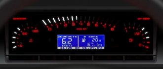
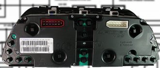
Pinout of the dashboard of VAZ2113, 2115, 2114
There are 26 contacts on the VAZ-2114 instrument panel, each of which is responsible for the operation of this panel indicator. If each contact is supplied to the panel, then the plus contact demonstrates information about which state the car is currently in.
White block (X1)
Red block (X2)
In addition, special indicators and feed sensors are installed on the instrument panel, and the signals are controlled by the panel using a special electronic unit. Having disassembled the instrument panel, you can see that there are two pads inside it: red and white. And all inputs, fuses and outputs are connected to the plug. If the sensors fail, they will need to be replaced. It is also better to replace damaged or oxidized wires. Controls, like light bulbs and any others, sometimes burn out. it is necessary to undoubtedly replace them with whole ones. Along with them, the lamp sensor often burns out.
VAZ 2114 panel instrument connection diagram
- rear window heating switch;
- rear fog lamp switch;
- light switch for headlights and direction indicators;
- mounting switch;
- windshield wiper unit;
- fog light switch;
- indication block of the on-board control system;
- instrument harness panel block to additional harness;
- combination block;
- instrument panel harness to harness block;
- on-board computer instrument panel harness to system ignition harness;
- instrument panel harness connector to side door harness;
- fuse 16 A;
- fuse 16 A;
- switch switch;
- ignition for lighting;
- heater electric motor;
- additional electric motor heater resistance;
- relay lock unloading relay;
- ignition of rear fog lights;
- relay socket;
- starter for connecting a portable lamp;
- cigarette lighter;
- harness of the instrument panel block to the glove box lamp lighting wiring harness;
- illuminator;
- illuminator;
- switch;
- heater light;
- instrument lighting regulator with switch;
- brake signal rheostat;
- sound switch;
- alarm signal;
- pablo heater control illumination lamp;
- fuse 16 A;
- heating relay Useful;
Another scheme for pinout of connectors
- checking the brake fluid level indicator. If you apply +, the brake light will come on. You can connect it to the red ignition wire of the lock, then, just like on the 2110/lamp 2114, the lamp will be checked when turned on.
- starter hazard warning lamp, the + lamp will light up.
- high beam supply, connect to the green-black wire.
- fuel level indicator, connect to the red-pink wire.
- to the speed sensor.
- signal speed output to the on-board computer. If it is there, then take the speed signal from this contact.
- Brake fluid level indicator, connect to the pink-blue lamp near the wire above the cigarette lighter. In the VAZ-2107, the lamp works the other way around: the sensor connects the lamp to the ground and lights up. You will have to either leave the lamp there where it is, or in the new unit, solder the lamp to + and swap places when (diodes in this case, to check the lamp, you need to connect 1 contact to ground, for example to a lamp or), connect the black wire to the handbrake sensor on the tank, and instead remove the orange one from the block or, EPHH blue from the ignition coil, while the diode in the wiring (between the beard and the glove compartment) must be disconnected, if this is not done, there will be a short circuit.
- left turn lamp, connect to the black-blue wire of the steering column switch pad.
- right turn signal lamp, connect to the blue wire of the steering column switch block.
- instrument lighting, connect to the white wire.
- ground, connect to the black wire.
- devices power supply, connect to the orange wire.
- if the device is simple (without microcircuits, etc.), then connect it to the blue-red wire (fuel reserve lamp), if the tachometer has a display, then connect it to the sensor (temperature from the VAZ-2114, one contact to the other, tidy to ground, place it either in the engine compartment or in the engine compartment, but so that it is far from the engine and so that the wind does not blow).
- ground, connect to the white-black wire.
- low voltage tachometer input (from the ECM), brown to connect-blue wire.
- high-voltage coil input (from the tachometer), connect to the brown-blue wire.
- If there is a display under the speedometer, then connect it to the white-red wire at the brake light switch.
- coolant temperature gauge, connect to the green-white wire.
- outdoor lighting lamp, connect to the yellow wire.
- Connect the choke cover lamp of the carburetor to the gray-orange wire.
- go to the ECM lamp. If the machine is injection, then connect one of the contacts to the orange wire, and the other to the remaining one.
- the lamp goes to the ECM. If the machine is injection, then connect one of the contacts to the orange wire, and the other to the power supply.
- connect the remaining devices to the orange-blue lamp.
- handbrake wire, connect to the brown lamp.
- battery charge wire, connect to the brown-white wire.
- Low oil pressure lamp, gray to connect-blue wire.
Installation and repair instructions
Dismantling the control panel may be required for repairs, tuning the panel, replacing sensors, etc. The procedure is simple and can be performed at home.
Tools and materials
To disassemble and repair the dashboard, you must prepare the following tools and materials:
- a set of keys;
- Screwdriver Set;
- diagnostic tester;
- new sensors and parts needed for replacement;
- elements for tuning.
It is better to buy originals to avoid fakes.
Algorithm of actions
To dismantle the tidy, you need to perform the following steps:
- Turn off the power supply to the machine by disconnecting the negative terminal from the battery.
- After unscrewing the mounting bolts, you need to remove the casing from the steering column.
- By removing the plugs and unscrewing two screws, the instrument panel is removed.
- Next, the wire plugs are disconnected.
- After opening the glove compartment, you need to unscrew the mounting bolts. The bolts securing the shelf for things are unscrewed in the same way.
- By pulling the handle of the hydraulic light corrector, you need to remove it. Then, using a socket wrench, unscrew the mounting nut and push it in.
- In the glove compartment, disconnect the power cord for the backlight lamp.
- After unscrewing the two bolts, you need to move the heater control unit.
- Next, you should dismantle the air duct.
- The next step is to unscrew all the console fasteners.
- When the last two fastening nuts in the center are unscrewed, you need to carefully remove the panel from the studs and remove it from the interior.
Next, the necessary repairs, tuning, replacement of sensors are performed, and backlighting is installed. After completing all the manipulations, the assembly of the device is carried out in the reverse order of disassembly.
To make assembly easier, during disassembly you should mark the wires and sort the devices and sensors.
What you will need:
- Leather substitute or leather, a piece of at least 2x2 meters.
- Hot melt adhesive or other suitable adhesive for leatherette and leather, for example, Kleiberit.
- Construction hairdryer.
- Brushes and knife.
Of course, covering a dashboard with genuine leather is very expensive, but it is resistant to mechanical damage and has a more presentable appearance than other materials. But you can also make tuning of the dashboard using artificial coatings. The main thing is to choose the right color and texture so that the car looks stylish and not like a gypsy car. The ideal option would be leatherette. It is easy to work with and has a fairly wide selection of colors.
Malfunctions of the ignition coil of VAZ 2106
There are individual malfunctions of the ignition coil that lead to replacement of the product. These include external mechanical deformations of the product and breaks in the coil windings. A malfunction of the VAZ 2106 ignition coil is classified as a condition when the ignition coil heats up to a high temperature.
Slight heating of the product is the normal state of this part when the ignition is turned on and the distributor contacts are closed with a contact ignition system. If you doubt the functionality of this part of the ignition system, we recommend checking the coil for the resistance of both windings of the product.
conclusions
Differences in vehicle modifications often lead to confusion when servicing electrical components. This is why when servicing yourself it is so important to use the original diagram related to a specific car model. This will not only avoid problems, but will also make troubleshooting easier.
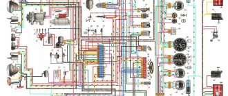
Free reference material on the electrical equipment of the domestic VAZ-2105 car is presented. Including a relay and fuse block, as well as diagrams of some modifications. The electrics are made according to a single-wire circuit - the negative terminals of the sources and consumers of electricity are connected to the “ground” of the car, which serves as the second wire. Most circuits are turned on by the ignition switch. The car diagram is presented in two parts in the figures. Click to enlarge to full screen.
ELECTRICAL WIRING OF A VAZ-2105 CAR
The supply voltage from the battery is supplied to most consumers through the ignition switch. Regardless of the position of the key in the ignition switch, the power circuits for the horn, cigarette lighter, brake light, interior lamp, hazard warning switch and portable lamp socket always remain on. All pluses are supplied through one wire, and the second wire connecting consumers to the power source is the car body. The VAZ-2105 car is a modernization of the VAZ-21011 car.
1. Block headlight. 2. Side direction indicators. 3. Rechargeable battery. 4. Starter activation relay. 5. Pneumatic valve for the carburetor idle system. 6. Piston top dead center sensor in the first cylinder. 7. Starter. 8. Carburetor microswitch. 9. Electric motors for headlight cleaners. 10. Generator. 11. Sound signals. 12. Spark plugs. 13. Engine compartment lamp. 14. Coolant temperature indicator sensor. 15. Oil pressure warning lamp sensor. 16. Ignition distributor. 17. Windshield washer motor. 18. Ignition coil. 19. Insufficient brake fluid level sensor. 20. Headlight washer motor. 21. Pneumatic valve control unit. 22. Diagnostic block. 23. Windshield wiper relay. 24. Relay-breaker for direction indicators and hazard warning lights. 25. Wiper motor. 26. Socket for a portable lamp. 27. Brake light switch. 28. Electric heater motor for VAZ 2105. 29. Additional resistor for the heater electric motor. 30. Parking brake warning lamp switch. 31. Reversing light switch. 32. VAZ 2105 mounting block. 33. Relay for low beam headlights. 34. Headlight high beam relay. 35. Jumper in place of the audio signal relay. 36. Relay for turning on the headlight washers and cleaners. 37. Relay for turning on the heated rear window. 38. Glove box lighting lamp. 39. Cigarette lighter. 40. Lamp switches located in the door pillars. 41. Interior lighting of the body. 42. Hazard switch. 43. Turn signal switch. 44. Headlight switch. 45. Horn switch. 46. Windshield washer and wiper switch. 47. Warning lamp block. 48. Ignition switch. 49. Switch-controller for instrument lighting. 50. Rear window heating element. 51. Level indicator and fuel reserve sensor. 52 Rear window heating switch with switch-on indicator lamp. 53. Heater motor switch. 54. Speedometer. 55. Instrument lighting lamp. 56. Indicator lamp for high beam headlights. 57. Turn signal indicator lamp. 58. Indicator lamp for external lighting. 59. Parking brake warning lamp. 60. Indicator lamp for turning on the rear fog light. 61. Brake fluid level warning lamp. 62. Voltmeter. 63. Instrument cluster. 64. Battery charge indicator lamp. 65. Fuel level and reserve indicator. 66. Oil pressure warning lamp. 67. Coolant temperature gauge. 68. Parking brake warning lamp relay. 69. External lighting switch. 70. Fog light switch in the rear lights. 71. Tail lights. 72. License plate lights. 73. Ignition relay for VAZ 2105.
For all questions about repairs, please contact the FORUM
Diagrams of other cars
CAR ELECTRONICS REPAIR FORUM
Schemes for cars BISTABLE SWITCH
Additionally, to repair or tune a VAZ, you will need to know the serial numbers of the plugs in the blocks. The electrical diagram of the VAZ 21074 gives the following designations:
- Headlights, windshield and headlight wipers, power supply valve control unit, windshield wiper relay.
- Mounting block and three-lever switch.
- Signal and turn signals.
- Rear block lights.
- Alarm switch.
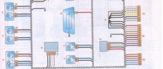
Diagram of the carburetor solenoid valve control system
- 1. Carburetor limit switch
- 2. Ignition coil
- 3. Solenoid valve
- 4. Mounting block
- 5. Ignition relay
- 6. Ignition switch
- 7. Wire harness block connected to the electro-pneumatic valve control unit.
- 8. Solenoid valve control unit
A. The order of conditional numbering of plugs in the control unit
Historical reference
The VAZ 2101 platform was taken as the basis for production. At its core, it was the same rear-wheel drive five-seater sedan car. The VAZ 2105, with its design, practically copied the models of cars produced in Europe in the early 80s, and cost an order of magnitude lower, which predetermined its popularity in Western countries.
Abroad, the car was named Lada Riva and Lada Nova (depending on the country of sale). Under these names he was shown in video advertisements.
The car plant produced several modifications of the VAZ 2105:
- With the VAZ-2105 index, the car was equipped with a 4-speed gearbox. gearbox and 1290 cc carburetor engine. cm (63 hp);
- The VAZ-21050 was equipped with a 5-speed checkpoint;
- The VAZ-21051 was equipped with an engine from the VAZ 2101 (volume 1200 cc, power 58 hp) with a 4-speed. checkpoint;
- The VAZ-21053 was equipped with a VAZ-2103 carburetor engine (volume 1450 cc, power 71 hp);
- The VAZ-21053-20 was equipped with an injection engine from the VAZ-2104 (volume 1450 cc, power 71 hp), which met Euro-2 requirements. It also came with 5 tbsp. Transmission.
For reference: the electrical wiring of the VAZ 21053 was distinguished by a different form of terminals in the engine compartment. This was caused by the installation of an ECM - an electronic engine management system and additional sensors.
Removing the car dashboard
- using a Phillips screwdriver, remove the self-tapping screws that secure the central one;
- console trim, protrusion located at the bottom, remove the protrusion from the bracket;
- Using a nozzle, unscrew the five screws located in the console on the right, remove the screen;
- Disconnect the terminal with the (-) sign from the battery. If there is a radio receiver, you need to remove it, remove the shield from the plug;
- Disconnect the wires coming from the cigarette lighter and remove the cartridge;
- Using a narrow screwdriver, remove the handle from the levers;
- pull the handle towards the heating and fan switches;
- unscrew the two screws above the panel and the two located under it using a screwdriver;
- Unscrew the self-tapping screw with the panel facing it;
- Also unscrew the two self-tapping screws securing the cover;
- disconnect the harness and wire connectors. When installing the panel there is no confusion, the order of their connection should be marked;
- unscrew the bolts;
- the fastenings are two self-tapping screws, the ones that secure the bottom bracket using a size 8 wrench;
- unscrew the fastening screw of the light guide and remove it;
- Also unscrew the self-tapping screws securing the heating unit;
- remove lamp sockets;
- after removing the external parts, remove the decorative insert;
- unscrew all the hydraulic corrector nuts by 21;
- use a key to remove the lamp;
- unscrew which, the screws are attached to the cross member located on the left.
- At the end the panel itself is removed. The panel assembly is accordingly carried out in the reverse order.
Signs of trouble
There are several types of condition of the “five” electrical circuit when car owners have to look for a malfunction:
- The car can't move. In principle, there can be many reasons for this. This could be a breakdown of certain components and mechanisms, or problems in the operation of the electrical circuit.
- The car can be driven, but the electrical equipment is not functioning correctly.
Connection diagram for the instrument panel for the “five”
If you try to start the engine, this does not work, but gasoline flows into the unit without problems, most likely, the problem must be looked for in the circuit:
- As mentioned above, injection versions are more complex in terms of electrical wiring and equipment. As practice shows, in most cases the problem lies precisely in the internal combustion engine control system. For example, if the vehicle system cannot process signals from the regulators and, accordingly, transmit signals to auxiliary mechanisms, most likely the problem is in the circuit.
- If you have a carburetor “five”, then first you need to diagnose the spark plugs, as well as high-voltage circuits. It happens that high-voltage wires become bent or their contacts oxidize, which leads to problems in the operation of the car. In addition, it is advisable to check the functionality of the ignition coil and distributor.
In fact, on any version of the VAZ 2105, be it an injector or a carburetor, one of the main reasons for the incorrect operation of the equipment is contacts. They oxidize or burn, which can result in difficulties in the operation of equipment, in particular, interior lighting or external optics (video author - Max Rublev).
Pinout of the new instrument cluster (with econometer)
Here, everything is the other way around - there is no oil pressure indicator (instead there is an econometer), instead of a brake fluid level lamp there is a suction lamp (or an engine management system lamp on injectors), and instead of a fog lamp lamp there is an oil pressure lamp.
White 6-terminal block X1:
- Gasoline level sensor
- Turn signal indicator lamp
- Battery charge sensor (voltmeter -)
- Gasoline level warning lamp
- Overall plus (+)
- Battery charge sensor (voltmeter +)
White 8 terminal block X2:
- Dimensions indicator lamp
- High beam warning lamp
- Oil pressure warning lamp
- My dash is empty, but there is a terminal in the wiring that goes to the brake fluid level sensor
- Battery charge indicator lamp
- Indicator lamp for the air damper (choke) or engine control unit for injectors
- Empty
- Parking brake warning lamp (handbrake)
Orange 6-terminal block X3:
I decided not to list the colors of the wires here, so as not to completely confuse anyone, because the colors are generally different in all circuits. If you have any questions, I will be happy to help!
Repairing auto parts yourself is a responsible task that should be taken as seriously as possible. Sometimes a faulty spare part takes the driver by surprise, forcing him to spend a lot of time and money searching for a good service station, but there is an alternative solution to the problem; this requires a small amount of knowledge and a set of tools.
When repairing the connection diagram of the VAZ 2105 Zhiguli instrument cluster, you need to be extremely careful and not neglect the little things. To get acquainted with the issue, car enthusiasts often use various Internet portals dedicated to auto parts. Some of them use narrowly focused forums. But, as a rule, only generalized information is provided there, which is known initially. Where can you find a reliable source that offers really useful things? Our portal is open for this 24 hours a day. Online mode allows us to help clients at any time convenient for them. Moreover, a mobile version has been developed that is available to everyone.
A detailed description of such a unit as the connection diagram of the VAZ 2105 Zhiguli instrument cluster has a good structure with thematic headings. In addition, there is always the opportunity to familiarize yourself with the intricacies of installation. There are often situations when a driver is confident in his abilities, but when he gets down to work, questions begin to arise. Thanks to our portal, such moments can be easily avoided. The site is a database that is updated regularly. By using it as a support during repair work, the car enthusiast receives a serious advantage. Each of the articles has reliable support, tested in practice.
In addition to the repair manual, the owner of a personal car will be able to prevent a lot of breakdowns that occur due to the human factor, thanks to the information located on the site. Users are presented with a lot of useful recommendations for proper operation, which will help significantly extend the life of the unit and avoid many negative consequences.
Online support is an excellent and most convenient way to obtain the necessary information. Another significant plus is that articles are written for people. We understand that the reader will do everything with his own hands, and we try to make it as convenient and efficient as possible. Use the resource at any time of the day and find the answer to any question you may have regarding cars.
The VAZ 2105 model first appeared on city streets in 1980 and immediately became extremely popular. The fact is that the design of the car repeated the features of European models of those years: front and rear headlights, aluminum bumpers, and a modern instrument panel.
All this required the designers to rework the usual electrical circuit of the car.
The original diagram published in the article will make it easier for car owners and service station technicians to find faults in the electrical system of a Zhiguli family car.
The VAZ 2105 wiring diagram together with a verification tester will allow you to:
- determine the causes of circuit failure;
- identify which sensor or relay has stopped performing its functions;
- establish a breakdown in the ignition system;
- identify the circuit whose fuse has blown;
- check the on-board voltage supplied by the generator;
- find the cause of failure of incandescent lamps, etc.
Installing the "Start" button
Some Kopek owners tune the ignition system of their cars by installing a “Start” button instead of the standard ignition switch.
But what does such tuning give? The essence of such modifications is to simplify the process of starting the engine. With a button instead of a lock, the driver does not need to poke the key into the lock, trying to get into the cylinder, especially without the habit and without lighting. In addition, you don’t need to carry the ignition key with you and worry about losing it. But this is not the main thing. The main thing is the opportunity to enjoy the process of starting the engine with one press of a button, and also to surprise the passenger with this.
Using this button, you can start the engine without the ignition switch and key.
In automobile stores you can purchase a kit for starting a power unit from a button for about 1,500–2,000 rubles.
A kit for starting an engine with a button can be purchased at auto stores.
But you can save money and assemble an analogue yourself. To do this, you only need a toggle switch with two positions and a button (not recessed), which will fit the size of the ignition switch housing. The simplest connection diagram is shown in the figure.
The toggle switch and button can be installed in any convenient place
Thus, by turning on the toggle switch, we supply voltage to all devices and to the ignition system. By pressing the button, we start the starter. The toggle switch and the button itself, in principle, can be placed anywhere, as long as it is convenient.
As you can see, there is nothing complicated either in the design of the VAZ 2101 ignition switch or in its repair. If it breaks, you can easily repair or replace it.
Why is it needed?
Self-replacement of the ignition switch of a VAZ 2110
As soon as cars appeared, there was no ignition key, and the engine was started using a curved element for the engine, which was quite large and stuck in the front or back of the car. Thus, it turned out that the engine was started manually in the literal sense.
Now this function has been inherited by the starter, which turns the internal combustion engine by the flywheel - a large flat disk with teeth. This disc is located between the engine and the clutch.
This does not happen without the participation of battery power, of course.
The ignition switch is a device that, when turned on, ensures the supply of electric current from the battery to the traction relay. This is a kind of first push to move the vehicle. Therefore, the ignition switch is an important element, and when it breaks, replacement cannot be avoided, and in order to install a new one, you need to remove the old one.
Changing the contact group
Exploded view of the lock
Based on price considerations, replacing one contact group is less expensive:
- All our actions are repeated in principle, as in the case described above with removing the lock, you will have to remove the casing, and so on
- To avoid the widespread problem associated with mixing up contacts, it is recommended to number them before disconnecting (or mark them in some other way)
- This measure will save your nerves and time.
- Some models of locks have a locking ring in their contact group, and here we need an awl to pull it out
- It’s important not to forget to stick it in place later
- Then everything is put back together and screwed to the control column
That's all, all that remains is to finish watching the video and relax and change every part of the lock.
Schematic electrical diagrams, connecting devices and pinouts of connectors
The ignition switch in cars of the VAZ family fails from time to time due to weakening of the contact posts or burning of the contacts inside it. It also happens that the cams of a plastic roller are produced. You can disassemble the lock and clean it, but it’s better to just replace it with a new one, considering that it costs pennies compared to imported locks.
But if connecting the wires together did not result in the starter operating (or it did not turn on the first time), check the solenoid relay on the starter. The contact spots on it may also burn out, which will prevent the circuit from closing normally. Alternatively, you can use a screwdriver to short-circuit the two large terminals on the solenoid relay (before doing this, put the car in neutral and use the handbrake). When closed, the starter should begin to spin vigorously. If this happens, remove and change the solenoid relay. If the starter rotates “sluggishly” when it closes, you will have to remove it and check the condition of the brushes.
The ignition switch is designed not only to start the engine - it performs several functions at once:
- supplies voltage to the vehicle’s on-board network, closing the circuits of the ignition system, lighting, sound alarm, additional devices and instruments;
- at the driver’s command, turns on the starter to start the power plant and turns it off;
- turns off the power to the on-board circuit, preserving the battery charge;
- protects the car from theft by fixing the steering shaft.