27.09.2019
| (Votes: 2, Rating: 4) |
Issues discussed in the material:
- Why are high voltage ignition wires needed?
- What are the causes and signs of malfunction of these wires
- How to check high voltage ignition wires
- How to choose the right high-voltage ignition wires
Among all automotive electrics, high-voltage ignition wires, also called spark plug wires, deserve special attention. They are special in that they can withstand high voltage current, protecting other components and mechanisms of the car from it. Any car owner must know how to check high-voltage ignition wires, because any malfunction of the spark plug electrics can lead to the failure of expensive components.
Why are high voltage ignition wires needed?
High-voltage wires transmit electrical impulses from the ignition coils to the spark plugs and must meet certain requirements:
- high voltage resistance (up to 40 kW);
- minimizing losses during electricity transmission;
- creating minimal interference for radio devices and other electronic equipment;
- sufficient insulation to prevent current leakage;
- preservation of properties in a wide temperature range: the same operation both at -30 in winter and at engine temperatures above +100 degrees Celsius in summer.
To minimize losses, it is recommended to reduce the resistance of high-voltage electrics. Wires with a copper core, which have been used since ancient times, have low resistance. However, this wiring has a significant drawback - it produces strong electromagnetic interference, which has become especially noticeable with the massive introduction of radios, televisions, modern on-board car computers and other devices.
To eliminate this drawback, an additional resistor was added to the high-voltage ignition network to suppress interference. It is built into the distributor rotor, directly into the spark plug or into its cap in different versions. The carbon electrode located in the distributor cap also has resistance.
We recommend
“Why the steering wheel and ignition switch are locked: all the answers” Read more
Today, high-voltage ignition wiring with distributed resistance is most often used to reduce interference. This method is quite effective during verification.
Selection of armored wire
Armored wires are selected depending on the type of ignition. For contact, typical of early VAZ models or old foreign-made cars, low-resistance lines with end resistances of up to 1–1.5 kOhm are used. The same applies to situations where spark plugs with a built-in resistor (R or P series) are used.
Microprocessor ignition, or using purely electronic components, requires high resistance busbars of 1.5–3 kOhm/m. The latter is important due to the high sensitivity of high-tech elements to electromagnetic interference.
When purchasing high-voltage wires, regardless of the seller’s words or the specified characteristics, it is advisable to find out the exact resistance parameters by measuring them with a multimeter. Unfortunately, there are initially low-quality products, or those coming from the dismantling of damaged cars.
Causes and symptoms of malfunction of high-voltage ignition wires
Without checking the high voltage ignition wires, certain problems may arise. The engine will begin to “triple”, its power will drop significantly. In addition, the vehicle's starting system may fail. This malfunction requires immediate elimination, otherwise the entire ignition system may fail, and due to malfunctions in the engine, malfunctions will occur in the mechanical components of the machine.
1. Possible causes of malfunction
Most often, a check shows that the problem lies in the natural wear and tear of the high-voltage ignition wiring. Since it is very close to the engine, it experiences a significant temperature difference, which in winter can exceed 100 degrees Celsius during the day. The quality of the wire insulation decreases over time, cracks appear through which vapors of antifreeze and washer fluid, road reagents, oils and ordinary moisture get inside. If the depth of the crack in the insulation reaches the core, a breakdown of the high-voltage pulse to ground is possible. In this case, the ignition current does not reach the spark plugs.
Often, as a result of the test, it turns out that there was a mechanical impact on the wire. As a rule, this occurs at the junction of the conductor with the contacts of the spark plugs and ignition coils. When installing high-voltage wiring, it is important to install it correctly with the obligatory use of polyester vinyl crimp clamps to protect it from excessive mechanical stress.
Finally, the test may show that high-voltage electrical equipment has been damaged due to exceeding the voltage limit. This can happen when the ignition coil breaks down in the primary winding.
2. Signs of malfunction
A possible malfunction of high-voltage wiring can manifest itself with the following symptoms:
- starting the engine is difficult, especially in rainy weather;
- the engine periodically “troubles” while driving, this is also observed when idling and during a “cold” start;
- strong interference appeared in the radio receiver and amplifier, and in other amplification equipment;
- fuel consumption has increased noticeably;
- the wires changed color, breakdowns and leaks appeared in the form of dark spots.
Checking with an oscilloscope
This is the most accurate method of checking, but its use requires you to have the device itself and knowledge in deciphering the values. If you have this, you can check this way, otherwise the previous methods of checking armored vehicles are enough for you to conclude about replacement or repair.
Procedure:
- attach the inductive and capacitive sensor of the device to the wires;
- turn on the oscilloscope;
- start the engine;
- watch the readings.
A professional will immediately understand the presence or absence of a problem using an oscillogram. Look at the photo of the graph; if yours is similar or identical, then the wire is broken and requires replacement.
The spark line must be smooth and without noise, otherwise the wire is broken or the spark plug is faulty. If the line reaches the maximum value of the coil, this is a complete break in the wiring.
Studying the operation of an oscilloscope is quite useful, since in the future you can diagnose the operation of the entire ignition system and electronic sensors, for example, the operation of the crankshaft position sensor.
How to check high voltage ignition wires
Checking high-voltage ignition wires for breakdown is carried out in one of three ways.
- Visual inspection
Visual inspection is the easiest way to check and detect damage to the insulating layer of high-voltage wiring. During this inspection, you need to make sure that there are no cracks, cuts or noticeable abrasions on the insulation surface.A breakdown can be determined visually by sparking. To do this, in the dark, just open the hood of the car, start the engine and turn off the lights. An insulation breakdown will be noticeable to the naked eye by sparks running through the wiring.
We recommend
“What is a catalyst in a car, and what functions does it perform?” Read more
- Checking in the “old-fashioned” way
Often it is not possible to visually determine that the high-voltage ignition wire is faulty. In such cases, the old proven method is used, which consists of the following steps. The engine is started and left to idle. Next, the contacts are removed one by one from the spark plugs and then put back on. All operations must be performed with rubber gloves, without touching the car body with your body. The conductor is faulty if, when it is disconnected from the spark plug, engine operation does not change. - Testing with a wire
The next method is to use a piece of wire stripped at both ends. The check is carried out at night with the engine running. One end of the segment is connected to the car body (“ground”), the other end must be driven along the high-voltage ignition wiring. If a spark appears when carrying out insulation, there is a breakdown in this place. This way, not only the insulation is checked, but also the plastic protective caps. - Checking high-voltage ignition wires with a multimeter
Car owners usually measure voltage with a multimeter, but the same device can also determine resistance, which is very useful when checking.For measurement, the high-voltage ignition wires are first disconnected or completely removed. The multimeter needs to be switched to resistance measurement mode, then the probes of the device need to touch the two ends of one wire. The device will show the measured value.
Normally, the resistance of the spark plug wiring should be from 3.5 to 10 kOhm. Accurate data must be indicated on the insulating layer. The resistance value determined by the test will depend on the material of the core, the length of the wire, the insulation used, the presence of microscopic damage in it, etc.
If, as a result of the test, one conductor turns out to be faulty, the rest will soon fail. Therefore, replacing the high-voltage ignition wiring is done as a set, rather than as separate wires. These products most likely will not be sold to you separately.
Carburetor Feature
On a carburetor engine, you can unscrew the spark plug and place it on the cylinder head together with the armored wire. Next, crank the crankshaft a little with the starter and watch for a spark. The engine is a mass, so a strong spark must be produced. If there is little or no spark, then the problem is in the wire.
But, the method will work if all the candles are in excellent condition. After checking, you can additionally inspect the wire visually or “pierce” it with a multimeter.
We also recommend that owners of carburetor internal combustion engines initially check the central high-voltage wire going to the distributor. This will help identify the problem if the engine does not start or the power has dropped very much. Perhaps the central one does not supply enough voltage to the others through the distributor.
A similar procedure cannot be carried out with an injection engine, because the electronic switch and engine control unit will fail.
How to make temporary wire repairs
Let's say a check of the high-voltage ignition wires reveals damage to the wiring, and the nearest service station is far away. What to do in this case? First you need to accurately identify the damaged area.
Next, on both sides of this area, the cores are stripped using a knife. The stripped areas need to be connected, creating an electrical circuit, for which any conductor is suitable, preferably copper-based. The connection is made by ordinary twisting.
The main difficulty here is the creation of a high-quality insulating layer. A layer of ordinary electrical tape can withstand voltages of up to 6 kW. In this case, reliable insulation is required for voltages reaching 40 kW. Therefore, to provide this protection, you will need at least 8-10 layers of electrical tape without taking into account the fact that moisture can penetrate between the layers. The tape itself must be of high quality. To ensure that the insulation is also of high quality, it is worth covering the area to be repaired in a plastic box. Before repairing and checking, all wiring must be thoroughly cleaned of dirt and traces of oil.
What else can I recommend?
In addition to the listed components, there are also such as Bautler, xopc.
Products from Bautler, which have proven themselves to be highly reliable and efficient among consumers
Bautler uses rubber for the insulating layer, which causes a slight thickening of the product, but allows the ignition parts to work in more difficult conditions.
We also can’t help but say something about xopc’s products. It has been present in the automotive market since 1995. Experts note that today xopc is one of the largest manufacturers of silicone cables in the Russian Federation. To manufacture its products, xopc uses imported raw materials. The production process is carefully controlled at all stages of production.
I would also like to say a few words about armored wires for car ignition systems. The first samples of such parts began to be used on vehicles intended for the Armed Forces. They were subjected to additional shielding with metal braiding to protect radio-electronic devices from interference. Currently, such armored wires can only be found on older cars. The achievements of the developers make it possible to produce armored wires without visible metal shielding.
In conclusion, I would like to recommend that car enthusiasts, if they need to replace armored wires or high-voltage wires, first of all follow the vehicle’s operating instructions. You can choose an elephant or another brand, but this should not be to the detriment of the power unit.
Which high-voltage ignition wires are better: reviews from car enthusiasts
One of the car enthusiasts under the nickname TANJA-NEV shares her husband’s experience: “My husband bought a set of Tesla ignition wires on the automobile market. This is a thick cardboard box on which information about these products is written. The box described both the technical characteristics and the advantages of these particular ignition wires. Country of origin: Czech Republic, Blatna. Inside the box, right on the back of the lid, the date of manufacture of this product is indicated.
The conductors of this Czech kit have different lengths. During replacement and testing, a suitable new wire is taken and installed in place of the old one. The new conductor must be secured tightly to both the spark plug and the distributor. The wires, of which there are 5 pieces in the set, have rubber tips - it is by these that you need to hold the products during the installation process. External inspection of the kit showed its acceptable quality.
In addition, a small instruction is attached, which also describes in Russian the steps for correct replacement. Everything is quite simple. It is important to change the conductors one at a time and on a cold engine.
The wiring was replaced by my husband himself about six months ago, and to date the inspection has not revealed any problems. The products retain flexibility and elasticity, but the engine has added more power.”
The user VIK_91 had standard high-voltage wires in his car, which wore out over time, which manifested itself in the form of poor acceleration of the car and increased vibration when driving. The author writes: “At that time, the car was used by my father, who replaced the original wiring with SEIWA products. This gave some improvements in performance. While replacing the spark plugs, I encountered the problem of removing the spark plug wiring - it came off, and the contacts remained inside the spark plugs. As a result, I had to remove the contacts with tweezers and quickly restore the wires themselves. The restored electrics did not work for long, and they were checked and replaced not long ago. My choice fell on products from Masuma, which worked well in my previous car. They are quite flexible, provide reliable contact and are tightly connected to the candlestick.”
Purpose and service life
The work performed by the wires becomes clear from the name. During engine operation, high-voltage current is supplied to the spark plugs for the purpose of timely spark formation in the cylinders. The generated voltage reaches 50 kV. In the process of transmitting current, the side process of heating the wiring is almost inevitable. By using insulation, the car body and components are simultaneously protected from electric leakage.
The maintenance schedule for almost no model does not establish a service interval for replacing wires. Usually the installation of new spark plugs is normal. Most often, this indicator is set at 30 thousand km. When servicing the car privately and normal engine operation, the spark plugs work up to 50 thousand km. Typically, high-voltage ignition wires are visually inspected at this very moment.
Briefly about the structure of conductors
Previously, traditional explosive wires with a copper stranded core (in jargon - armored wires) were used to supply a discharge from the coil to the spark plugs. The disadvantage of such products is the gradual breaking of thin wires due to low elasticity. In modern cars, manufacturers install flexible cables with a non-metallic core made of carbon-impregnated fiberglass. The current-carrying part is wrapped in several auxiliary shells:
- polymer shielding layer;
- silicone-based internal insulation;
- frame in the form of a braid made of durable synthetics;
- external silicone insulation.
Old products with copper conductors had practically zero resistance, causing the radio installed on the car to “wheeze” from interference. Today's high-voltage wires have increased resistance, allowing them to screen out interference.
To connect to the spark plug “cradle” contact, the carbon core is brought out beyond the insulation and bent in the opposite direction. From the outside, the core is crimped with a copper terminal placed on the spark plug contact. The connection is protected from above by a dense dielectric cap. The second end of the conductor is connected to the ignition coil in a similar way.
An important advantage of the new high-voltage armored wires is elasticity and flexibility. Thanks to these qualities, the product lasts much longer than its copper predecessors. But sooner or later there comes a time when the carbon-silicon explosive wires wear out and begin to “mope.”
Total current measurement
Measuring the total current is necessary to determine overloads in the system; it allows you to understand whether the installed equipment, and especially the conductors used, correspond to the operating mode of the vehicle’s on-board electrical network. Indeed, in many cases, it is problems with power mismatches that serve as a prerequisite for the failure of individual parts, insulation breakdown and other electronic malfunctions.
To measure the total current under load, connect the multimeter to the battery circuit and set it to high-ampere mode (A 100). Turning on the ignition, load the network using headlights, running lights, heating systems, radio, and other available electronics. The electricity consumption of the starter is usually not taken into account since it is only turned on for a short time. The multimeter readings will be called the maximum (“peak”) current value in the car’s on-board network.
The principle of connecting consumers to the vehicle’s on-board network
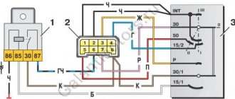
Electrical diagram for connecting headlights
The flow of electric current through a conductor is only possible if the electrical circuit is closed in one way or another. That is, in the case of “normal” consumption of electricity, the circuit: battery terminal “plus” – consumer – terminal “minus” should have no breaks. Of course, this is the most simplified circuit diagram. In a car, most consumers are connected using a more complex circuit, which makes it difficult for an untrained person to understand it. In order not to search for faults blindly, let us take for clarity the diagram presented in the figure above. As you can see, the lamps and terminal 85 of the relay have a common “minus” - on a car it is often connected to the body - “ground”. The positive wire is “broken” by the switch. When the contacts of the switch are closed, the current passes through the relay coil connected to contacts 86 and 85. The coil, thanks to the electromagnetic field, closes contacts 87 and 30 and the current passes through the lamps.
Before checking current leakage, set the multimeter to ammeter mode
Almost all electrical appliances in a car operate in a similar way - only, as a rule, their circuits are opened by another switch - the ignition switch, and a fuse “cuts” into the positive wire. For convenience, relays and fuses are combined into a mounting block (or even two). All this is said here so that you do not get confused at the sight of the mass of wiring harnesses and so that, having mentally divided the many connected circuits into small circuits, you search for the location of the current leak purposefully, without missing anything. Naturally, some devices are combined into common networks, but, nevertheless, it is easy to imagine many of them as one consumer - but somewhat “extended” in space. The causes of current leakage in a car may be unwanted “connections” of various circuits either to each other or to the “ground” of the car due to damaged wire insulation or due to dirt forming “bridges” for current.
General information
You don't need to be a professional electrician to find a wire break. It is enough to have a measuring device - a multimeter. A multimeter is a multifunctional measuring instrument with its own voltage source. The device can measure the voltage in the circuit, the magnitude of the current and the resistance value. Many multimeters are used to test the continuity of a connection in a circuit.
If a connection is found, then if there is a built-in speaker, the device emits a sound signal. This is where the term “call” comes from. The device rings if there is a connection. A multimeter can also indicate that there is no connection between elements and helps determine a short circuit. Using the tester, all kinds of radio components are checked: resistors, transistors, diodes, relays, capacitors, and so on.
Conductor continuity is based on Ohm's law for a section of an electrical circuit. Ohm's law states that the resistance of an element is equal to the ratio of the applied voltage to the magnitude of the current in a section of the electrical network. Resistance is measured in Ohms. A resistance of one Ohm indicates that a current equal to one Ampere flows through the conductor at a given voltage of one Volt. Based on the calculated data on resistance, conclusions are drawn about the results of the call.
That is, a certain voltage is set on the multimeter, and the current value is determined using the instrument scale and the resistance is calculated. In other words, the multimeter is a voltage source and an ammeter to measure the resulting current.
