The onboard voltage of the VAZ 2114 is exactly 12V, this is explained by safety criteria. Increased voltage cannot be used in a car due to the high risk of fire. However, in a car there is a voltage that exceeds the permissible values by many tens of times; this is the voltage that produces a spark, going from the coil to the spark plug on the spark plug. To transmit such high voltage to the VAZ 2114, special armored wires (high-voltage wires) are used.
This article will focus specifically on these wires, describing in detail their purpose, replacement time, connection diagram and, of course, symptoms of a malfunction.
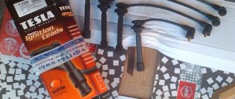
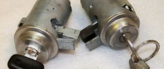
High-voltage wires VAZ 2115
Automotive high-voltage (HV) wires play an important role for internal combustion engines, since they help transmit high current from the ignition coil to the spark plugs. The serviceability and efficiency of the wires determines the timeliness and intensity of ignition of the fuel-air mixture, and therefore the correct and uninterrupted operation of the engine. Despite their simplicity, wires have many different “sores” and can cause a lot of troubles to their owner, which in one way or another will affect his nerves and pocket.
Connection
The order of connecting high-voltage wires must be strictly sequential, since each cylinder of the engine corresponds to a specific socket on the ignition module. Considering that there is a numbering of the sockets on the ignition module body, the risk of confusing anything is minimal.
The procedure for connecting high-voltage wires of the VAZ 2114 injection type depends on the year of manufacture of your car. Fourteen cars before 2004 had 4-pin ignition modules installed, and cars after 2004 had 3-pin coils.
The connection diagram for VAZ 2114 high-voltage wires to the ignition module (until 2004) is as follows:
Connection diagram for VAZ-2114 with ignition coils (after 2004):
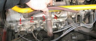
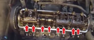
In the pictures you can see the numbers of the landing slots. Each number must have a corresponding cylinder connected to it (cylinder numbering is counted from left to right).
To correctly install high-voltage wires on the VAZ 2114, follow the following algorithm of actions:
— Turn off the ignition. Open the hood and remove the power terminals from the battery;
— We remove the old GDPs from the mounting sockets on the module and cylinders;
— We remember the location of the high-voltage wires of the VAZ 2114 and connect new GDPs according to the diagram. Before replacing, it would not be amiss to draw this very diagram by hand on paper so as not to confuse anything;
— We connect power to the battery and, to check whether we did everything correctly, start the engine.
When installing the wiring, do not try to connect individual air intakes to each other with plastic clamps; to do this, you must use the comb holder that comes with them. A thin clamp can easily wear through the insulating coating. Also make sure that the GDP does not bend.
Connecting armored wires on VAZ 2115 and 2113 is carried out in a similar way.
Instructions: replacing the brake master cylinder.
How to remove high-voltage wires?
Turn off the ignition. Open the hood. Pull out the wires from the ignition module and from the engine.
How to connect high voltage wires?
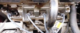
The BB wires must be connected in a certain order. Each wire goes to a specific cylinder and to a specific connector in the ignition module (ignition coil). There are markings both on the wires and on the ignition module. But without removing the module, the markings cannot be seen, so see the photo below.
Connection diagram for high-voltage wires:
Cylinder numbering from left to right. Ignition module numbering: first cylinder - lower left compartment of the ignition module
Second cylinder - upper left compartment
The third cylinder is the upper right,
The fourth cylinder is the lower right compartment of the ignition module.
Location
Incorrect installation and location of high-voltage wires can lead to a spark jumping from wire to wire or to ground, which, in turn, can lead to misfires and a decrease in the crankshaft speed when the car is moving at high speed.
Therefore, install the high voltage wires properly as shown in the pictures above.
Disconnect the high-voltage wires from the spark plugs and ignition coils. Clean and check the integrity of the insulation of high-voltage wires. Check the internal contact surfaces of high-voltage wires for corrosion or carbon deposits.
Use an ohmmeter to measure the resistance of the high-voltage wires.
How to connect wires correctly
When replacing high-voltage conductors, they are first connected to the ignition distributor. The distributor cover is convenient in that it is always installed in one position. There is a special mark on it, thanks to which it will not be difficult to place the part in place. Before connecting the wires, inspect the cover. It must be intact, since if cracks appear, the performance of this unit is not guaranteed.
The mark on the distributor cover is located next to the wire socket of the first cylinder. The firing order of the cylinders is slightly out of order (1-3-4-2) due to the ignition slider. It moves around the circle (distributor) counterclockwise. It is precisely by this principle of movement of the slider that it is easy to remember the order of the wires. They need to be connected to carburetor and injection VAZ-2109 according to the same principle. On the distributor cover, connect the wires according to the principle of movement of the slider, this is the only way you can set the ignition correctly:
- the socket of the first cylinder is located at the mark;
- the third one is connected at the very bottom;
- on the same line with the socket of the first, there is a place for the wire to the 4th cylinder;
- at the top point the second cylinder is connected.
On the engine itself, the cylinder numbering goes from the location of the timing belt to the starter, that is, from left to right. The fourth cylinder is closest to the starter, and the first is closest to the timing belt. When connecting, it is important to look at which socket of the distributor cover the wire comes from, if you confuse their location, the car will not start.
If you have connected the wires correctly, but the car still does not start, then the problem may be in them. Check high-voltage conductors for integrity. If you haven't changed them in a while, it's worth buying a new set. The peculiarity of these wires is that over time microcracks can form on their surface. They lead to a lack of spark when the ignition distribution system is working. Moisture and dust get into these cracks, which damages the wire from the inside, although it appears intact from the outside.
Signs of faulty armored wires of the VAZ 2114
The main symptoms of a malfunction of the VAZ-2114 ignition module
The main symptoms of a malfunction of the VAZ 2114 armored wires are:
- Difficulty starting the engine;
- Unstable operation of the engine in idle mode;
- Increased hydrocarbon content in emissions;
- Radio interference, which can lead to malfunction of the multimedia system, electronic control unit and other devices
Therefore, in order to avoid lowering your ranking in search engines, a link to the source is required.
As a rule, when there is severe wear on the wire insulation, many microcracks appear, due to which current leakage occurs. As a result, the wire is not able to transmit to the spark plug a current that is sufficient in magnitude for its normal operation. This significantly increases the spark generation time and interferes with the correct operation of the engine cylinders.
Location of the ignition module of the old VAZ 2114
Quite often there are cases when wires are damaged as a result of contact with any engine elements. Situations of loss of cap tightness are also possible, and as a result - oxidation of contacts and current leakage. Regular cleaning of contacts is a mandatory procedure, especially when operating a vehicle in difficult climatic conditions.
Why do idle speeds fluctuate on carburetor engines?
Tuning VAZ 2114 tuning Lada 2114 with your own hands, photo in addition
VAZ-2114 “Samara” with a carburetor internal combustion engine is also not immune to this problem. This happens, fortunately, not every day, but still. The main reason for this is an incorrectly adjusted or faulty carburetor itself. Also, floating speed can be caused by air leaks or a faulty XX solenoid valve. In addition, it is worth checking the air filter for deposits.
But most often, floating speeds arise precisely because of incorrect carburetor adjustment. In this case, you should adjust it by correctly rotating the fuel quality and quantity screws.
As for the solenoid valve, it can be diagnosed without removing the power wire from it. With the ignition on, it is enough to touch the contact on the valve with the cord - a characteristic click should soon appear. If it is not there, you can try to touch the contact with the wire that is connected to the positive terminal on the battery. If after this you do not hear a click, then most likely the valve has malfunctioned. To repair it, you need to unscrew it and clean the nozzle.
So, we found out why the speed on the VAZ-2114 fluctuates and how to fix this problem depending on the type of fault.
The five-door hatchback VAZ 2114 is a restyled model of the famous “nine”, which rolled off the assembly line of the car plant from 2003 to 2013. At various times, the manufacturer installed on the car power plants with carburetor or distributed fuel injection (injector) of its own making, and since 2007 the car has been equipped with an electronic engine control system. Note that all these engines have one common and very significant drawback - when they switch to idle mode, their crankshaft speed suddenly begins to “float”.
Firing order
The procedure for tightening the cylinder head of a VAZ 2109
The cylinders in a car do not work chaotically, because for stable operation of the engine and alternate execution of all four strokes, their strict synchronization is required.
So there is a special order of operation of the cylinders of the VAZ 2114, thanks to which each of them at one point in time performs any of 4 strokes, namely:
- Injection of a mixture of fuel and air that fills the entire volume of the cylinder.
- Compression of the working mixture due to the upward movement of the piston.
- The combustion of the working mixture and the expansion of the resulting gases pushes the piston in the opposite direction, thereby driving the connecting rod and crankshaft.
- The release of exhaust gases from the cylinder with their further discharge into the exhaust system.
It is worth noting that on cars of different brands and even models, the engine may have a different operating diagram, but the order of operation of the VAZ 2114 injector cylinders always looks like this: 1-3-4-2. According to this diagram, the high-voltage wires should be connected.
For greater convenience, the cylinders are numbered accordingly, starting from the front cover of the engine.
The principle of operation of a four-stroke power plant
You can understand why it is important to connect high-voltage wires correctly if you study the principle of operation of the power plant. The carburetor or injector of the VAZ-2109 operates on approximately the same principle, since both power plants are four-stroke.
- First, the cylinder volume is filled with the fuel mixture and exhaust gases. This process is called "inlet".
- The engine then goes into compression. With it, the valves are closed, and the crankshaft and connecting rod move the piston upward. The mixture of fuel and air is transferred to the combustion chamber.
- During the expansion stage, the ignition is switched on and a spark appears. It ignites the fuel mixture, resulting in the formation of gases. They put pressure on the piston, causing it to move down. This force is transmitted through the connecting rod to the crankshaft.
- The process is completed by the “release” of exhaust gases through the exhaust system.
In order for the engine to operate smoothly and without jerking, the processes must take place in a certain order. This, first of all, concerns the order in which the cylinders are put into operation.
Armored wires and their connections
Checking the ignition module on a VAZ 2114: a multimeter and test to help
Having found out how the location of the VAZ 2114 cylinders affects their connection, it is worth talking about the high-voltage wires with which this is done.
These wires themselves are quite different from ordinary electrical wires - they have an increased layer of insulation, protective shielding, as well as metal connecting tips and protective caps made of heat-resistant plastic. The main purpose of these wires is to transmit a high-voltage pulse from the ignition unit to the cylinders (it is this pulse that allows the spark plugs to ignite the working mixture).
Armored wires VAZ 2114
The connection of armored wires should be made taking into account the ignition order of the VAZ 2114 injector and the numbering of the cylinders (this was mentioned above). For greater convenience, you should be guided by the numbering present on the ignition module - just connect socket number 1 to the corresponding cylinder, socket number 2 to cylinder number 2, etc. It is extremely difficult to make any mistake here.
Operational repair
p, blockquote 36,0,0,0,0 —>
What to do if the spark plug wire breaks off or breaks far from populated areas.
p, blockquote 37,0,0,0,0 —>
First, using the methods outlined in paragraph 2, find the location of the damage, breakdown or break. Then, using a knife, strip the conductive wires on both sides of the damaged area.
p, blockquote 38,0,0,0,0 —>
The next stage is an electrical connection using any conductor (wire), preferably copper. It can be produced by ordinary twisting.
p, blockquote 39,0,0,1,0 —>
The most difficult thing is to perform high-quality insulation. Conventional electrical tape has a breakdown voltage of 2,000 to 6,000 Volts. It is necessary to provide insulation for voltages up to 40,000 Volts.
p, blockquote 40,0,0,0,0 —>
It is easy to calculate that in this case it is necessary to lay at least eight to ten layers of electrical tape. And this does not take into account the penetration of moisture between the layers. The insulating tape must be of high quality. To improve the quality of insulation, you can place the repair site in a plastic box.
p, blockquote 41,0,0,0,0 —>
Before repairs, high-voltage wires should be thoroughly cleaned of dirt and oil stains.
p, blockquote 42,0,0,0,0 —> adsp-pro-2 —>
Wiring check
Checking high-voltage ignition wires begins with a simple diagnosis, because all of the above symptoms of problems may indicate a breakdown of other parts of the engine system or something else. For a simple check it is better to wait until dark. Then you need to expose a small section of the wire on one side and the other and close one end to the body of the car or battery, and the second is needed for maneuver: we move it along the wiring joints, plugs, and so on. When there is a hole there will be a spark immediately. The result is obvious - replacement is required. But this method is primary; it concerns direct current leakage, which is not always the reason for the non-operating state of high-voltage devices. In the case of voltage, such a number will not work.
To measure it, you need to know what resistance the high-voltage wires should have. After all, each wire from a specific manufacturer has its own resistance, technical characteristics and dimensions:
1) Tesla - 6 kOhm, it is often counterfeited, then you can squeeze out as much as 8 kOhm
2) Elephant - from 4 to 7 kOhm
3) ProSport tends to zero
4) Kargen - 0.9 kOhm
Checking high-voltage ignition wires with a multimeter
For measuring work, you need a simple multimeter, which we switch to ohmmeter mode. We measure one wire at a time, removing one by one from the cylinders from left to right and from the coil itself. The procedure is simple:
- make sure the car is turned off
- remove the end of the wire from the fastener on the cylinder
- remove the opposite end from the ignition coil mounting
- you need to connect both ends to the multimeter
- read the readings
- write them down so as not to forget
- We do this three more times with the remaining wires
Normal resistance is numbers in the range from 3.4 to 9.8 kOhm. Of course, all this depends on the manufacturer; this parameter is printed on the rubber skin of the wire. If you have a difference with the permissible value, which varies from 2 to 4 kOhm, this is normal. But no more! If more, then the wires are not suitable for driving, they need to be changed.
We always replace wires as a set! Even if one has fallen into disrepair, and the rest are in good technical condition.
That's basically it. Now you should replace the old wires with the purchased new ones.
The main task of high-voltage wires is to transmit a current pulse from the ignition coil to the spark plug.
Timely and guaranteed ignition of the fuel in the cylinder depends on the quality of current transmission, which entails normal, correct operation of the engine.
For various reasons, high-voltage (HV) wires may not conduct at all or conduct only a small part of the current pulse from the ignition to the spark plug.
The main reasons for the malfunction of explosive wires are the following:
- core rupture;
- current leakage (breakdown through insulation);
- resistance is higher than normal;
- poor contact with the spark plug;
- rupture of the conductor.
With faulty explosive wires, the engine runs intermittently and produces extraneous vibrations, because In some cylinder the combustion of the mixture occurs with a delay.
Replacement
Changing the resistor is easy. But for this you will have to take several steps.
- Make sure that the problems with the heater on the VAZ-2114 are related precisely to a faulty resistor.
- On the left is your car's dashboard console trim. Remove it to find the failed element.
- Wires are connected to it. They must be removed carefully so as not to damage them. It will not be superfluous to check the integrity of the wiring.
- Unscrew the fastening element. The resistor is held in place by a regular screw, so take a screwdriver with you.
- Remove the old element and check its operation.
- A regular multimeter is suitable for checking. Its presence in the garage or in the car greatly helps car owners when diagnosing and repairing their car. Check the resistor for breaks.
- If there are breaks, then the resistor is unsuitable for use. You need to buy a similar new one and install it in place of the old element.
- Reassemble in reverse order.
There is nothing complicated about the work, so you can do it yourself. This will save you time and money on visiting a service station.
Important! If problems arise in the heating system of the VAZ-2114 regarding the fan, be sure to check the fuse. Always start looking for the causes of malfunctions with the simplest ones, gradually moving towards complex potential causes of breakdowns
It is quite simple to determine that the cause of the heating failure was not a resistor, but a fuse. It is marked F7 and is responsible not only for the heater fan, but also for the headlight washer motor, glove compartment lighting, cigarette lighter and heated rear window. If these components do not work, the problem can be solved by simply replacing the fuse.
If a resistor failed on your car, be sure to write how you dealt with the problem and how difficult it was to change the element. Share your impressions, leave comments and ask questions. We will definitely answer them.
#1 Modeler
There is NEVER time to do a good job. time for rework
Garage workers
3,348 messages
Bon Voyage! To everyone who walks the trails, Bon voyage! And Mersam and KamAZ. Driver, Bon Voyage!
How to check high-voltage armored ignition wires yourself
High-voltage automotive armored wires are a fairly simple element of the ignition system. In this case, the high-voltage wire performs the most important function in the operation of this system. Using high-voltage automotive wires from the ignition coil, electric current is transmitted to the spark plugs to form a spark and timely ignite the fuel-air mixture in the engine cylinders.
The efficiency of ignition of the mixture directly depends on the quality of the high-voltage wires, which means stable engine operation in different modes. A malfunction of the high-voltage ignition wire or several wires can lead to engine stalling, increased fuel consumption, loss of power, etc. The simplicity of the design and location of automobile armored wires allows you to accurately and quickly independently check them with your own hands.
Common malfunctions of high-voltage armored wires
Failure of a high-voltage wire is accompanied by symptoms that are similar to malfunctions during spark plug operation. Often the engine starts to run unstably, jerks when you press the gas pedal, and idles at idle. The electric current may not be supplied to the spark plug at all or may not reach the spark plug completely. In the second case, there is usually a breakdown of the high-voltage ignition wire.
If the ignition armored wire is pierced, then the engine begins to work with noticeable interruptions. The main reasons for the failure of high-voltage automotive wires are:
- malfunction of the high-voltage wire contacts at the junction with the spark plugs or ignition coil;
- The conductor of the pulse supply wire is damaged;
- destruction of the insulation of a high-voltage automotive ignition wire, which leads to current breakdown and leaks;
- increased resistance of high-voltage armored wires;
In the event that a break occurs in the main core, then a spark is formed inside the high-voltage wire at the site of such a break. The formation of an electrical discharge between the two ends of a high-voltage armored wire broken under the insulation leads to a voltage drop and causes an unwanted electromagnetic pulse. Such an impulse has a negative impact on the automotive sensors of the electronic engine control system (ECM), and the correctness of their readings is disrupted.
As a result, it is the damaged high-voltage wire that causes vibrations and malfunctions in the internal combustion engine, since ignition in the cylinder occurs untimely, with skips and delays. The synchronous operation of the cylinders is disrupted, the engine begins to trip and vibrate at idle, as well as under load.
In some cases, when the cylinder fails completely, fuel consumption may noticeably increase and the color of the exhaust may change. This happens due to unburnt fuel entering the exhaust system from the combustion chamber.
Diagnosis of stove malfunctions
The design of the stove is quite simple. It would seem that there is nothing to break here. The heater cannot break down completely, since its design consists of components independent from each other. However, some elements can fail quite often. These include:
- radiator;
- tap;
- pipes;
- resistor;
- mode switch.
Heater radiator malfunctions
The main reasons for the failure of the stove radiator:
- clogging;
- the appearance of a leak (depressurization).
In the first case, deposits accumulate on the inner walls of the radiator tubes. They can form as a result of:
- long-term operation of the radiator;
- use of low-quality coolant;
- getting dirt, friction products, water, etc. into the cooling system.
As a result, the circulation of antifreeze in the heater radiator is disrupted or completely stopped, and the air entering the cabin does not have time to heat up normally. In winter, it will be cold inside the car, and defrosting the windshield will become a real problem.
A leak in the radiator can appear as a result of corrosion and drying out. Coolant leaking from the heater usually forms a puddle on the floor under the panel on the passenger side. In addition, a characteristic odor will appear in the cabin, and an oily coating will form on the windshield due to evaporation of the coolant, reducing the driver’s visibility. The latter is especially true when driving against the sun or at night, when oncoming traffic is moving with its headlights on.
Stove tap leaking
The stove valve may fail for two reasons:
- souring of the locking mechanism;
- drying out of the device casing.
If the stove has not been used for a long time, the tap may become sour. In this case, when trying to open the tap, you should not use much force, as you can damage the tap itself or break the control cable.
When the housing dries out, the leak may not be immediately noticeable. But after some time, signs similar to those of a radiator leak will appear (a puddle of coolant on the floor, a pungent odor in the cabin, an oily coating on the windshield).
If the heater valve is faulty, coolant begins to leak into the cabin.
Wear of pipes
Antifreeze from the heater radiator may begin to leak through the inlet and outlet pipes as a result of their wear under the influence of chemically active substances included in the coolant and high temperature. In addition, the pipes can be damaged if the clamps that ensure the tightness of the connections are over-tightened.
There are a total of four pipes in the heating system of the VAZ 2113–15 - two in the engine compartment, connecting the engine to the tap, and two in the cabin, going from the tap to the heater radiator. Coolant leakage can occur in different ways. In one case, the antifreeze will flow onto the engine protection and onto the street, in the other - into the car interior. In any case, it will appear as:
- drop in coolant level in the expansion tank;
- puddles forming under the car or in the cabin;
- the appearance of an unpleasant odor in the cabin.
Resistor failure
The stove resistor consists of two windings and serves to change the resistance of the electric current supplied to the fan. The fan motor can operate in three modes, which can be changed using a switch.
In the third mode, the fan is supplied with a voltage equal to the voltage of the on-board network, and it operates at full power. When the second mode is turned on, the voltage decreases due to one of the windings, the resistance of which increases to approximately 0.2 Ohms. The fan begins to rotate noticeably slower. And finally, in the first mode, the resistance of the windings increases to 0.8 Ohms, and the power of the electric motor is reduced to a minimum.
The main sign of resistor failure is the fan operating only in the third mode. The reason for this is the burnout of one or both windings.
If the resistor fails, the stove operates in only one mode
Switch failure
The cause of a non-working interior heater can only be determined after checking each of its elements. Sometimes the stove mode switch itself may fail. This occurs quite rarely as a result of oxidation or destruction of its contacts.
Use the switch to change the fan speed
Signs of faulty wires
There can be many different signs of faulty high-voltage wires, but there are several signs that, once detected, require the wires to be replaced.
Signs:
The car jerks when you press the gas pedal. This is due to the fact that with a higher load the engine needs a large amount of fuel and its timely combustion, but since the wires are not able to give a spark at the right time, the car begins to twitch.
When starting the car, one or more cylinders may not fire. This is due to the fact that when a spark is transmitted, it breaks through to the housing due to breakdown of the insulation.
To check the wires in more detail, you need to remove them from the car and carefully inspect them.
The wires should not contain:
- Gusts;
- Zadirov;
- Insulation breakdowns;
- Cracks in the plastic case;
Rupture of the protective cap of the GDP
If such problems are found on the wires of your car, then they need to be replaced.
Checking for correct installation
If the order is followed without errors in the ignition of the 402 engine, then the next task will be to check the power plant while the car is moving:
- We go out onto the highway and, when driving 60 km/h, turn on fourth gear. We are accelerating. The appearance of short-term detonation knocks indicates that the ignition is installed correctly.
- Prolonged detonation knocks are confirmation of incorrect setting of the advance angle.
In this case, you should reduce it with an octane corrector, moving it to one notch. If detonation cannot be heard at all, then the advanced ignition angle of the fuel mixture should be increased. And check again for correct installation by accelerating the car to 60 km/h and shifting to fourth gear.
DIY wires — Lada 2114, 1.6 l., 2012 on DRIVE2
The drive is full of topics with measurements of the resistance of high-voltage wires, some reaching 6 kOhm. So, closer to the point. We will need old high-voltage wires, namely the tips from them, silicone wires from ZIL 130 or GAZ 53, they have a copper core and as we know, copper does not provide resistance. We disassemble the old wires, throw them away, cut pieces from new wires and crimp them. For me, the most difficult thing was removing the silicone protection of the tips.
On the left is a Lada original part, on the right is a Zil 130
PS1) A set of ZIL 130 wires costs 750 rubles, but it’s easily enough for 2 sets, you can sell it to someone) in total, new high-voltage wires cost 350 rubles instead of 1500 rubles 2) It feels like, honestly, I don’t know, it started up better, but not much at idle it began to dangle in around 880-900 rpm, before that 860-910 despite the fact that my car has an electric pedal (E-gas) 3) There is no interference for those who will now rub me in about resistors and interference, catch the sign. For those who are not very clear on the sign fumbles - ALL CANDLES NOW COMES WITH A BUILT-IN RESISTOR
Good luck everyone !
UPD: In general, guys, error 2135 started popping up from these wires, I had to buy other high-voltage wires, so I removed them!
www.drive2.ru
What happens if you mix up the armored wires on the injector?
Similar articles
199 comments on “The VAZ 2114 had the wrong sequence of armored wires 3 and 2 were”
On 3 cylinders it will not go more than 100
1. Change the ignition module!
Sursky, what does the module have to do with it?
1 what idiots!! For 8th grade. Injection engines have two coils in one housing and they give a spark in pairs to cylinders 1-4 and cylinders 2-3, and changing the order is not important! So, as they say, it wasn’t the woman’s fault! Start by adjusting the valves.
Sergey, if you don't understand! Why are you misleading others?
Slava, does it really matter in what order the spark is supplied to the cylinders??
Lada, 1-4 and 2-3 really don’t matter...
Lada, at least change places
Artem, I don’t believe it. What if it’s 1-3 and 2-4?
Lada, in an 8kL engine 1-4 also give a spark to 2-3 cylinders at the same time. What is not clear? Or did you decide to get smart?
Lada, it’s simple... remove the module and look at it... you’ll see that there are only 2 coils... or open a book on internal combustion engines and teach what and how it works before you argue and play, I don’t believe it... it’s stupid not knowing anything about what you’re discussing I still don’t believe it... 1 and 4, just like 2 and 3, the pistons are paired, the only difference is in the valve openings in a mirror order and the spark is supplied to the spark plug 2 times in both cases when the pot is at the top, i.e. in cylinder 1 there is compression and ignition and a spark goes there, and since the cylinders are paired and in the 4th stroke of purging even though the piston is at TDC, a spark also goes there! That’s why it’s possible to swap 1.4 and 2.3 armor plates... and yes, this is only suitable for injectors... it won’t work on a carbure
Artem, pure nonsense.
The nonsense is that you don’t know the simplest structure of an engine and you’re sitting like an armchair expert commenting... read books!
Artem, don't pay attention! Let him think as he wants and the mechanism works as it should)
Guys, Lada is always delusional, don’t pay attention, I talked to him once - like peas against a wall, your arguments are irrelevant, he doesn’t give a fuck, he’s in a tank.
Lada, don’t you understand that there are only 2 coils and only 4 wires fit per module?? When the piston is in the blowing stroke, a spark is also supplied to the spark plug. The coil can't only work at half capacity. Why are there 4 wires on the module? Did not think? look on the Internet for the pinout of the connector? Power, ground, signal 1-4, signal 2-3... and on 1.6 engines there are only 3 wires to the coils coming from the brain, power, and signal 1-4 and 2-3, because the ignition keys are already in the computer. And as you say, it only works on 16 valve engines with individual coils! There are 4 coils and 4 ignition keys (switch) in the ECU! And on the 8th bug there are only 2 coils and 2 keys... I will still upset you and make you think! The injectors also work in pairs on January 5.1 systems with simultaneous injection
Features of the new model
The electrical wiring of the VAZ 2114 has a different design than its predecessor:
- Inside the car;
- In the engine compartment;
- In the rear of the body.
The new engines were equipped with a more powerful ignition system, as a result of which the wiring diagram of the VAZ 2114 to the injector had some peculiarities.
For example:
- A wiring harness was added to connect to the terminal of the ignition module, which supplied impulses to the spark plugs;
- A wiring harness has been added for connecting to the electronic switch;
- Wiring has been added to connect the adsorber valve to the injection system controller.
The wiring for the VAZ 2114 has undergone changes not only due to the addition of new electronic devices, but also due to the automaker's further plans to modernize the functionality of the car.
In particular:
- It is possible to connect heated exterior mirrors;
- It is possible to install heated front seats;
- It is possible to install front fog lights, etc.
Engine compartment
The first thing that owners of a carburetor power system pay attention to is the modified wiring diagram of the VAZ 2114 to the injector. To operate on a lean mixture, the vehicle is equipped with:
To operate on a lean mixture, the vehicle is equipped with:
- Forced fuel injection system directly into each cylinder;
- Installation of an increased power ignition system on the vehicle;
- Self-learning ECM - electronic engine control system.
To ignite a lean air-fuel mixture in the engine cylinders, it is necessary to provide a more powerful spark at the moment when the piston is at TDC (top dead center).
Additional information in the material.
This is realized by installing an ignition module, the operating principle of which is implemented:
- The generator produces alternating electric current;
- It is supplied to the ECU, which converts it to direct current;
- From the control unit, current is supplied to the windings of the ignition module coils;
- High voltage is generated in the secondary winding (according to the law of induction) of the coils;
- It is supplied to the spark plugs at the start of the ignition phase.
Vehicle interior
For the VAZ 2114 model, the automaker developed and installed a new dashboard, which differed from its predecessor:
- the absence of a glove compartment in the upper part - it was moved lower;
- new instrument panel;
- the advent of an on-board computer
The emergence of new electronic components has led to a change in the wiring diagram of the VAZ 2114 panel.
In particular:
- a wiring harness with a connector for the on-board computer was added;
- an outside air temperature sensor has appeared, installed in front of the radiator;
- The voltmeter relay appeared.
The diagram below shows:
- mounting block with terminal “A” to the power source and “B” to the external lighting switch;
- relay for turning on electric windows “K5”;
- switch for the right front door “2” and “5” for the left door;
- gearmotor of the right door “”3” and “4” - left door;
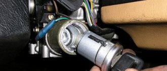
- ignition switch "6".
Functions and tasks
The module supplies high voltage to the spark plugs through the PVN. PVN are high voltage wires . Before completely changing the module, make sure that the high-voltage wires on the VAZ 2114 do not need to be replaced. Otherwise, you will waste your money.
When the module is operating, current is supplied to the spark plug. As you know, there are two of them in the car. If one is supplied with a working spark, then the second is supplied with an idle spark. The working charge is intended for cylinders 1 and 4, and the idle charge is for cylinders 2 and 3. This scheme allows the spark to be in the required cylinder during the corresponding engine stroke.
Should high-voltage wires be replaced and when?
No matter how well the armored wires are made, they also have a limited service life. According to current regulations, they must be replaced after every 30,000 km traveled. In practice, many motorists ignore this rule, continuing to travel with wires that have already outlived their useful life.
Such inattention can cause a whole host of problems, including:
- poor ignition;
- overclocking problems;
- engine tripping;
- inability to start the car.
Replacement of armored wires of VAZ 2114
All these troubles are caused by one single factor - an increase in the electrical resistance of the core of high-voltage wires, as a result of which it becomes “more difficult” for the impulse from the coil to reach its destination.
You can check whether you can still drive with the old wires or not - at home.
To do this you need:
- Turn off the ignition.
- Remove one of the armored wires.
- Measure its resistance using a megohmmeter or multimeter in the appropriate mode.
- If the resistance turns out to be equal to or close to the figure indicated on the wire insulation, then it is in good condition, but if it turns out to be greater, then the wire should be replaced.
- Repeat this operation on the remaining three wires.
Also, do not forget about the cleanliness of the contacts of high-voltage wires - they can also cause ignition problems. If oxides are noticeable on the metal tip, they should be cleaned with fine sandpaper or a cloth moistened with kerosene. By following these simple rules for caring for armored wires and replacing them, you can almost completely avoid troubles associated with the ignition system.
HOW OFTEN SHOULD I CHANGE GDP?
According to the recommendations of Avto-VAZ, replacement of high-voltage wires of the VAZ 2114 should be done every 30 thousand kilometers. In practice, motorists rarely comply with these replacement deadlines, since if the wires do not have any mechanical damage, they can travel about 100-150 thousand km.
When the service life is exceeded, the internal resistance of the GDP increases, which negatively affects the transmission of the electrical impulse. This leads to problems with ignition and acceleration dynamics, since when the supply of current to the spark plugs is delayed, the normal engine operating cycle is disrupted.
Change the wires every 25-30 thousand km and everything will be fine
How to set timing marks on a VAZ-2114 8 valves: photo and video
Marking the gas distribution mechanism on the 8-valve VAZ-2114 is an important part of repair operations. So, this process will be needed directly when adjusting the valve mechanism or replacing the timing belt
Incorrectly placed TMV tags can lead to catastrophic consequences.
What is timing belt?
Timing mechanism diagram
The gas distribution mechanism is a mechanism in which the valve timing of the power unit is controlled. For normal engine performance, there are special marks by which the timing belt must be set.
The timing marks are misaligned if the drive toothed belt is broken or if it is replaced incorrectly. So, in these cases, the engine will not work correctly and the marks will need to be re-set. Doing this is quite problematic and not everyone can do it.
Setting the tags: step-by-step instructions
Tools for working with timing marks
In order to correctly set the timing marks, you will need the necessary tools. So, what is directly required in order to perform this operation:
- Key for 10.
- Thin flathead screwdriver.
- Jack.
The process itself
Now that everything is assembled, you can proceed directly to the work process itself:
- Jack up the right side of the car.
Setting up the car on a jack - Under the hood, unscrew the timing belt protective cover.
Unscrew the mounting bolts of the timing caseRemoving the lower mounting of the timing case
Remove the unscrewed casing from the motor
- Rotate the right front wheel until the camshaft mark matches the pulley and the block.
We set marks on the camshaft and block - Remove the plug on the gearbox housing.
We look, if the marks on the flywheel and the housing coincide, then everything is fine, if not, we rotate the wheel until the mark on the camshaft and flywheel coincides with the marks on the block. Remove the crankcase plug, where the mark on the flywheel should coincide with the block - If the marks do not match even when turning the crankshaft 4-6 times, then you will have to remove the timing belt. Read more about removal and subsequent installation with the correct tension here. The camshaft mark matches, and only at this moment do we remove the strap. Next, rotate the crankshaft until the marks match on the flywheel. After performing these operations, you should put on the belt.
- Thus, the timing marks are set, and you can begin to perform other operations.
Consequences of incorrectly setting timing marks
The consequences of incorrect placement of the timing marks on the car can be both minor and very severe.
A torn timing belt on an 8-valve valve does not threaten to bend the valves, but the 16-valve version of the VAZ-2114 is already deprived of this advantage.
Let's consider the main options for the development of events:
- Misaligned timing will cause the valves to burn out.
- Bent valves (bent valves) are also an unpleasant option. The 8-valve version of the VAZ-2114 does not bend the valve.
- As a result of the above actions, the cylinder head may become deformed, guide bushings may fail, and cracks may form inside the main power elements.
- Burnout of the piston mechanism also becomes a consequence of incorrect placement of the gas distribution mechanism marks.
- Oil residue on the spark plugs, as well as poor ignition timing of the fuel mixture.
- Other consequences.
As practice shows, setting the ignition on a VAZ-2114 is quite simple, but not every motorist can do it. So, it is necessary to have knowledge of the operation of the engine and its design. Therefore, if a motorist is not able to do this type of repair on his own, he must contact a car service center.
Maintenance schedule
To avoid having to carry out expensive overhauls of the Lada Samara 2114 yourself, you should follow the manufacturer’s recommendations for servicing the internal combustion engine:
| Maintenance object | Time or mileage (whichever comes first) |
| Timing belt | replacement after 100,000 km |
| Battery | 1 year/20000 |
| Valve clearance | 2 years/20000 |
| Crankcase ventilation | 2 years/20000 |
| Belts that drive attachments | 2 years/20000 |
| Fuel line and tank cap | 2 years/40000 |
| Motor oil | 1 year/10000 |
| Oil filter | 1 year/10000 |
| Air filter | 1 – 2 years/40000 |
| Fuel filter | 4 years/40000 |
| Heating/Cooling Fittings and Hoses | 2 years/40000 |
| Coolant | 2 years/40000 |
| Oxygen sensor | 100000 |
| Spark plug | 1 – 2 years/20000 |
| Exhaust manifold | 1 year |
Features of the ignition module
Now let's talk about a more complex issue - the ignition module and its design features.
The design includes several components, each of which has its own nuances.
Component
Peculiarities
There are always two coils on a VAZ 2109. This mechanism is responsible for generating current
Switch keys also work together. Through them, the current goes to the spark plugs, plus the controller regulates the time the current is turned on, which is calculated by receiving information from the crankshaft sensor
Electronic control unit
Responsible for distributing information in the form of electronic impulses
High-strength plastic is used for its manufacture, which largely ensures the durability and reliability of the device.
Ignition coil
Location
Any work related to repair, testing, and maintenance of the ignition module will be impossible to perform if you do not know basic things - the location of the device.
You can find the ignition module (ignition module) in the engine compartment. Find the high voltage wires that go to the spark plugs. One end is connected to them, and the other goes to the module. The MZ is small in size and enclosed in a plastic housing.
Device location
Principle of operation
Initially, on carburetor cars, the system worked due to the presence of an ignition coil. With injectors everything is somewhat different.
- Initially, the ignition coil is turned on, generating a high voltage current. The coil operates on the principle of magnetic induction;
- Then the electronic control unit MZ is connected to the work, performing the functions of control, transmitting commands, and ensuring the flow of current required by the characteristics to the spark plugs;
- Next, the spark plugs activate the spark, ignition occurs, and so on.
MH malfunctions
The ignition module often shows the most basic sign of failure - lack of spark. But this is not the only indicator of a malfunction. These also include:
- Lack of dynamics when accelerating the car. Trying to quickly pick up speed, you can clearly feel failures in engine operation;
- The engine does not produce the usual power; in some cases, the engine is not able to pull the car uphill;
- The idle speed fluctuates;
- One of the pairs of engine cylinders refuses to work. Here, most likely, there is no current that should come from the ignition coil.
To eliminate problems with the MH, the first thing you need to do is check the spark plugs, and then make sure the other elements are working.
Disconnect and check
Checking the spark plugs
To check the condition of the spark plugs, which may cause the module to malfunction, you need to:
- Unscrew the spark plugs from their seats, having first removed the high-voltage wires. The elements are removed with a special key.
- Inspect the spark plugs for carbon deposits, mechanical defects, and poor clearance.
- Send defective spark plugs to a landfill and install new ones in their place.
If replacing or cleaning the spark plugs does not produce results, then the reason lies in other elements of the ignition module.
Checking the Ministry of Health
To check the node, follow these steps:
Check the condition of the high-voltage blocks going to the MH. If there are breaks or insulation failure, a spark will not form. Perform the check with a tester; The normal voltage on high-voltage wires is 12 Volts with a small permissible deviation; If the wires are OK, check the module. There are several ways to make this work; The first method is the simplest - replacing the old ignition module with a new one, the functionality of which you are sure of. But this is not an economical option, since MH is not the cheapest pleasure. Buying it for a simple test is not particularly wise; The second method involves the need to move the MH. While the engine is running, move the module and knock on it. If the motor starts to work differently, then there is simply no contact. The problem is not serious, since the module can be disassembled and all contacts secured, after which the MH will work like new; The third method is the most accurate, but also difficult. You will need a tester or ohmmeter. Measure the resistance on high-voltage wires
Pay special attention to the data on the ignition module terminals between cylinders 2 and 3 and between cylinders 1 and 2. A resistance of about 5.4 kOhm is considered normal
If there are deviations, the MH must be replaced.
Features of the system design
The heater and the entire heating system of the VAZ-2114 are in many ways similar to its predecessors. It is considered simple, which makes DIY repair possible.
Main components of the heating system:
- fan;
- stove tap (faucet or switch);
- radiator;
- air flow regulator.
The design is simple. Air is supplied inside the cabin through dampers. The resistor is responsible for the fan power and its operation. If the resistor on the VAZ-2114 stove fails, the regulator in the first and second positions stops working.
Important! If you do not change the element of the heating system and leave everything as is, then warming up the interior will take a very long time. In cold winter conditions, you will not have enough patience and health
In the VAZ-2114 heating system there are two spirals, the resistance of which is 0.23 and 0.82 Ohms. When the fan is in the first position, current is supplied through two spirals. Switching to the second position allows electricity to flow through one coil, so there is less resistance.
And when the regulator is in the 3rd position, the fan receives current from the motor, that is, bypassing the resistor. So if the stove does not work in the first two positions, then the reason is in this element of the VAZ-2114 heating system.
Nuances and location
To replace a device, you need to know where it is and why it needs to be replaced rather than repaired.
- The designers of the VAZ-2114 did not hide the resistor very far. It is located above the gas pedal. That is, you need to look for the element on the driver’s side. To access the device, you do not need to unscrew or remove anything.
- Its breakdowns are rare. Usually problems appear due to melted tip pads or burnt contacts. To fix the heating, you need to clean the contacts, buy and install a block.
- Experienced VAZ-2114 owners advise always having a new resistor in reserve. It will help you quickly, by elimination, determine the cause of the heating system problem. Not everyone can visually determine whether a resistor has burned out or not. By inserting a new one in place of the old one and checking the operation of the heater, you will see whether it is to blame or whether the problem needs to be looked for in other places.
- Principle of operation. The resistor is used to regulate the speed of the stove. It is needed to create resistance in order to reduce voltage. For the VAZ-2114 there is an element with two resistance spirals. The resistance of the first spiral is 0.23 Ohm, and the resistance of the second spiral is 0.82 Ohm. This allows you to turn on the stove in two operating modes through one resistor.
Which is better?
SOATE devices manufactured in Stary Oskol have proven themselves to be the most reliable ignition modules.
Module structure
The module consists of two ignition coils and two high-voltage switch switches.
Inside the module there is a board with radio components and ignition coils filled with compound.
The coil generates a high voltage pulse, and it is a simple transformer with two windings, primary (induction voltage about 500 V) and secondary (induction voltage at least 20 kV). All this is assembled in a single housing, on which there is a connector for signal wires (from the engine control unit) and four terminals for high-voltage wires.
Schematic diagram of the module.
The module operates on the principle of an idle spark - it distributes sparks in pairs to cylinders 1-4 and 2-3 according to impulses transmitted from the ECU.
Error codes
When diagnosing a car at a service station or if you have the appropriate equipment, you can determine some malfunctions of the ignition module.
There are several codes that will be very useful for you:
- If the coil of cylinders 1 and 4 breaks, the device will display error P0351;
- If there is a break on cylinders 2 and 3, the error code will be P0352;
- Code P3000-3004 indicates multiple misfires.
It would be a good idea to fully check the ignition module. The simplest diagnostics involves measuring the resistance between wiring of cylinders 1 and 4 and cylinders 2 and 3 with a multimeter. First switch the device to ohmmeter mode. If the indicator was 5.5 units. then everything is fine with your module.
Although there are three more ways to check:
- Check the wiring harness. Disconnect it and check with a voltmeter. The probe is directed to contact A, and the second to engine ground. Start the engine and check the indicators. A good indicator is about 12V. If there is no voltage, the coil may be faulty.
- Examine the condition of the high-voltage wires with an ohmmeter. If the high-voltage circuits are installed incorrectly, the module will simply burn out.
- Pull the block with the wires a little and tap on it. Contacts should not be lost in this case. If the opposite happens, this indicates bad contacts that can completely break off at the most inopportune moment in the very near future.
Malfunctions of high-voltage ignition wires
Main symptoms of a malfunction:
- problems starting the engine;
- unstable operation of the engine at idle speed;
- increase in CO level in the exhaust;
- increase in the level of radio interference.
Possible malfunctions come down to two groups: increased resistance and current leakage.
Increased resistance or even a complete lack of contact occurs when the interacting conductive elements oxidize and the cable is disconnected from the spark plug/coil. Both of these undesirable events potentially occur at both ends of the ignition wire, which are subject to mandatory inspection. Oxidation is often caused by excessive heat and sparking.
Video: High voltage wires
Leakage current. In practice, there is a noticeably greater variety of reasons for its occurrence. This is caused by contamination of the metal conductive components of the high-voltage part of the electrical equipment of the ignition coil and its distributor at one end. At the opposite end of the wire, contamination of the spark plug contacts, the metal tip of the high-voltage wire, and the inner surface of the protective caps is dangerous.
Another cause of leaks is insulation damage, which occurs for various reasons. They cannot cause a short circuit, but if they get dirty, a leakage current appears.
Something else useful for you:
- Engine vibration at idle speed is transmitted to the car body: reasons and what to do?
- When can a car “jerking” appear and what are the reasons for this phenomenon?
- The starter turns, but the internal combustion engine does not start: reasons and what to do?
Finding the ignition moment in the ignition
On engine 402, ignition adjustment occurs according to the following algorithm and order:
- The crankshaft occupies a spatial position corresponding to 5 degrees of advance in ignition of the fuel mixture;
- This position can be easily achieved by aligning the mark on the pulley with the recess on the motor block;
- The coincidence means that the power plant has marked the end of a full piston stroke.
With the distribution sensor removed, adjustments are made as follows:
- I remove the spark plug from the head of the combustion chamber of the cylinder, which is listed as No. 1 in the order of fuel ignition;
- I cover it with a sheet of paper and turn the engine crankshaft;
- The air pushed out by the piston blows off the sheet, which indicates that it has reached the vertical maximum, from which the stroke begins;
- Then, using the keys, I set the octane corrector scale to 0.
What does a car owner need to know about spark plugs?
All modern cars have an internal combustion engine. The energy required to operate a car is obtained through the combustion of the fuel mixture inside the engine cylinders. Automotive SZ are designed to ignite a combustible mixture. Engine starting, power and fuel consumption depend on their serviceability. Therefore, you need to know when to change spark plugs and perform this procedure on time.
Gasoline engines use spark SZ, they consist of the following elements:
- metal case;
- central electrode;
- one or two side electrodes;
- metal tip for connecting a high-voltage wire;
- ceramic insulator.
SZ are under heavy load, and the uninterrupted operation of a gasoline engine depends on their serviceability (video author - ZapPrivozTV).
What are the requirements for spark plug wires?
Any conductor has a certain service life. If the cables are laid in a bundle, have an outer braid and are fixed permanently (protected from vibration loads), the service life is equal to the life expectancy of the car. Another thing is the high-voltage ignition coil wire. It is located in the epicenter of unfavorable conditions: vibration, high temperature (as well as changes in winter), gasoline vapors, therefore high demands are placed on the quality of insulation of high-voltage wires and the core:
- The conductors are exclusively copper (as is known, this material has the lowest resistance), but the protective layer can be silicone or rubber. Other insulation materials, although they have good protection, are not soft enough. Another requirement for high-voltage wires is elasticity. Otherwise, the surface will simply crack due to constant vibration;
- Shell thickness is a compromise. If a breakdown of high-voltage wires occurs, a spark will form between the central core and the motor housing. The voltage will not reach the spark plug, but the presence of a sparking conductor in the engine compartment, to put it mildly, is not useful for the car. The other side of the coin is that a wire that is too thick is inconvenient to install, it is inelastic, which makes installation and maintenance difficult;
- The length of high-voltage wires is another headache for the manufacturer. From Ohm's law it is known: the shorter the conductor, the less losses for electric current. In a car, it is not so easy to place all the interacting components next to each other. Mounting the ignition coil above the spark plug wells is good for electricians, but bad for builders. In addition, it is desirable that the cables be of similar length, so the connection diagram for high-voltage wires is carefully calculated, and replacing the cables with universal ones means disrupting the operation of the entire ignition system on the car.