The principle of operation of the starter is as follows: in order to start the car engine into operating mode, it is necessary to forcibly rotate the crankshaft until the fuel mixture in the cylinders begins to burn. This is where the idea arose that it was time to change the car to a foreign car. To be honest, I didn’t manage to start making money right away, until I understood all the mechanics of options, I lost about rubles, but as it turned out, it was a precious experience.
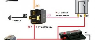
If the repair does not give the desired results, check the electrical circuit. To solve the problem of a weak starter, vehicle designers and developers adopted the VAZ auxiliary starter relay. Wiring for installing an additional starter relay. VAZ injector starter connection diagram.
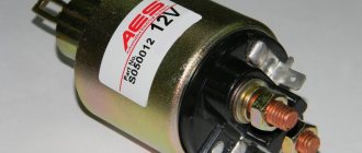
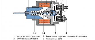
As you can see, the changes are minimal: 1. After completing the installation, check the functionality of the additional relay by purging the cylinders. Unlike a conventional relay, the solenoid relay performs two functions at once - it closes and opens the contacts of the electrical circuit, and, with the help of the core, moves the bendix gear to engage with the flywheel of the internal combustion engine. A suitable place for this is the stud of the washer reservoir.
Most often, electromagnetic circuits burn out.
When it is pressed, voltage is supplied to one of the control contacts of the relay, and it closes the power circuit - the lamps in the headlights light up. The principle of operation of the starter is as follows: in order to start the car engine into operating mode, it is necessary to forcibly rotate the crankshaft until the fuel mixture in the cylinders begins to burn.
VAZ 2110 starter circuit; eleven; 12. In detail and in detail.
Main starter relay
The car's electric starting system includes, in addition to the starter and relay, also starter on/off elements, various connecting wires, the main power source (battery), etc.
The starter relay or VR is activated after turning the key in the ignition switch. The BP armature and the freewheel lever move, and the bendix engages with the flywheel crown. This ensures normal engine starting.
To be able to adjust the system, you need to disconnect the current wiring from the VR. The control terminal is marked on the terminal with the letter M.
Then the battery is removed from its original place and connected to the M and S terminals marked on the terminals. Thus, the purpose of the operation performed is to shift the bendix. And in order to connect the BP to the starter, you must first adjust the gap between the bendix and the stop. It is also recommended to adjust the gasket located between the drive and the BP.
VAZ-2101 diagram
The “penny” circuit diagram guide is intended for self-repair of a car in case of minor electrical equipment problems. Start the repair by checking the fuses and relays (description and designation will follow). The electrical circuits are divided into several blocks (for ease of viewing via a computer or phone), there are files in the form of a single picture with a description of each element - for printing on a printer. This is a small car, an analogue of the Fiat 124. Years of production of the VAZ-2101: from 1984 to 2014.
As in all other Zhiguli models, the electrical wiring of the penny is made according to a single-wire circuit. Power is supplied to all electrical devices through one wire, and the negative wire is the car body.
Additional VR starter
On modern cars, an additional VR starter is a priori provided. On older cars, the relay is installed and connected independently.
The advantages of installing an additional VR are obvious:
- Protects the starter device from burnout of contacts in the lock, which occurs for various reasons (long start-up, banal wear, etc.);
- It has a positive effect on the loading of contacts of the same ignition switch, as a result of which the contacts remain operational longer;
- Protection of the starter from a situation where, due to a “glitch” of the key in the ignition switch (the engine has started, but the starter continues to spin).
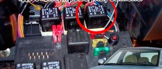
You can check whether the additional VR is installed on the car like this:
- Look in the “black box” (fuse box);
- Turn on the starter device in the engine purging mode - if the additional relay is on, then the starter must turn off on its own after a few seconds.
Connection of additional VR
Here's how to connect:
- Fix the relay in any convenient place (you can on the stud of the glass cleaning fluid reservoir);
- Connect the cable to the starter;
- Remove the red wire from the flat terminal of the main relay, and in its place insert the wire from the additional VR;
- Connect the other wire of the new BP with an 8 mm tip to the positive of the starter;
- Place contact 30 of the additional VR onto the released contact of the main VR;
- Screw the short wire numbered 85 to the body (ground).
Additional relays can be purchased in stores. They are sold as a kit, where everything is provided for proper self-installation.
Forget about fines from cameras! An absolutely legal new product - NANOFILM, which hides your license plates from IR cameras (which are installed in all cities). More details at the link.
- Absolutely legal (Article 12.2.4).
- Hides from photo and video recording.
- Installs independently in 2 minutes.
- Invisible to the human eye, does not deteriorate due to weather.
- 2 year warranty
Historical reference
Traditionally, the UAZ 469 was produced in two versions:
- Cargo-passenger version - 7 seats and 100 kg of luggage;
- Commander version - 2 seats for passengers and 600 kg of luggage.
For reference: regardless of the version, the UAZ 469 can tow a trailer with a total weight of 850 kg.
Industry standard 1945
According to the old vehicle classification system, in force since 1945, the UAZ 469 was produced under this name, using an alphanumeric name:
- The letter abbreviation UAZ stood for Ulyanovsk Automobile Plant;
- 469 is a serial factory index assigned by the enterprise itself to its models and developments.
For reference: according to the industry standard of 1945, each automobile plant was assigned a specific numbering. For MZMA, which produced Moskvich 408 and 412, these are numbers from 400 to 449, for the Ulyanovsk Automobile Plant these are numbers from 450 to 484, etc.
1966 Industry Standard
Although at the time of the release of the UAZ 469 (1972) a new industry classification system was adopted (industry standard OH 025270-66), the car plant continued to use the name according to the old standard.
Starter relay description purpose device repair photo video
Share “Starter relay description purpose device repair photo video”
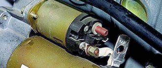
The movement of any car begins with starting the engine . If you want to understand the principles of operation of the main components of a car, we recommend starting your study with the starting system. One of the most vulnerable points of this system is the starter relay. Almost everyone has heard about this detail, but not many understand the principle of its operation. Before we start talking about the starter relay, it is worth noting that the design of the car simultaneously has two parts with the same name, only the first is responsible for turning on the starter, it is usually located in the engine compartment, and the second is the starter solenoid relay.
WHAT IS A STARTER RELAY
So, let's start with the basics. Two relays are responsible for the starter. The first is installed in the engine compartment. The design can have its own housing or be installed in a common unit.
In this article, we will be much more interested in the second relay, which is responsible for the operation of the starter, namely the retractor. It performs the following functions:
- redistributes energy between the starter and the electromagnetic relay;
- feeds Bendix gears;
- synchronizes the starter components,
- returns the gears to their original position after you turn off the engine.
In the automotive world, this unit has two names: traction and retraction. The first is most often used in specialized literature, the second is popular.
To understand why a starter solenoid relay is needed, let’s look at the engine’s operation schematically. To start the engine, the crankshaft must begin to rotate. Only after this does the fuel-air mixture ignite in the combustion chamber.
Usually the engine starting process takes place within a second. The role of the relay in it is quite simple. Thanks to it, the gear elements engage with each other. It synchronizes the operation of the starter. This unit also removes the bendix from the flywheel.
Main components and operating principle of the engine starting system
To understand the operation of the starting system, it is worth first considering the design of the car starter. The purpose of the starter is to start the engine. The starter device for all cars is identical, they differ only in size or parameters. So, the design consists of the following required elements:
- Electric DC motor;
- Bendix;
- Starter solenoid relay.
The main role here is played by the electric motor, and the bendix and starter relay are auxiliary elements. The electric motor includes standard elements such as a stator, a rotor, and a starter brush assembly. Bendix, even the smallest detail, plays a very important role. It is necessary to transmit rotation from the electric motor to the gear ring of the engine flywheel, thereby ensuring starting.
Until 2000, the bendix was located on the same shaft as the rotor, and then a new arrangement appeared, where the bendix began to have its own separate shaft and rotate through a gearbox.
That’s why we sometimes hear the name “gear starter”. The starter retractor relay is a more complex element and performs several functions at once:
- Redistribution of electricity supplied from the battery between the electric magnet of the starter relay and the electric motor;
- Synchronization of the operation of all components when starting the engine;
- Feeding the Bendix gear until it engages with the flywheel ring gear;
- Returning the working gear to its original position after starting the engine.
The principle of operation of the starter is as follows: in order to start the car engine into operating mode, it is necessary to forcibly rotate the crankshaft until the fuel mixture in the cylinders begins to burn.
Typically, it takes quite a bit of time to start a working engine. The task of the starter retractor relay is to maintain the engagement of the Bendix gear with the flywheel and rotate the crankshaft equally until the start occurs. No more and no less. If you hold it longer, you can break parts, and if you hold it longer, the engine won’t start.
Stories from our readers
“Fucking basin. "
Hi all! My name is Mikhail, now I’ll tell you a story about how I managed to exchange my two-wheeler for a 2010 Camry. It all started with the fact that I began to be wildly irritated by the breakdowns of the two-wheeler, it seemed like nothing serious was broken, but damn it, there were so many little things that really started to irritate me. This is where the idea arose that it was time to change the car to a foreign car. The choice fell on the melting Camry of the tenth years.
Yes, I had matured morally, but financially I just couldn’t handle it. I’ll say right away that I am against loans and taking a car, especially not a new one, on credit is unreasonable. My salary is 24k a month, so collecting 600-700 thousand is almost impossible for me. I started looking for different ways to make money on the Internet. You can’t imagine how many scams there are, what I haven’t tried: sports betting, network marketing, and even the volcano casino, where I successfully lost about 10 thousand ((The only direction in which it seemed to me that I could make money was currency trading on the stock exchange, they call it Forex. But when I started delving into it, I realized that it was very difficult for me. I continued to dig further and came across binary options. The essence is the same as in Forex, but it’s much easier to understand. I started reading forums, studying trading strategies. I tried it on a demo account, then opened a real account. To be honest, I didn’t manage to start earning money right away, until I understood all the mechanics of options, I lost about 3,000 rubles, but as it turned out, it was a precious experience. Now I earn 5-7 thousand rubles a day. I managed to get the car buy after half a year, but in my opinion this is a good result, and it’s not about the car, my life has changed, I naturally quit my job, I have more free time for myself and my family. You’ll laugh, but I work directly on the phone)) If If you want to change your life like me, then here’s what I advise you to do right now: 1. Register on the site 2. Practice on a Demo account (it’s free). 3. As soon as you get something on the Demo account, top up your REAL ACCOUNT and go to REAL MONEY! I also advise you to download the application to your phone, it’s much more convenient to work from your phone. Download here.
- The controller controls the on/off of the additional starter relay depending on the crankshaft speed and the time the starter cranks the engine.
- After setting the ignition key to the “Starter” position and the crankshaft rotation speed not exceeding 500 min1, the controller sends a signal to an additional relay and thus turns on the starter.
- After being turned on, the starter will work until the ignition key is in the “Starter” position for no more than 20 seconds, provided that the “correct” password has been received from the immobilizer and the crankshaft speed has not increased to 500 min1. This prevents the starter from turning on when the engine is running and its overheating during prolonged cranking.
DIAGNOSTICS AND REPAIR
CHECKING THE SYSTEM
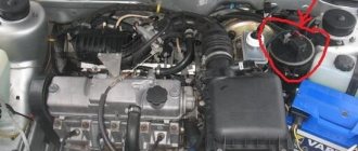
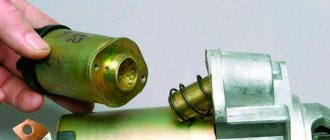
Before checking the solenoid relay, you need to test the starter itself. This check will allow you to understand what exactly is not working in the system. Insert the key into the ignition and turn it.
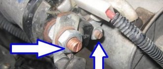
Next you will need to open the hood and get to the starter. You must make sure that this is the case. To do this, bridge the two contacts. They are made in the form of two copper bolts. These structural elements are attached to the rear of the solenoid relay (on the body). If, after the manipulations you have performed, the mechanism rotates, then the problem is in the solenoid relay.
In some cars, reaching the starter is very difficult, and sometimes even impossible. In this case, you will have to partially disassemble the system and dismantle the device itself.
After removing the starter, place it on the ground. Place the battery nearby. Connect the leads of the two devices. In this case, the battery ground is connected to the starter ground.
When the wires are connected, the starter solenoid relay will operate. At first there will be a rather loud click. If the mechanism operates too slowly, be sure to check the contacts. This situation may be caused by the fact that they are burnt.
Checking the retractor relay with the starter removed
It is more convenient to check the functionality of the relay with the starter removed. But before dismantling, several operations are performed to identify the problem:
- Check the reliability of the terminals, the condition of the battery, remove oxides from the contacts and terminals of the battery.
- Make sure that the wiring is securely fastened to the starter with nuts. If corrosion is noticeable, clean the contacts with fine sandpaper.
- Check the condition of the starter enable relay.
The starter is removed after disconnecting the wires that go to it and unscrewing the mounting bolts. In some cars, this operation will take a lot of effort, since the unit may be located in a poorly accessible engine compartment.
After removing the starter, it is cleaned of dirt, the oxidized contacts are treated with sandpaper, and the test begins in the following order:
- The unit is placed next to the battery, from the terminals of which there are wires with “crocodiles”.
- The positive and negative terminals are connected to the corresponding contacts on the retractor.
- The free end of the negative wire is touched to the starter housing and the result is observed:
- If there is a distinct click in the relay, then it is working;
- If the retractor does not show “signs of life,” it needs to be replaced or repaired.
WHAT DAMAGES CAN BE IN THE EXTRACTOR RELAY
Usually the whole problem lies in burnt contacts or their sticking; other faults include:
- coil burnout,
- mechanical damage,
- natural wear and tear of parts.
In the latter case, the starter solenoid relay will need to be replaced. There are a number of signs that most likely indicate that the problem is in this particular node, these include:
- After the engine starts, the starter continues to operate. This is indicated by a clearly audible buzzing sound.
- When you turn the key in the lock, you can hear a distinct clicking sound. This means that the main system starts, but the starter does not work.
- When you turn the key, the starter idles. The engine remains inactive.
These signs most likely indicate that the malfunction is related to the starter solenoid relay.
HOW TO CONNECT
Many motorists are afraid that after they repair the solenoid relay, they will not be able to connect it. In reality, the connection diagram is quite simple. Moreover, you compose it yourself.
To carry out reverse dismantling, you must first mark the disconnected terminals. This will allow you to connect everything correctly after the repair is completed. Also, before installing the relay, you need to clean the contacts. For degreasing, use a modern liquid sold in automotive stores.
REPAIR
It is worth recognizing that on machines of the same series, the starter solenoid relays are very similar. The most striking in this context is the following automobile line:
In principle, all starter solenoid relays have the same design. Accordingly, their repair process is similar. The main differences lie in the fastening systems. Also, cores can have different designs. But the general scheme is very similar.
So, in order to repair the starter solenoid relay, you first need to dismantle and disassemble it. Here, in fact, lies the main problem. In most cars, these units are non-separable. All that remains for the driver in this case is to make a replacement.
This is interesting: Installation diagram of window lifter cables for UAZ loaf
It is very important to maintain a clear sequence during repairs. Otherwise, you risk not only damaging the part or other systems, but also getting injured. The process itself consists of the following stages:
- Disconnect power from the battery.
- Clean the part from dust and dirt. Otherwise, foreign particles may get inside the unit, causing damage to it.
- Unscrew the brush assembly nut.
- Remove the contact from the bolt.
- Unscrew the clamping screws. They are the ones that connect the relay to the ground of the car.
- Unscrew the ends of the nuts.
- Divide the device in half.
- Replace the core.
- Reassemble.
Before putting the device back into the car, start it. Reinstallation should only be carried out after preliminary testing. Once everything is assembled, do a few test runs. Only after this go on the road.
WHAT ELSE CAN BROKE?
Most damage to the solenoid relay is associated with the burnout of certain of its elements. Most often, electromagnetic circuits burn out. Windings and contacts are also subject to similar destruction. In some cases, the cause of failure is metal fatigue.
However, ignition problems are not always associated with the starter or solenoid relay. If the repair does not give the desired results, check the electrical circuit. Also look at how much charge the battery has.
Every car owner can check and repair the solenoid relay. The process itself does not take much time, and its complexity in most cases depends on how conveniently the starter is located.
Share “Starter relay description purpose device repair photo video”
What kind of problems are there?
Now it’s worth talking about the malfunctions that occur when using car starters. Although we are talking about car starters, you should understand that even chainsaws have them. Not long ago I found out about this myself when I was watching a video about repairing this instrument.
Malfunctions are really different. But, depending on the reasons, they can be divided into electrical and mechanical.
If there is an electrical problem, you should check:
- Traction relay. It sometimes fails. Repair is unlikely to help. It is possible that there was a gradual break in the existing winding, or a short circuit between different turns. The element or the entire starter needs to be replaced. Decide for yourself here;
- Brushes. We are interested in the entire brush assembly. Quite often it happens that the brushes simply no longer adhere properly to the commutator. Hence the starter failure;
- Anchor collector. Usually it wears out, which creates the need for repairs or a complete replacement.
The starter can turn the engine, but it does so slowly or does not function at all. Try checking the electrical circuit. It's not that difficult to do if you work carefully.
To check the electrical circuit you need:
- make sure the car battery is well charged;
- check the fastening of the ground contacts;
- look at the integrity and quality of contact of the wiring from our retractor;
- make sure there is no damage or poor contact on the wire running from the battery to the starter;
- make sure that the contact group of the lock itself works well.
There is nothing particularly complicated here. Therefore, you should easily be able to do it yourself. But if you are not sure, it is better to contact a car service.
As for mechanical problems, they are indicated by a working starter, in which the engine does not start or the crankshaft does not rotate.
Here's what you should check:
- Coupling. It slips and therefore cannot fulfill its function;
- Buffer spring;
- Starter flywheel crown. More precisely, its teeth. This problem is indicated by a grinding noise that occurs during startup;
- Clutch rings. These elements sometimes wear out ahead of time, and therefore the operation of the entire system is disrupted;
- overrunning clutch lever.
The presence of uncharacteristic noise should be a reason to look into the starter through the engine compartment or using a hole.
Noise usually occurs due to:
- wear of starter bearings;
- wear of the journals on the armature shaft;
- damage to teeth;
- your starter's mounting bolts are loose;
- loose pole attachment.
There is another situation when the starter has done its job, but does not stop, but continues to turn even after the car engine has started. Here the levers are probably stuck, the soured contacts on the starter relay are stuck together, the traction is stuck, or the spring of the switch is seriously worn out.
The starter is a rather serious thing, the problems of which should be approached very carefully. Any symptoms of malfunctions tell you that you need to promptly check the device and take appropriate measures.
Thanks to all! Subscribe, leave comments and tell your friends about us!
Car starter connection diagram
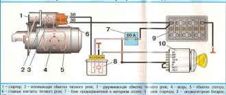
A lot of time has passed from the time the car was created, or rather the introduction of a starter into it, to the present day, but the scheme has remained virtually unchanged. The first connection diagram for the starter looked approximately as shown in the figure below, now it has changed a little, which I will explain below.
The battery positive (1) is connected by a thick wire to the starter terminal (3). The starter current at start-up can reach hundreds of amperes. Next, the plus, through the generator (2), is supplied to the ignition switch (5). After closing the ignition switch contacts, the intermediate relay coil (4) is energized, which closes its contacts. One of the relay contacts is connected to the positive wire, therefore, after their closure, the windings of the solenoid relay are energized. We will look at how the starter and solenoid relay work in another article.
Such schemes were used in Soviet-made cars; foreign cars, if they used them, moved away from such schemes very quickly. The first starters were massive and had low efficiency. Consequently, the control circuits required the same not small currents. An intermediate relay is used to pass these currents. Modern starters have less power. This was achieved by using permanent magnets on the stator poles and installing a step-down gearbox on some models. This made it possible to get rid of the intermediate relay and supply voltage from the ignition switch directly to the coils of the solenoid relay.
Computer keyboard circuit Starter blocking device Simple starter blocking Power supply for 9-volt radio equipment from the car's on-board network Circuit of a desulfating charger Simple stabilized power supply with super-available parts Laboratory power supply controlled by a microcontroller Laboratory power supply from an AT power supply Power supply from an uninterruptible power supply
Scheme of the “penny” brake system
1 – front brake protective housing; 2, 18 – pipelines connecting two cylinders of the front brake caliper; 3 – caliper; 4 – hydraulic drive reservoir; 5 – brake light switch; 6 – parking brake lever; 7 – adjusting eccentrics of the right rear brake; 8 – fitting for bleeding the hydraulic drive of the rear brakes; 9 – pressure regulator; 10 – stop signal; 11 – rear brake wheel cylinder; 12 – lever for manual drive of the pads and expansion bar; 13 – adjusting eccentric of the left rear brake; 14 – brake pad; 15 – rear cable guide; 16 – guide roller; 17 – brake pedal; 19 – fitting for bleeding the hydraulic drive of the front brakes; 20 – brake disc; 21 – main cylinder
The 2101 brake system has two circuits that provide independent drive of the front and rear wheel brakes. Both circuits are driven by a single pedal, which is attached to the front panel of the body using a bracket along with the clutch pedal.
How to make a start button instead of an ignition key in a car with your own hands
Oddly enough, this issue very often worries motorists and not only for aesthetic reasons - in the spirit of the times. The contact group located behind the ignition key very often fails, and changing it is far from an easy task.
In older cars, often the wires from the starter itself are connected directly to contacts inside the contact group, which close when the ignition key is turned. When the starter is activated, a very large amount of energy is consumed, which means a large current flows (the contacts strike a spark). Over time, a burnt deposit forms on the contacts or they completely burn out, no longer providing reliable contact. Newer vehicles have a separate relay that closes the starter contacts when the ignition key is turned.
Another version of the VAZ-2101 scheme
Outdoor Lighting
1 – Headlights 2101 2 – engine compartment lamp; 3 – battery; 4 – generator; 5 – reverse light switch; 6 – fuse block; 7 – indicator lamp for external lighting in the instrument cluster; 8 – glove box lighting lamp; 9 – instrument cluster lighting lamp; 10 – plug socket for a portable lamp; 11 – instrument lighting switch; 12 – external lighting switch; 13 – brake light switch; 14 – ignition switch; 15 – lamp switches located in the front door pillars; 16 – lamp switches located in the rear door pillars; 17 – lampshades; 18 – trunk lighting lamp; 19 – rear lights; 20 – license plate light; 21 – reversing lamp
Turning on the headlights 2101
1 – headlights VAZ 2101; 2 – battery; 3 – generator; 4 – fuse block; 5 – headlight switch; 6 – external lighting switch; 7 – ignition switch; 8 – indicator lamp for high beam headlights in the instrument cluster
Direction indicators
1 – sidelights VAZ 2101; 2 – side direction indicators; 3 – battery; 4 – generator; 5 – ignition switch; 6 – fuse block; 7 – relay-interrupter of direction indicators; 8 – indicator lamp for direction indicators; 9 – direction indicator switch; 10 – rear lights
Sound signals 2101
1 – sound signals; 2 – battery; 3 – fuse block; 4 – sound signal switch; 5 – generator VAZ 2101.
Wiper circuit
1 – generator VAZ 2101; 2 – battery; 3 – ignition switch; 4 – windshield wiper switch; 5 – windshield wiper relay; 6 – windshield wiper gearmotor; 7 – thermobimetallic fuse; 8 – windshield wiper switch located in the glass washer pump; 9 – fuse block.
Heater fan Zhiguli
1 – generator VAZ 2101; 2 – battery; 3 – ignition switch; 4 – fuse block; 5 – heater switch; 6 – additional resistor; 7 – heater fan electric motor.
Ignition block diagram
The lock is attached to the steering shaft. Some of the power circuits, which are protected by fuses, are connected directly to the battery, regardless of the position of the key:
- interior lamp;
- sound signal;
- cigarette lighter;
- stop signal.
The main advantages of using a relay in the starter power circuit:
— Such a system is more reliable, since the relay is designed for high currents and lives much longer. — The relay can always be replaced — The contact group behind the ignition key works for a very long time, since it only turns on the relay that takes the main load.
Regardless of whether your starter is turned on by a relay or directly by a contact group, all operations to connect the starter are still performed by turning the key.
First you need to determine which contacts are responsible for the start and connect them to the start button.
To do this, you need to disassemble the plastic protection under the steering wheel of your car. Very often, a connector with all the necessary wires is connected to the contact group of the key well at the back. There should be locking tabs on both sides of this connector. You need to press on them and pull out the connector.
If you have an old car, inspecting the contact group connector you will most likely find the two thickest wires. Very often one of them is red - these wires are directly connected to the starter. If you connect them with the ignition key turned, your starter will most likely start spinning.
Then you can go the simple way. You can simply install the button and connect these two wires to it, placing the button in a place convenient for you. The button should be non-latching, that is, when pressed, it should close the contacts, and immediately after you release it, open it.
Do not forget that you will operate the button in the same way as a key. We press the button, wait until the starter spins, and as soon as the engine starts, release the button.
But do not forget that very large currents will pass through the button and most likely such a button will burn out.
We used a vandal-proof chrome button - it failed after about half a year.
If you have a newer car and the starter in it is connected using a relay, you will need to find among the many wires exactly those that are responsible for controlling the relay.
To do this, you can ring the tester in resistance measurement mode on all the wires on the car body. All wires that ring are marked as ground (or minus), since they are all shorted to the body.
Next, touch each of the remaining wires with one tester probe and the other probe to the body in voltage measurement mode.
We need to find the wire on which 12 Volts appears exactly at the moment you turn the key, that is, when your starter starts spinning.
If you find this contact, you need to check how the system works.
— Find some kind of contact on which, relative to ground, there is always 12 Volts.
— Turn the ignition key to ignition mode (the starter must be turned off)
— Check again the wire you found:
* check that it is not connected to ground and is not short-circuited to the body,
* check that voltage appears on it when you turn the key to the starter mode
- Now try using a separate wire to connect the wire that you found in the paragraph above to the wire that always has 12 Volts.
If after connecting your starter turns over, then you have found the wires that connect when you turn the key so that the starter turns over.
Your work is finished here. You just need to bring these wires to a convenient location on the dashboard and connect the button to them.
If your car is an old model, it is best for you to install a separate relay to turn on the starter and close only the relay contacts, which in turn will connect the starter contacts.
You can see which contacts are responsible for what on the relay body, or you can open it and see how it works.
Oddly enough, it makes absolutely no difference where to connect + (plus) and where - (minus) on the contacts of the relay coil - in any case, it attracts the desired contact and connects the line.
That is why you can use the positive contact with 12 Volts already connected to the relay. It can be connected to the coil contact. Accordingly, the second contact is connected to ground through the button.
It is these two wires - minus (ground) - the second contact of the coil that must be brought out in a place convenient for you and the button connected to them.
The remaining relay contacts for the main line must be connected to the wires on the contact group that connect the starter.
Don't forget about high power when connecting these wires. The wires must be very thick and the connections very secure.
The wires can be directly soldered to the relay contacts, but most likely this will be a mistake, since it will be quite difficult to replace it later. In our case, when heating the contacts with a soldering iron, they melted the plastic body of the relay and moved, closing the contacts inside the relay.
It is best to find a remote connector for such relays, which is sold separately. Unfortunately, it does not please with its reliability or quality of workmanship.
The wires on the connector pins are very thin and very difficult to hold on to. We recommend that you remove each pin and solder secure thick wires to them.
For convenient connection, you can attach screw terminals to the wires.
It is best to place the relay in a place where it will be convenient for you to reach it later to replace or check the operation of the system.
Remember that you do all the above actions at your own peril and risk; we do not recommend that you undertake such complex electrical work if you do not have skills in electrical engineering. We wish you good luck in all your endeavors.
Fuse and relay block VAZ 2101
If short circuits occur in the circuit during vehicle operation, the current strength in the damaged area increases. If the damaged circuit is not disconnected from the network, it can very quickly drain the battery, the wires can overheat, which will cause a greater likelihood of a fire, melting the wires and the upholstery of the car. In order to avoid this, the entire electrical wiring diagram is divided into ten zones, the state of which is controlled by a specific fuse.
Only electromagnetic relays were installed on the penny, and most of them were located under the hood of the car. Only the turn signal relay was installed under the instrument panel.
- Fuse No. 1 (16A) protected the horn, emergency carry socket, interior lamps, cigarette lighter and brake lights;
- Fuse No. 2 (8A) served the electrical circuit of the relay and windshield wiper motor, and the electric motor of the interior heater;
- Fuse No. 3 (8A) – high beam indicator lamp and left headlight (high beam);
- Fuse No. 4 (8A) – right headlight (high beam);
- Fuse No. 5 (8A) – low beam left headlight 2101;
- Fuse No. 6 (8A) – low beam of the right headlight 2101;
- Fuse No. 7 (8A) – side light indicator lamp, left sidelight lamp, right rear side lamp side light, trunk light, rear license plate light, instrument cluster illumination lamp;
- Fuse No. 8 (8A) – side light of the right side headlight, cigarette lighter light, side light of the left rear light, engine compartment lighting lamp;
- Fuse No. 9 (8A) protected the warning lamps on the dashboard: oil pressure lamp, coolant temperature lamp, fuel level and brake fluid level warning lamp, turn indicators and low battery charge lamp;
- Fuse No. 10 (8A) protected the generator excitation winding circuit and the voltage regulator.
How to connect a starter relay: rules for connecting a relay
As you know, normal functioning of a car is impossible without a good and clear start. When setting up the electric starting system of a car, great importance should be paid to the “starter-relay” circuit. It is important to know how to connect the starter relay so that no difficulties arise in the entire starting system.
Main starter relay
The car's electric starting system includes, in addition to the starter and relay, also starter on/off elements, various connecting wires, the main power source (battery), etc.
The starter relay or VR is activated after turning the key in the ignition switch. The BP armature and the freewheel lever move, and the bendix engages with the flywheel crown. This ensures normal engine starting.
How to properly connect the starter relay
To be able to adjust the system, you need to disconnect the current wiring from the VR. The control terminal is marked on the terminal with the letter M.
Then the battery is removed from its original place and connected to the M and S terminals marked on the terminals. Thus, the purpose of the operation performed is to shift the bendix. And in order to connect the BP to the starter, you must first adjust the gap between the bendix and the stop. It is also recommended to adjust the gasket located between the drive and the BP.
Additional VR starter
On modern cars, an additional VR starter is a priori provided. On older cars, the relay is installed and connected independently.
The advantages of installing an additional VR are obvious:
- Protects the starter device from burnout of contacts in the lock, which occurs for various reasons (long start-up, banal wear, etc.);
- It has a positive effect on the loading of contacts of the same ignition switch, as a result of which the contacts remain operational longer;
- Protection of the starter from a situation where, due to a “glitch” of the key in the ignition switch (the engine has started, but the starter continues to spin).
This is interesting: Wiring diagram for VAZ 2114 power windows
How to connect the additional starter relay
You can check whether the additional VR is installed on the car like this:
- Look in the “black box” (fuse box);
- Turn on the starter device in the engine purging mode - if the additional relay is on, then the starter must turn off on its own after a few seconds.
Connection of additional VR
Here's how to connect:
- Fix the relay in any convenient place (you can on the stud of the glass cleaning fluid reservoir);
- Connect the cable to the starter;
- Remove the red wire from the flat terminal of the main relay, and in its place insert the wire from the additional VR;
- Connect the other wire of the new BP with an 8 mm tip to the positive of the starter;
- Place contact 30 of the additional VR onto the released contact of the main VR;
- Screw the short wire numbered 85 to the body (ground).
Additional relays can be purchased in stores. They are sold as a kit, where everything is provided for proper self-installation.
How to pay TWICE LESS for GASOLINE
- Gasoline prices are rising every day, and the car's appetite is only increasing.
- You would be happy to cut costs, but is it possible to live without a car these days!?
But there is a completely simple way to reduce fuel consumption! Don't believe me? An auto mechanic with 15 years of experience also didn’t believe it until he tried it. And now he saves 35,000 rubles a year on gasoline! Read more about this at the link.
Electrical equipment VAZ 2101
Scheme of a penny in parts:
1 – headlights 2101; 2 – front direction indicators; 3 – side direction indicators; 4 – battery; 5 – battery charge warning lamp relay; 6 – relay for turning on low beam headlights; 7 – relay for turning on the high beam headlights; 8 – generator; 9 – starter; 10 – engine compartment lamp; 11 – spark plugs; 12 – oil pressure warning lamp sensor; 13 – coolant temperature indicator sensor; 14 – sound signals; 15 – ignition distributor; 16 – windshield wiper gear motor; 17 – brake fluid level warning lamp sensor; 18 – ignition coil; 19 – electric motor for windshield washer; 20 – voltage regulator; 21 – heater electric motor; 22 – glove box lighting lamp; 23 – additional resistor of the heater electric motor; 24 – plug socket for a portable lamp; 25 – parking brake warning lamp switch; 26 – brake signal switch; 27 – relay-interrupter of direction indicators; 28 – reverse light switch; 29 – fuse block; 30 – relay-interrupter for the parking brake warning lamp; 31 – windshield wiper relay; 32 — heater motor switch; 33 – cigarette lighter; 34 – lamp switches located in the rear door pillars; 35 – lamp switches located in the front door pillars; 36 – lampshades of VAZ-2101; 37 – ignition switch; 38 – instrument cluster; 39 – coolant temperature indicator; 40 – control lamp for high beam headlights; 41 – indicator lamp for external lighting; 42 – turn signal indicator lamp; 43 – battery charge indicator lamp; 44 – oil pressure warning lamp; 45 – control lamp for parking brake and brake fluid level; 46 – fuel level indicator; 47 – fuel reserve warning lamp; 48 – instrument cluster lighting lamp; 49 – headlight switch; 50 – direction indicator switch; 51 – sound signal switch; 52 – windshield washer switch; 53 – wiper switch; 54 – external lighting switch; 55 – instrument lighting switch; 56 – sensor for level indicator and fuel reserve; 57 – trunk lighting lamp; 58 – rear lights; 59 – license plate light; 60 – reversing lamp
Full size wiring diagram (for printing):
What does it mean “the starter takes over the current”?
The main reasons why the starter can take on current are:
- Lack of good contact on electrical wiring and elements of the ignition system;
- Sufficiently low electrical or high mechanical resistance;
- Failure of the constituent elements (due to the deterioration of the bushings, the armature begins to touch the starter when rotating). This leads to strong heating and destruction of parts. The gearbox also needs to be checked, because it may also need additional lubrication.
Your actions
To understand the true reason, it is necessary to carefully study the mechanism and check all its elements. The first step is to determine the location of this mechanism. Access to it is usually very limited, but you can get it by hand. It is also important to make sure that the battery is charged, since drivers often leave the car with the headlights on, and their work greatly drains the battery.
If the battery is in perfect order, then you should check the starter, for this you will need a power class=”aligncenter” width=”600″ height=”402″[/img] So, a thick wire is supplied from the battery to the starter, which is connected to a large bolt on relay (this is the positive terminal). You need to connect the positive contact of the multimeter to it, as a rule, this is the red wire. And the black wire with a negative contact must be connected to the ground of the car. And when you turn the key in the ignition, check what the instrument display shows. If the battery is working well, the voltmeter will show twelve volts, and the starter will make characteristic clicks. If clicks occur and the display shows less than twelve, then perhaps the reason is not in the starter, but in the battery or ignition switch.
To check the malfunction, you need to purchase a long screwdriver with a well-rubberized handle. Next, you need to disconnect the wire that comes from the ignition switch from the solenoid relay. Next, you need to short-circuit the positive terminal with the bolt from which the wire was removed, using the metal part of the screwdriver. This operation will allow current to be supplied directly from the battery to the relay. The car should start. If you managed to do this, then this means either the lock or the relay is faulty.
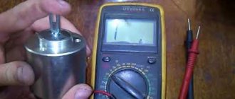
If you were unable to perform such a manipulation, this check did not produce any results, then you will have to remove it and deal with it. Before checking the relay, it must be cleaned of various contaminants. Next, connect the starter to the battery. We connect the positive contact of the battery to the relay output, and the negative contact to its body. As a result, a click should occur and the gears should begin to move. This way we know that the relay is working properly. If this operation does not produce results, then the relay must be repaired yourself or purchased a new one. The cost of the relay is not high. If you buy a new one, do not forget to buy the same one (go to the store with the old relay).
After checking the relay, I recommend checking the starter itself. There is a terminal in the place where the relay was; you need to connect the positive alligator clip from the battery to it, and the negative one to the housing. If the gear works, then the reason is in the relay. The second element that may cause poor starter performance is its armature.
The fact is that in a situation where the bendix rotates very slowly, and the battery is fully charged, it is necessary to remove the armature. Next, you need to check the housing winding and the winding short circuit - these are the main reasons for the failure of the starter armature. To check the functionality of this element, you need to use a tester and check the voltage between the windings and the rotor housing. The tester should show at least a million ohms, or even more. If the data is lower, the anchor needs to be replaced.
From my experience I know that checking the bendix, brushes and windings play an important role in the good performance of the machine. If the relay does not work, then it is necessary to check the brushes and the winding. To check, you need to use a regular light bulb (12 Volts) with two wires that are connected to the brush holder and to ground. When checking, the starter must be connected to the battery. If the lights come on, this means that the brushes are faulty. In the same way it is necessary to check the winding.
It is important to remember that if several starter elements break down at the same time, it is advisable to purchase a new one rather than try to replace one part at a time.
If one part fails, then it needs to be replaced. The new part must be identical to the part being replaced. It is not advisable to purchase analogues; this may lead to undesirable consequences in further work.
Video “Checking current leakage”
The recording shows how you can check at home whether there is a current leak on a JEEP car.
How it works
Now a little about the nuances of interaction between the armature, bendix and retractor relay, as well as other components. In fact, there are conditionally three stages of starter operation:
- First, the drive gear and starter ring of the flywheel used are connected;
- Next, the starter itself starts;
- At the third stage, disconnection occurs.
The starter has a very short cycle of operation, since in the future it does not take any part in the process of driving the car. This is not cruise control. The starter has one job - to start the engine. After that, it is free until the next launch.
But let's look at the work in more detail, as we did when we examined the principle of operation of the clutch. Everything looks like this step by step:
- We turn the key in our car ignition;
- The ignition is turned to the starting position;
- The current follows an electrical circuit from the battery to the lock;
- Next, the current is transferred to the traction solution;
- It is at this stage that our bendix engages with our flywheel;
- In parallel with the movement and engagement of the gear, the chain is closed;
- The voltage goes to the electric motor;
- The engine starts;
- The revolutions of the motor itself exceed the revolutions of our starter;
- The clutch separates the electric motor shaft and the drive gear.
All. This completes the operation of the device. The starter is needed literally for a few seconds if everything is working properly in the car. But this fact does not in any way diminish the value of such a device.
Kinds
I think the scheme is clear to you. But it is also worth noting the fact that certain varieties of this element exist. Starters can be divided into 2 types:
- gear;
- gearless.
If these are diesel internal combustion engines or high-power motors, the use of a gear starter is relevant here. It is not planetary. Such an element is capable of several times increasing the voltage that passes through it, thereby increasing the torque.
Geared devices have their advantages:
- high level of efficiency;
- increased efficiency;
- less current consumption during cold start;
- modest size;
- excellent performance;
- best operating parameters;
- effective starting even when the battery charge drops.
And gearless ones differ in that they make direct contact with rotating gears.
A starter without a gearbox has the following advantages:
- simplified design;
- better repairability;
- resistance to increased loads;
- quick engine start.
Everyone can draw the appropriate conclusions for themselves. You decide. Although in many respects the car manufacturer itself has decided for you by installing one or another type of starter on the car.
It’s not like with gearboxes, where when purchasing a car owner decides whether to buy a CVT, a classic manual, or an advanced sequential gearbox.
How to hook up a button to the starter via a relay and connect
Today, drivers of old cars often want to see a convenient button on the instrument panel that can easily activate the starter. They want such modernization not only for aesthetic purposes, but also for purely practical ones. We will learn from the article how to connect a button to the starter via a relay.
Contact vulnerability
In cars manufactured more than ten years ago, the starter wires are always connected directly to the ignition switch contacts. The engine starts only after the driver turns the ignition key to the extreme position.
This option for connecting the starter is simple and effective. But contacts are always a problem. Moreover, when the starter device is activated, a huge amount of voltage is generated, causing sparking. Where there is a spark, the contacts burn out, oxides accumulate on them, etc. As a result of this, over time, problems arise with starting the engine; motorists are looking for alternative ways to turn on the starter, including directly from the battery.
How to connect a starter via a relay
As you know, in cars of recent years of production, which do not have a button, an additional relay is provided that controls the starter. In this way, the lock contacts are relieved, which now bear less of a load.
- Systems with a separate relay are more reliable because they last longer.
- The ignition switch contacts also “live” much longer.
- An additional relay can always be upgraded.
How to connect a button to the starter
However, the topic of this article is connecting the starter via a button connected to the same relay. How can this be accomplished?
Connecting a button in a car where there is no additional relay
First of all, you should find the contacts responsible for turning on the starter. Then integrate them with the button.
The modernization algorithm generally looks like this:
- The plastic trim under the steering wheel is disassembled;
- There is a connector connected to the ignition switch contacts (as a rule, this connector has locking tabs);
- Press the tabs to release the connector and pull it out.
As a rule, on older cars, after inspecting the connector, two cables with a large cross-section are found. The red one is responsible for controlling the starter.
Note. You can check whether the wiring is really responsible for controlling the starter like this. Turn the ignition key all the way, short-circuit both wires from the removed connector. If the starter turns on, then that's what they are.
- The button is placed in a place convenient for the driver;
- The found wires are connected to it.