Methods for checking the camshaft sensor
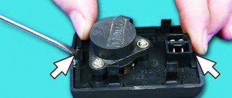
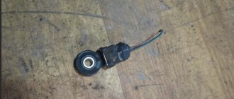
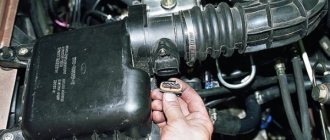
Before testing the sensor using a multimeter or other electronic tools, you must check its mechanical integrity. In particular, it is installed in a housing with an O-ring, ensuring its secure fastening. We need to check its condition. It would also be useful to check the integrity of the sensor body, whether there are cracks or other damage on it. It is advisable to check the drive disk to see if the teeth are damaged or if there are metal shavings on the sensor body or nearby.
On the Internet you can find information that supposedly the DPRV can be determined to work by simply checking its magnetic properties. In particular, bring a small metal part to its end (the working sensitive part), which should “stick” to the sensor. In fact, this is not the case, and a non-working DPRV may or may not have magnetic properties. Accordingly, verification must be performed using other methods.
There are two main ways to test the camshaft position sensor - using an electronic multimeter and using an oscilloscope. The first method is simpler and faster, but the second is more accurate and provides more diagnostic information.
Checking the camshaft sensor with a multimeter
To check the DPRV, dismantling is necessary. This is not difficult to do; you just need to disconnect the contact group of wires from it and unscrew the fastening bolt. You will also need a small metal object (ferrous metal so that it is magnetic) to test.
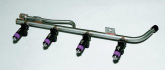
Connection diagram for checking phase sensor 21110-3706040
Connection diagram for checking phase sensor 21120-3706040
The algorithm for checking the sensor with a multimeter is as follows:
- Take a multimeter and switch it to the DC voltage measurement mode in the range up to 20 V (depending on the specific multimeter model).
- Disconnect the “chip” from the sensor by unclipping the latch.
- Remove the sensor from its mounting location.
- On the “chip” of the sensor 21110-3706040 of a VAZ car (and on many others), contact “A” corresponds to ground, contact “C” is the positive wire, comes from the control relay, contact “B” is the signal wire (middle). For sensor chip 21120-3706040, contact “A” corresponds to ground, contact “B” is the positive wire from the control relay, contact “C” is the signal wire.
- Check the presence of power on the chips. To do this, you need to turn on the ignition on the car (but do not start the engine) and do this with a multimeter. If there is no power to the chips, then you need to look for the reason. This could be faulty wiring (insulation damage, broken wires), failure of the control relay, or a glitch in the electronic control system (ECU).
- Next, you need to connect the sensors for testing according to the diagrams shown in the figure.
- Apply a voltage of 13.5±0.5V to the sensor (although less is allowed, for example, 12...12.5 Volts from the battery).
- If, when power is applied to the sensor, the voltmeter detects a lack of voltage on the sensor, then this indicates either a breakdown of the sensor itself, the test can be completed and you can prepare to replace the sensor with a new one.
- Measure the voltage between the positive and signal contacts. It must be equal to at least 90% of the supply voltage (that is, if the supply voltage is 12 Volts, then the voltage at the signal contact must be at least 10.8 Volts).
- Bring a metal object prepared in advance to the end of the sensor (its signal part). Re-measure the voltage at the signal contact. It should be no more than 0.4 Volts. Remove the plate - the voltage value should be restored to 90.100% of the supply. If there are any deviations during the verification process, it means that the sensor has failed and must be replaced.
Checking the DPRV using an oscilloscope
An electronic oscilloscope helps to understand how the camshaft position sensor works and whether it produces pulses at all. Usually they use a so-called electronic oscilloscope, that is, simply a simulator program installed on a laptop or other similar device. You need to connect to the camshaft sensor and take an oscillogram from it. Ideally, there should be a smooth comb diagram with one drop-out peak that corresponds to the rapper passing through the sensor. If the oscillogram has a different shape, additional verification is needed.
When diagnosing the camshaft sensor of Nissan cars (in particular, Nissan Almera) with an oscilloscope, the shape of the oscillogram will be different. It will not be smooth, but in the form of 3 impulses, then a space, then 4 impulses - a space, 2 impulses - a space and one impulse - a space. For engines from this automaker, this feature is the norm.
How to make sure the DPRV is working?
The easiest way to check the camshaft sensor is to connect a car scanner or a computer with an installed program corresponding to the make of the car to the diagnostic connector of the car. If the element is faulty, then after starting the engine the device will display the following error codes:
- P0340 – there is no signal from the camshaft position detector;
- P0341 – valve timing does not coincide with the compression/intake strokes of the cylinder-piston group;
- P0342 – the signal level in the electrical circuit of the DPRV is too low;
- P0343 – the signal level from the meter exceeds the norm;
- P0339 – an intermittent signal is received from the sensor.
Since the vast majority of car enthusiasts do not have scanners and laptops with software at their disposal, a more affordable method is practiced - checking with a digital multimeter. Diagnostics is carried out in 3 stages:
- Visual inspection of the wiring and continuity of the circuit for breaks.
- Measuring the outgoing current at the control contact of the DPRV.
- Testing functionality by approaching a metal object.
At the first stage, you need to ensure the integrity of the wiring and reliable contact of the connecting block. Carefully inspect the supply cables for kinks, cracks and melted insulation. Testing the current-carrying conductors and searching for a break is performed with the same multimeter. Don't forget to clean the connector contacts from oxidation.
After checking the electrical wiring, proceed to diagnosing the camshaft sensor itself. Instead of standard alligator clips on the tester, you need to use wires with needles so that you don’t have to be tricky with connecting to the connecting block. Diagnostic work is carried out in the following order:
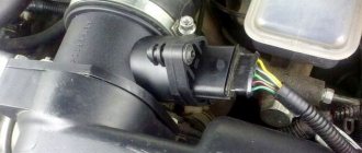
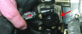
- Open the hood and look for the DPRV on the cylinder head. Usually the element is placed on the end of the engine or the side wall of the cylinder head next to it.
- Using the vehicle's electrical diagram or data for a specific sensor model, determine the location of the two power contacts and the third wire going to the controller.
- Turn on the ignition and measure the voltage between the vehicle ground and the control contact of the element (on VAZ cars this is the middle wire, marked “C”). Normal multimeter readings are at least 90% of the supply voltage, that is, 12 * 0.9 = 10.8 V.
- If the obtained values are below normal, the sensor is faulty and must be replaced. Otherwise, perform the third stage of verification.
For final diagnostics, the part will have to be removed from the engine. Typically, the element is inserted into a hole in the cylinder head and secured with one bolt. Unscrew it, remove the DPRV and wipe off the engine oil. Do not disconnect the block with wires.
After connecting the multimeter to the middle contact and ground of the car, turn on the ignition again. Bring a steel object (for example, an open-end wrench) close to the end of the element, monitoring the display readings. A working sensor should respond to the approach of metal with a voltage drop to 0.2–0.4 V.
If checking the camshaft sensor with an iron object does not change the tester readings, the DPRV should definitely be changed. When purchasing a new part, keep one thing in mind: even original spare parts can be sold without a thin O-ring. You will have to find and buy it separately or use an old seal, provided that the material is not cracked or “dull.”
Signs of a faulty phase sensor
If the phase sensor fails completely or partially, the electronic control unit forcibly switches the engine to paraphase fuel injection mode. This means that the timing of fuel injection is carried out according to the readings of the crankshaft sensor. As a result, each fuel injector injects fuel twice as often. This ensures that a fuel-air mixture is formed in each cylinder. However, it is not formed at the most optimal moment, which leads to a drop in engine power, as well as excessive fuel consumption (albeit small, although this depends on the specific engine model).
Symptoms of a faulty phase sensor are:
- fuel consumption increases;
- the toxicity of exhaust gases increases, the smell of exhaust gases will be felt, especially if the catalyst is knocked out;
- the engine begins to operate unstably, most noticeably at low (idle) speeds;
- the acceleration dynamics of the car, as well as the power of its engine, are reduced;
- the Check Engine warning light is activated on the dashboard, and when scanning errors, their numbers will be associated with the phase sensor, for example, error p0340;
- at the moment the engine starts in 3...4 seconds, the starter spins the engine “idling”, after which the engine starts (this is due to the fact that in the first seconds the electronic control unit does not receive any information from the sensor, after which it automatically switches to emergency mode, based on data coming from the crankshaft position sensor).
In addition to the above symptoms, often when the phase sensor fails, problems arise with the vehicle’s self-diagnosis system. In particular, at the moment of starting, the driver is forced to turn the starter for a little more time than usual (usually 6.10 seconds, depending on the model of the car and the engine installed on it). And at this time, self-diagnosis of the electronic control unit occurs, which leads to the formation of corresponding errors and transfer of the engine to emergency operation mode.
Malfunctions of the phase sensor on a car with HBO
It is noted that when the engine is running on gasoline or diesel fuel, the unpleasant symptoms described above do not appear so acutely, which is why many motorists often use cars with a faulty phase sensor for a long time. However, if your car is equipped with gas equipment from the fourth generation and higher (which uses its own “smart” electronics), then the engine will work intermittently, and the driving comfort of the car will sharply decrease.
In particular, fuel consumption will increase significantly, the air-fuel mixture may be lean or, conversely, enriched, and engine power and dynamics will significantly decrease. All this happens due to a mismatch between the software of the electronic engine control unit and the LPG control unit. Accordingly, when using gas-cylinder equipment, the phase sensor must be changed immediately after its breakdown is detected. Using a machine with a damaged camshaft position sensor is harmful in this case not only to the engine, but also directly to the gas equipment and its control system.
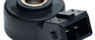
Design
On the VAZ 2110, the camshaft position sensor is made in the form of a cylinder and has an end-mounted operating principle. Its structural elements are:
- plastic case;
- semiconductor wafer;
- secondary converter;
- magnet;
- current-carrying elements.
The DPRV connector has three contacts:
- constant power supply;
- transmission of the read signal to the control unit;
- weight.
Engines on which two camshafts are installed, and the gas distribution mechanism consists of sixteen valves, also have one camshaft position sensor of the same design.
What is a phase sensor used for?
To understand possible malfunctions of the phase sensor, it makes sense to briefly dwell on the question of what it is, as well as the principle of its design.
Thus, the main function of the phase sensor (or DF for short) is to determine the position of the gas distribution mechanism at a specific point in time. In turn, this is necessary so that the electronic engine control unit (ECU) gives the command to inject fuel at a certain point in time. In particular, the phase sensor determines the position of the first cylinder. The ignition is also synchronized. The phase sensor works in conjunction with the crankshaft position sensor.
Phase sensors are used on engines with distributed phased injection. They are also used on engines that use a variable valve timing system. In this case, separate sensors are often used for the camshafts that control the intake and exhaust valves.
The operation of modern phase sensors is based on the use of a physical phenomenon known as the Hall effect. It lies in the fact that in a semiconductor wafer through which an electric current flows, when it moves in a magnetic field, a potential difference (voltage) arises. A permanent magnet is placed in the sensor body. In practice, this is implemented in the form of a rectangular plate of semiconductor material, to the four sides of which contacts are connected - two input and two output. Voltage is applied to the first, and a signal is removed from the second. All this happens on the basis of commands coming from the electronic control unit at a specific point in time
There are two types of phase sensors - slot and end. They have different shapes, but work on the same principle. So, on the surface of the camshaft there is a mark (another name is a benchmark), and during its rotation, a magnet included in the sensor design records its passage. A system (secondary converter) is built into the sensor body, converting the received signal into information “understandable” for the electronic control unit. End sensors are designed in such a way that there is a permanent magnet at their end, which “sees” the passage of a benchmark near the sensor. In slot sensors, the use of the letter “P” shape is implied. And the corresponding reference point on the distribution disk passes between the two planes of the housing of the slotted phase position sensor.
In injection gasoline engines, the master disk and the phase sensor are adjusted in such a way that a pulse from the sensor is generated and transmitted to the ECU at the moment the first cylinder passes its top dead center. This ensures synchronization of fuel supply and the moment of spark supply to ignite the air-fuel mixture. Obviously, the phase sensor has a direct impact on the operation of the engine as a whole.
Repair
Before checking the DPRV or before starting any independent actions, you need to familiarize yourself with the connection diagram for the VAZ 2110 camshaft sensor, as well as the features of its installation in the engine body.
The type of action performed depends on what signs of malfunction have been identified:
- if there is visible mechanical damage to the wiring or exposure of live parts, it must be replaced, but repairs in the form of re-insulation of the wires are also possible;
- If the sensor is mechanically damaged, it must be replaced. It is not recommended to repair or disassemble it;
- if the connector is dirty, it is necessary to reconnect with a visual inspection and cleaning of the electrical contacts;
- Wear of the connection connector requires its maintenance or replacement of the sensor. Maintenance consists of ensuring a tight fit of the connected parts;
- When checking the electrical wiring or sensor with a voltmeter and identifying deviations, it is necessary to replace the faulty element. When connecting the voltmeter probes to the electrical power contacts, the sensor resistance should not be lower than 550 Ohms or higher than 750 Ohms;
- If an internal malfunction of the sensor is detected during computer diagnostics, it must be replaced.
Replacing the DPRV is carried out by disconnecting it, dismantling the faulty one, installing a new one and reconnecting the power connector.
It is important to note that after performing any actions aimed at eliminating identified faults, it is necessary to recheck the engine operation.
The operating manual does not recommend disabling the sensor yourself and further operating the vehicle.
Description of the procedure for replacing the timing belt VAZ 2110, (2112) 16 valves
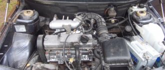
Former flagship of the Russian automobile industry VAZ 2110 with a 1.5 16 valve engine. Scheduled replacement of the timing belt 30,000 km after the last replacement. The autopsy showed that if they had not changed it today, then tomorrow there would have been more work for our mechanic. In general, we recommend that all customers check the condition of the belt at least once every 5,000, or once a year. But knowing the quality of our spare parts, more often is better. On this engine, if the belt breaks, almost all the valves bend. The article is also relevant for VAZ 2112))
We look, remember and don’t let it get to that point.
The patient became five millimeters narrower and generally looked very bad. We send him to the honor board.
And here is the hero of the occasion himself.
We remove the absorber and power steering reservoir so that they do not interfere in the future.
We loosen the bolt by seventeen, the tension roller of the service belt and remove the last one. It will not be possible to remove it completely because the engine mount is in the way. If the belt requires replacement, you will have to unscrew the engine mount.
Remove the tension roller. We unscrew the bolts securing the upper protective cover; they are hexagonal.
Remove the right wheel, plastic mudguard and drain the antifreeze.
We see the crankshaft pulley. Using its bolt, clockwise, rotate the crankshaft until the marks on the camshaft pulleys and the timing belt protective cover match.
Markings on the left exhaust camshaft. The mark on the protective cover is highlighted in red.
Likewise for the intake camshaft. He's on the right. Its pulley has an inner ring for the phase sensor, so it is very difficult to mix up the pulleys.
Remove the crankshaft pulley. Let's lock the crankshaft with the help of a friend. We put him in the car and force him to turn on fifth gear and press the brake all the way. And at this time, with a slight movement of your hand, unscrew the crankshaft pulley bolt. Remove it and the lower protective cover.
We see that the mark on the sprockets and the slot on the ebb of the crankshaft cover coincide.
Loosen the seventeen bolts of the tension and idler pulleys and remove the timing belt. Then the videos themselves. We change them anyway.
We lock and unscrew the camshaft pulleys and remove them. Remember that the right camshaft has a pulley with an inner ring for the phase sensor. The picture should look like this.
We unscrew everything that holds the protective plastic cover and remove the latter. Unscrew the three bolts holding the pump. They are hexagonal.
The pump for a sixteen valve engine is slightly different from the usual for an eight valve engine. It has a small threaded ear for attaching the protective casing.
Lubricate the gasket with a thin layer of sealant and put the pump in place. Tighten the fastening bolts. We put the protective cover in place. We make sure that he sits in his place, otherwise he will rub the belt. If everything is in order, tighten everything that holds it and install the camshaft pulleys and new rollers.
We check that the marks on the camshafts and crankshaft match. We install a new timing belt. If there are no directional arrows, put it so that the inscription is read from left to right.
The right, or descending, branch of the belt should be tight. You can turn the right camshaft clockwise a few degrees, put on the belt and turn it back. In this way we will stretch the descending branch. The tension roller has two holes for a special key. You can find it in any auto store. The issue price is 60 rubles. To tension the timing belt, insert a special key and turn the roller counterclockwise. Since there is a lot of controversy about tensioning the timing belt, we will write this: a tensioned belt should not have a sag between the camshafts of more than 5 mm when pressed and 7 mm on the longest branch (specially experimented). Remember: an overtightened belt reduces the service life of the pump, and an undertightened belt can lead to cylinder head repair. (photo below)
We check all the marks. We turn the crankshaft two turns and check the marks again. If the pistons and valves do not meet and the marks coincide, then accept my congratulations. Then we put everything back in place in the reverse order of removal. Don't forget to tighten the bolts. We tighten the service belt roller with the same wrench as the timing belt tension roller. Fill with antifreeze and start the car. We wish the belt many years of service, but don’t forget to check it periodically; after all, it was made in Russia.
Methods for checking the camshaft sensor
Before testing the sensor using a multimeter or other electronic tools, you must check its mechanical integrity. In particular, it is installed in a housing with an O-ring, ensuring its secure fastening. We need to check its condition. It would also be useful to check the integrity of the sensor body, whether there are cracks or other damage on it. It is advisable to check the drive disk to see if the teeth are damaged or if there are metal shavings on the sensor body or nearby.
On the Internet you can find information that supposedly the DPRV can be determined to work by simply checking its magnetic properties. In particular, bring a small metal part to its end (the working sensitive part), which should “stick” to the sensor. In fact, this is not the case, and a non-working DPRV may or may not have magnetic properties. Accordingly, verification must be performed using other methods.
There are two main ways to test the camshaft position sensor - using an electronic multimeter and using an oscilloscope. The first method is simpler and faster, but the second is more accurate and provides more diagnostic information.
Checking the camshaft sensor with a multimeter
To check the DPRV, dismantling is necessary. This is not difficult to do; you just need to disconnect the contact group of wires from it and unscrew the fastening bolt. You will also need a small metal object (ferrous metal so that it is magnetic) to test.
Connection diagram for checking phase sensor 21110-3706040
Connection diagram for checking phase sensor 21120-3706040
The algorithm for checking the sensor with a multimeter is as follows:
- Take a multimeter and switch it to the DC voltage measurement mode in the range up to 20 V (depending on the specific multimeter model).
- Disconnect the “chip” from the sensor by unclipping the latch.
- Remove the sensor from its mounting location.
- On the “chip” of the sensor 21110-3706040 of a VAZ car (and on many others), contact “A” corresponds to ground, contact “C” is the positive wire, comes from the control relay, contact “B” is the signal wire (middle). For sensor chip 21120-3706040, contact “A” corresponds to ground, contact “B” is the positive wire from the control relay, contact “C” is the signal wire.
- Check the presence of power on the chips. To do this, you need to turn on the ignition on the car (but do not start the engine) and do this with a multimeter. If there is no power to the chips, then you need to look for the reason. This could be faulty wiring (insulation damage, broken wires), failure of the control relay, or a glitch in the electronic control system (ECU).
- Next, you need to connect the sensors for testing according to the diagrams shown in the figure.
- Apply a voltage of 13.5±0.5V to the sensor (although less is allowed, for example, 12...12.5 Volts from the battery).
- If, when power is applied to the sensor, the voltmeter detects a lack of voltage on the sensor, then this indicates either a breakdown of the sensor itself, the test can be completed and you can prepare to replace the sensor with a new one.
- Measure the voltage between the positive and signal contacts. It must be equal to at least 90% of the supply voltage (that is, if the supply voltage is 12 Volts, then the voltage at the signal contact must be at least 10.8 Volts).
- Bring a metal object prepared in advance to the end of the sensor (its signal part). Re-measure the voltage at the signal contact. It should be no more than 0.4 Volts. Remove the plate - the voltage value should be restored to 90.100% of the supply. If there are any deviations during the verification process, it means that the sensor has failed and must be replaced.
Checking the DPRV using an oscilloscope
An electronic oscilloscope helps to understand how the camshaft position sensor works and whether it produces pulses at all. Usually they use a so-called electronic oscilloscope, that is, simply a simulator program installed on a laptop or other similar device. You need to connect to the camshaft sensor and take an oscillogram from it. Ideally, there should be a smooth comb diagram with one drop-out peak that corresponds to the rapper passing through the sensor. If the oscillogram has a different shape, additional verification is needed.
When diagnosing the camshaft sensor of Nissan cars (in particular, Nissan Almera) with an oscilloscope, the shape of the oscillogram will be different. It will not be smooth, but in the form of 3 impulses, then a space, then 4 impulses - a space, 2 impulses - a space and one impulse - a space. For engines from this automaker, this feature is the norm.
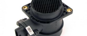
Purpose of the DPRV
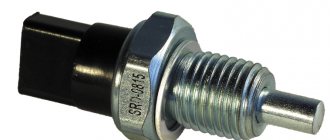
Such a device is based on the electromagnetic principle of operation and is used to carry out commands from the vehicle control and testing complex. The importance of the device parameters lies in the fact that without them there is no way to synchronize the car’s ignition system and the correct operation of the engine injectors, i.e. set the desired concentration of the air-droplet mixture supplied to the engine cylinders. Finding this sensor is easy. It is located on the high tide near the generator drive pulley.
VAZ-2112 sensors 16 valves and their location: diagram, photo, video
Replacing the temperature sensor on a VAZ 2110 in 5 minutes!
The efficient operation of the injection engine is ensured by a set of sensors. They all connect to the ECU. Lada hatchbacks of the 2112 family were produced only with injection engines, and two varieties of these internal combustion engines are 16-valve. We will talk about them further. All VAZ-2112 sensors, their location and appearance will be shown in the photo. The excess oil pressure sensor, which is not connected to the ECU, is shown in the video.
Understanding the oxygen sensor
It is necessary to determine the sensor articles not by the engine model or even by Euro standards, but only by the ECU unit.
The number of oxygen sensors can be two or one - it all depends on environmental standards. AvtoVAZ also used two types of sensors - 0 258 005 133, 0 258 006 537 (BOSCH part numbers). The first of them are compatible with BOSCH M1.5.4, MP7.0 and January 5.1 controllers. Newer sensors were connected to the BOSCH M7.9.7 ECU (January 7.2). The two different types of sensors differ even in appearance.
The ECU unit in “Dozens of VAZs” is located under a plastic cover. It is located near the front passenger's foot.
The red arrow marks the first, that is, the main sensor. The top photo corresponds to engine 21124 (1.6 l).
VAZ-21120 engines (1.5 l) could meet the Euro-3 standard, and then an “extended” catalyst was welded behind the main sensor. The second sensor was located behind it, that is, behind the “can”. Let's clarify:
- The Euro-2 standard corresponds to a design with one sensor (main);
- During the transition to Euro-3 standards, a second sensor was added (blue arrow).
By the way, the 24th engine can meet Euro-4 standards.
Which VAZ engines have a phase sensor
Main set of sensors for 16-valve VAZ-2112 engines
The ECU must control many parameters at once
The most important information will be the position of the crankshaft. You can turn off all sensors except the DPKV, and this will not lead to the engine stopping. Let's list all the elements one by one:
Let's list all the elements one by one:
Let's take a look at how all the elements look in real life. Shown are pictures of VAZ-2112 sensors (16-valve internal combustion engine).
Everything said above is true for two engines at once - for units 21124 and 21120 (1.6 and 1.5 l).
You cannot unscrew the DTOZH sensor without draining the coolant. And to disconnect the sensor means to disconnect the connector, but not to dismantle the sensor itself.
Where is which sensor located - engine compartment diagram
Let's look at another picture.
It is important to understand where the following elements are located:
The location of the phase sensor is indicated in the previous chapter.
How to check Niva Chevrolet phase sensor
Never unscrew the speed sensor. It will be difficult to install it in a way that maintains a seal.
Articles
For oxygen sensors, the designation 21120-3850010 was first used. Then an article appeared with the numbers 1118 (see photo). It appears to be a new type of sensor. It will be easier to use BOSCH articles.
We list the article numbers of the remaining sensors:
- Mass air flow sensor (21124 or 21120): 21083-1130010-01, -10, -20;
- Mass air flow sensor (motor 21120 with ECU January 4.1): 2112-1130010, -01;
- DPDZ: 2112-1148200;
- РХХ: 2112-1148300-02;
- DPKV: 2112-3847010, -01, -03, -04;
- DTOZH: 2112-3851010, -01, -02, -05;
- Speed sensor: 2110-3843010-13, -18;
- DPRV: 2112-3706040, -02, -03;
- DD: 2112-3855020, -01, -02, -03;
- Oil pressure sensor: 2106-3829010, -01, -02;
- Antifreeze level sensor: 2110-3839310-10, -11, -12, -13, -14;
- Coolant temperature indicator sensor: 2101-3808600, -02, 2106-3828010.
The last three sensors are not connected to the ECU. However, a rough road sensor (2123-1413130) can be connected. It affects the operation of the engine, although it is attached to the body.
Engines with ECU January 4.1 do not have oxygen sensors.
In general, on VAZ-2112 hatchbacks, sensors may be different from those indicated in the list. But then we are talking about an 8-valve engine. And everything that we indicated applies to 16 valves, here is a diagram of this engine.
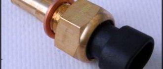
Checking the coolant temperature sensor VAZ 2110
Homemade test stand
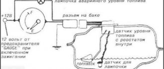
Below is a diagram that, once assembled, can be tested. It appears that the sensor could have been left on the engine. But not only the electrical part is important, but also the ability to remove and bring up the steel plate.
Test stand
So, taking an E battery (12 Volts) and two voltmeters, we assemble the circuit. Next we run the test:
- On the “free sensor”, the voltmeter V1 will show a voltage of 0.4 V (or less);
- If you install a plate from a transformer in the slot, the voltage will change to 10.8-11.5 V.
Plate dimensions: 20x80x0.5mm or larger. If at “step 1” the voltage was higher than specified, the sensor is faulty. At “step 2”, on the contrary, the value should exceed V2*0.89.
We did not come up with the stand layout, but took it from the information letter. On different VAZ-2112 engines, the phase sensor is checked differently (see photo).
Screenshot of the VAZ “65-2003-I” document
For those who don't understand everything
The rectangle shown in the diagram is a resistor. Resistance is 680 Ohms, power is any. The power source can be not only a battery, but also a 12-volt adapter.
Element E can be an LATR with a rectifier. Then, firstly, try not to exceed the voltage, and secondly, connect the ground (pin 1) to the “ground” tap of the LATR.
Instead of the numbers 2112-3706040, the article number 21120-3706040 is found. Both designations are correct. You can also find an article with the numbers -00, -01, -02... This is how the manufacturer is designated: 01 and 03 - “SOATE”, 00 - “Autoelectronics”, etc.
Parts with article number 2112-3706040-04
Recently, flexible lead sensors have been launched. The length of the wires is 15 cm. So far there is nothing like this in retail. But the article numbers remained the same - 2112-3706040-XX.
Replacing the RV position sensor
The sensor replacement algorithm is as follows:
- With the engine not running, disconnect the negative terminal from the battery.
- Disconnect the “chip” from the camshaft position sensor (as when checking).
- Depending on the vehicle model, it is necessary to remove parts that prevent access to the sensor. For example, on modern cars like the Lada Vesta, it is necessary to remove the bracket for auxiliary units.
- Using a wrench, unscrew one or two mounting bolts, depending on the type of fastening. The size of the wrench can be different, usually for VAZs it is a 10 mm wrench.
- After dismantling the mount, you must similarly remove the sensor from its seat.
- Installing a new sensor is performed in reverse order.
- Connect the negative terminal to the battery.
When purchasing a new camshaft position sensor, you need to pay attention to the condition of its O-ring. It is usually sold separately
When changing the sensor, it is advisable to also change the O-ring, since over time it wears out and loses its elasticity. You can use an old ring only in case of emergency, when it is not possible to buy a new one.
Conclusion
The camshaft position sensor is a simple but important device in the engine, and the normal functioning of the engine depends on its operation. Therefore, if signs of its failure are identified, it is advisable to carry out the appropriate diagnostic procedures as quickly as possible.
They are simple, and even a novice car owner with no experience can handle them. The same goes for replacing it. The price of a phase sensor for VAZ cars as of winter 2022 is about 400 rubles.
The operating principles of the phase sensor and speed sensor are similar. The sensor pulses the circuit to ground when the camshaft pin (phase sensor) or the steel elements of the drive disk (speed sensor) passes near its end. We show the test using the example of a phase sensor.
1. With the ignition off, disconnect the engine control system wiring harness block from the phase sensor. The wiring harness block terminals “A”, “B” and “C” are marked on the block body.
2. To check the sensor’s power circuit, connect the tester probes to terminals “B” and “A” of the wiring harness block. When the ignition is turned on and within 10 seconds after it is turned off, the voltage should be equal to the on-board network voltage.
3. Otherwise, check the serviceability of the circuits (open circuit and short to ground) between terminal “B” of the wiring harness block and terminal “45” of the controller (“+” power supply), as well as between terminal “A” of the block and the grounding point.
4. If the circuits are working properly and there is no voltage, the controller is faulty. We connect the tester probes to terminals “C” and “A” of the wiring harness block.
When the ignition is on (and in the absence of a phase sensor signal), the controller, through its internal resistor, must output on-board voltage to terminal “C” of the wiring harness block.
5. Otherwise, check the serviceability of the circuit (open and short to ground) between terminal “79” of the controller and terminal “C” of the wiring harness block.
6. To check the phase sensor, dismantle it and connect the wiring harness block to the sensor. From the side where the wires enter the block, we insert two pieces of wire into its sockets corresponding to terminals “A” and “C” so that contact appears between them and the tips of the wires. We connect the tester probes to the pieces of wire. After turning on the ignition, we bring a steel rod (for example, a screwdriver) several times to the end of the sensor.
7. In this case, for a working sensor, the device should record abruptly changing voltage values.
8. We check the speed sensor and its circuits in the same way. The engine control system wiring harness connector connected to the speed sensor has pin numbering “1”, “2” and “3”. Pin “1” of the wiring harness block is supplied from the main relay with a voltage equal to the voltage of the vehicle’s on-board network. The signal from the speed sensor is fed through terminal “2” of the block to terminal “59” of the controller. Pin “3” of the block is connected to ground.
- Kia sportage 3 does not turn the starter
- Why does the MTZ 82 tractor not start from the starter?
- Subaru Legacy B4 power windows do not work
- Ford explorer 3 fuse diagram
- Mercedes w203 starter turns but does not engage
Changing the oil seal
Below is a step-by-step manual for changing the camshaft oil seal for a VAZ 2110 car. The instructions are relevant for 16- and 8-valve engines. If you notice a new knocking noise coming from the camshaft, then, apparently, you need to disassemble it. Most likely, the knocking will go away after replacing the element. The part itself must be purchased in accordance with the manufacturer's specifications.
As for the characteristics themselves, the component must correspond to the dimensions of the part installed in a given car model. If the specifications are not met, you may have to go to the store for a new oil seal in the midst of repairs.
We change it with our own hands
- First of all, you should dismantle the timing belt of the VAZ 2110.
- Then you will need a "17" wrench. Take the tool and begin to unscrew the screw that secures the toothed disk of the timing pulley. You need to make sure that the pulley does not turn. To do this, you will need to pass a “10” head through the hole in it, which must be put on an extension cord. Engage the nut securing the rear cover of the timing belt drive.
- After this, using a screwdriver, pry up the timing pulley disk and dismantle it. At this moment, be careful: under no circumstances should the toothed disk key be lost. Remove it from its installation location.
- Now, using the same screwdriver, pry up the camshaft oil seal that needs to be replaced and remove it.
- Take a new oil seal and lubricate its edge and installation location with engine fluid. If you do not lubricate the element itself with oil, the knocking may not go away. To install the component you will need a small piece of pipe. The oil seal will need to be pressed in carefully. You will also need a hammer for this.
- Carry out all subsequent assembly in reverse order. Don't forget to align the timing belt correctly.
After completing the repair work, start the engine and check if the knocking noise disappears. If there is no knocking noise, then the whole problem was in the camshaft oil seal.
1. Unscrew the camshaft pulley screw.
2. After this, the toothed pulley itself can be dismantled.
3. Using a screwdriver, pry out the element that needs to be replaced.
4. Lubricate the part with oil and press it into the installation location.
Actually, this completes the procedure for replacing and eliminating camshaft knock. We strongly advise you not to carry out this work yourself if you do not have enough skills. Incorrect tightening of the timing belt and incorrect alignment of this element to the markings can subsequently cause the belt to break. If this happens while driving, the VAZ 2110 engine valves may bend. As you understand, subsequent repairs will cost a pretty penny.
Replacement procedure
If checks show that your element no longer performs its previous functions, you will have to replace it with a new one. This is done quite simply.
Unscrew
You need to follow the sequence of actions, which will allow you to carry out the replacement yourself without unnecessary problems and financial costs.
- Remove the distributor from your car and remove its cover.
- Remove the slider. To do this, you need to pull it up a little.
- Remove the black cover. On the VAZ 2110 it is usually made of plastic.
- Remove the bolt that holds the plug.
- Remove the plug itself.
- Unscrew the mounting bolts that hold the hall sensor plate.
- Remove the fasteners securing the vacuum manifold.
- Remove the retaining ring.
- Remove the rod and corrector from the structure.
- Next you will find a clamp that needs to be pulled apart to remove the wires.
- Now the support plate is removed.
- Two bolts hold the hall sensor. They need to be unscrewed, which will allow you to remove the meter and put a new one in its place. Perform the assembly procedure strictly in the reverse order of dismantling.
If you find primary signs of a malfunction, we strongly do not recommend delaying repairs. Complete the check as quickly as possible.
If the check shows that the meter is faulty, follow the procedure for dismantling it, and also select a quality spare part.
How to check
This device can be checked for malfunction. To do this, you will need a special diagnostic device. It will be impossible to accomplish this in any other way. With its help, a certain procedure is carried out, which consists of several stages.
First, you need to install the upper cylinder of the device so that it hits the dead center. It is also worth paying attention to the location of the sensor, which is responsible for the operation of the crankshaft. It should be directed towards the twentieth tooth.
About the sensor
The Priora uses phased fuel injection. The operating principle of this injection is based on the readings of the phase sensor. The phase sensor receives pulses from the camshaft pulley and supplies them to the computer. In turn, the ECU, receiving these signals, adjusts the fuel injection and distributes it among the phases.
If the phase sensor malfunctions, the engine goes into emergency operation mode, switching fuel injection to pairwise mode, that is, the injectors begin to supply fuel in pairs to cylinders 1 and 3, 2 and 4.
Failure of the DF produces small but very noticeable symptoms that will undoubtedly force you to replace it.
Causes of malfunction
The main reason for the malfunction of the phase sensor is its natural wear, which occurs over time for any part. In particular, due to exposure to high temperatures from the engine and constant vibration in the sensor housing, its contacts are damaged, the permanent magnet may demagnetize, and the housing itself may be damaged.
Another main cause is problems with the sensor wiring. In particular, the power/signal wires may be broken, which is why no supply voltage is supplied to the phase sensor, or a signal does not come from it via the signal wire. It is also possible for the mechanical fastening on the “chip” (the so-called “ear”) to break. Less often, a fuse that is responsible, among other things, for powering the phase sensor may fail (for each specific car it will depend on the complete electrical circuit of the car).