All cars use a large number of different electronics, which increases the level of driver comfort, and is also necessary for the operation of the internal combustion engine and the entire car. As a rule, power circuits cannot be constantly energized, so the ignition switch is used to turn the vehicle control circuits on and off.
In this article we will talk about the ignition switch on a Lada Niva car (2121, 21213, 21214, etc.), namely the reasons for its breakdown, ways to eliminate them, self-replacement and much more.
About the castle
The ignition switch on the Niva is a part that has a mechanical and electrical part. Each part is responsible for specific functions. The mechanical part protects the car from turning on the ignition with another key and increases the car’s protection against theft. The electrical part (contact group) is responsible for closing the power supply and vehicle control circuits.
Each of the parts can fail, which will lead to the inability to start the engine or stop it altogether.
Niva index designations
The wiring diagram may vary slightly depending on the design features of the vehicle.
First, let's look at the index notation:
- VAZ 21213. This index designates a vehicle equipped with a carburetor. The volume of the power unit is 1.7 liters.
- 21214. In VAZ 21214 cars, the scheme involves the use of a similar engine with the same volume. The only difference is that the car is equipped with a fuel injection system.
- There is another model with the index 21213. In VAZ 21213 cars, the electrical circuit includes the same elements, only depending on the year of manufacture, the car can be equipped with a 1.8 liter engine.
- Version 21073. The SUV is equipped with either an injection engine with nozzles or a Solex carburetor engine. One of the features of these cars is a contactless ignition circuit.
- 21215. These SUVs were originally produced for export, so these cars are difficult to find on our roads. It is worth noting that they were equipped with Citroen diesel engines.
At the beginning of the article there is a diagram of the VAZ electrical equipment using the example of the Niva 2121 model. If you are the owner of version 2131 or any other, then there will be a difference in the circuit diagram, but not fundamentally. If we are talking about carburetor engines, then in this case the circuit, as well as the ignition, will not be protected (the author of the video is Nail Poroshin).
Breakdowns
Most often, the contact group fails, since it is made of plastic into which copper contacts are inserted; due to the flow of high currents and weak contact between the brackets, heating occurs. Due to high temperature, the plastic is deformed and damages the contact group.
The mechanical part fails much less often, but it also happens. It becomes damaged due to prolonged use, the springs in the lock sag, the lock becomes loose, which leads to its jamming or the ability to turn it with almost any key, which reduces the car’s protection to zero.
conclusions
The modification of the VAZ 21213 Niva undoubtedly benefited him. The new engine and improved ignition system have made its operation even easier and more confident in harsh conditions.
Of all the car accessories, the most essential one is a wallet.
Much has been written about how timely the first domestic SUV with a monocoque body turned out to be. Even more was expressed by the owners of the Niva car themselves, who practically deified its capabilities. All they needed for operation was the availability of spare parts and instructions for servicing the vehicle.
The popularity of the model is difficult to overestimate - 28 years in service
Differences between ignition switches
The ignition switches on the Niva are different; on the older VAZ 2121, the ignition switch is from the VAZ 2106, and on the Chevrolet Niva, the ignition switch is from the VAZ 2110.
Ignition switch on Niva until 2009. does not have a common connector, and the wires in it are connected separately. Quite often, when people remove the contacts from the lock, they forget their position and this complicates the assembly process, so it is best to mark the wires first, but if you have already removed the wires and now do not know how to connect them, then you can use the picture below indicating the color of the wires and their connections to a specific contact.
This is how it always happens, some little thing pulls behind it quite a chain of events and sometimes even efforts. I was clearing rubble in the garage) and accidentally discovered a steering column from 2110, I don’t remember where it came from, but it doesn’t matter anymore... in general, I decided to install it to the Niva. Since my main car is a Subaru Forester, the ignition switch is more convenient and familiar to me on the right, and there are two steering columns and not three, and I’m tired of making keys for the Niva, why do they make them... from tin, well, and many different usual ones goodies that are not available in Niva. Well, my soul went to heaven)))... for the steering wheel I had to buy an ignition switch 2110 - steering columns, for some reason everyone uses Shniv ones, I took the 08, it’s more convenient for me to switch them (the lever is closer to the fingers, IMHO) - column casing, again I took 2110, when I was picking it up, I was horrified to find out that there are 3 or 4 types of them... p.c. - a new steering wheel (the original one doesn’t fit), well, different switches, toggle switches, wires, male and female, this I have enough good stuff. There’s just a little bit left to do... time, that’s what I’m struggling with... in the end I got to work during the New Year’s boozy holidays. Installing the column itself was not particularly difficult, there is a lot of information on the Internet, so I won’t describe it for a long time... I only encountered one problem when I tried on the column, the steering wheel hit my “teeth”)))... I don’t know what the reason was, but I had to shorten it the driveshaft is 25 mm, but that’s not a problem, so I managed. The lock was also easy, and I connected it quickly, for which many thanks to comrade PowerFire, but then I slowed down. I decided to implement the possibility of the 10th lock, which few people pay attention to, namely the built-in microswitch. I powered it through the “minus” (85) as many as three 4-pin relays, the “plus” was supplied by a permanent one (86). I made one relay turning off the headlights, turning off the headlights on the second, with the ability to force the toggle switch to turn on while parked with the key pulled out (this is implemented in the Forester), and on the third I put the radio. Now when you take the key out of the ignition, you don’t have to make a bunch of gestures, and it’s gone the likelihood of draining the battery when the headlights are on or the lights are on in the parking lot. Give it to me.
The ignition switch in cars of the VAZ family fails from time to time due to weakening of the contact posts or burning of the contacts inside it. It also happens that the cams of a plastic roller are produced. You can disassemble the lock and clean it, but it’s better to just replace it with a new one, considering that it costs pennies compared to imported locks.
But if connecting the wires together did not result in the starter operating (or it did not turn on the first time), check the solenoid relay on the starter. The contact spots on it may also burn out, which will prevent the circuit from closing normally. Alternatively, you can use a screwdriver to short-circuit the two large terminals on the solenoid relay (before doing this, put the car in neutral and use the handbrake). When closed, the starter should begin to spin vigorously. If this happens, remove and change the solenoid relay. If the starter rotates “sluggishly” when it closes, you will have to remove it and check the condition of the brushes.
All operations are performed with your own hands, without the help of car service specialists. Moreover, the price of an ignition switch on a VAZ2106 is up to 100 rubles. To replace it, you will need to know the pinout of the wires coming from it, for which the editors of the site 2 Schemes.ru have prepared a large reference material.
- supplies voltage to the vehicle’s on-board network, closing the circuits of the ignition system, lighting, sound alarm, additional devices and instruments;
- at the driver’s command, turns on the starter to start the power plant and turns it off;
- turns off the power to the on-board circuit, preserving the battery charge;
- protects the car from theft by fixing the steering shaft.
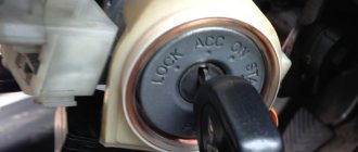
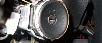
The ignition switch on these cars is located to the left of the steering column. It is fixed directly to it using two fixing bolts. The entire mechanism of the device, except for the upper part in which the keyhole is located, is hidden by a plastic casing.
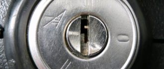
On the visible part of the ignition switch housing, special marks are applied in a certain order, allowing inexperienced drivers to navigate the lock activation mode when the key is in the hole:
- “ ” – a mark indicating that all systems, devices and instruments that are turned on using the lock are turned off (this does not include the cigarette lighter, interior lighting, brake light, and in some cases the radio);
- “I” is a mark informing that the vehicle’s on-board network is powered from the battery. In this position, the key is fixed independently, and electricity is supplied to the ignition system, to the electric motors of the heater and windshield washer, instrumentation, headlights and light signaling;
- “II” – engine start mark. It indicates that voltage is applied to the starter. The key does not lock in this position. If you release it, it will return to the "I" position. This is done so as not to subject the starter to unnecessary loads;
- “III” – parking mark. If you remove the key from the ignition in this position, the steering column will be locked with a latch. It can only be unlocked by inserting the key back and turning it to position “0” or “I”.
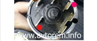
The ignition switch has five contacts and, accordingly, five terminals, which are responsible for supplying voltage to the desired unit. All of them are numbered for convenience. Each pin corresponds to a wire of a certain color:
- “50” – output responsible for supplying current to the starter (red or purple wire);
- “15” – terminal through which voltage is supplied to the ignition system, to the electric motors of the heater, washer, and instrument panel (double blue wire with a black stripe);
- “30” and “30/1” – constant “plus” (pink and brown wires, respectively);
- “INT” – external lighting and light signaling (double black wire).
We carry out the adjustment ourselves
- The first step is to install the cylinder in the correct position. Installation is carried out so that the mark on the pulley is exactly at 0 degrees.
- Set how the slider is positioned. It should be aimed at the first pin in the cylinder.
- Use a strobe light and make sure the ignition is working properly.
- Make the electrical connections in the battery: minus to ground, plus to plus.
- The sensor must be connected to the high-voltage wire on the cylinder. The mark should connect to the crankshaft pulley.
- Start the engine at low speed (up to 800 rpm). Use a stroboscope to illuminate the pulley, and if the mark coincides with the middle mark, then the ignition is set correctly.
- Otherwise, the engine should be turned off and the meter should be loosened. In order to decrease the angle, turn the sensor clockwise; to increase it, turn it counterclockwise. Record and test the calibration again with the ignition on.
- Next, you should perform manipulations with the distribution sensor. Open the lid. Match the stator and rotor mark.
- Start the engine, bring the temperature to 75-80 degrees. When the speed is 50 km/h, sharply press the gas pedal.
- If the ignition was installed correctly, a short-term detonation will occur when you press the gas.
And also interesting: Retractor relay NIVA 21213;
21214 KZATE 57.3708-800-04; 2110-3708805 (gear starter) 6013 - Electrics and Light Next, there are two possible developments of events: early and late ignition. Let's consider solutions for both cases:
- In the case of late ignition, when there is no detonation, you should change the position of the sensor clockwise.
- In the case of early ignition, when detonation lasts longer than necessary, the sensor is rotated counterclockwise.
Niva 21213 can be subject to adjustment of the starting system by the gap at the edges of the valves, if the carburetor is removed, or by the crankshaft speed directly on the car. In the first case, the gap at the location of the lower edge (in the direction of air movement) from the throttle valve is set to a width of 1.1 mm.
It is adjusted with a screw that has a 0.7 cm hexagon on the head and a slot from the shank. This operation is carried out with the cam lever turned counterclockwise from the starting system control (all the way). In the same position, the gap at the lower edge of the air damper is set to 3 mm using a screw in the cover from the diaphragm mechanism in the starting system (you need to loosen the lock nut).
The principle of powering a carburetor engine Adjusting the Niva starting system directly in the car saves time: You need to remove the air filter from the engine, pull the control lever towards you from the air damper, and start the engine. When the air damper is forced to open (by touching a flat screwdriver to a third of its full angle of rotation) using a screw (next to the lever on the axis from the throttle valve from the first chamber), the initial rotation speed is set to 2.08.mar.0 thousand.
If you have a gas analyzer, then the carburetor adjustment in the starting system part can be done based on the amount of CO (carbon monoxide) in the exhaust gases. If, with the choke control lever fully extended, the gas rate is 8%, then everything is in order. If there is less gas than this value, then the screw on the cover of the diaphragm mechanism is tightened; if there is more, it is unscrewed and repeated measurements are taken.
It is necessary to adjust the idle speed of the Niva 2121 so that there is less carbon monoxide in the exhaust gases and so that the engine runs stably. At service stations, such work is carried out with gas analyzers on the MV. In the garage, adjustments can be made using the tachometer.
Pinout of lock VAZ-2108, VAZ-2109, VAZ-21099
Pinout according to the old type
Pinout of the VAZ-2109 ignition switch with unloading relay:
- comes +12V in position I, II, III (parking)
- comes +12V in position I, II, III (parking)
- comes +12V in position III (parking)
- position I, +12V goes out after turning on the ignition (contact 15/2), disappears at start (II);
- position I, +12V goes to the starter (pin 50);
- position I, +12V goes away after turning on the ignition (pin 15), does not disappear when starting II;
- +12V comes from the battery (pin 30);
- comes +12V constantly.
New pinout type
Pinout of the new VAZ-2109 ignition switch:
- comes +12V constantly
- comes +12V constantly
- +12V arrives after turning on the ignition (pin 15), does not disappear when starting II;
- +12V arrives after turning on the ignition (contact 15/2), disappears at start (II);
- position I, +12V goes to the starter (pin 50);
- +12V arrives after turning on the ignition (pin 15), does not disappear when starting II;
- +12V comes from the battery (pin 30);
- comes +12V constantly.
Maintenance Tips
Installing a start/stop button instead of the ignition switch: do it yourself
The factory instructions require troubleshooting the ignition system in the following sequence:
- From the ignition switch (terminal 15), connect the wire to the coil (terminal +B) to a test lamp;
- Connect its negative terminal to ground;
- Turn on the ignition - turn the key in the lock to position “II”;
- If the control lamp lights up, then the circuit is working. If not, look for damage to the wire;
- With the ignition on, pull out the central wire from the coil from the distributor;
- Bring its metal tip to the cylinder block so that a gap of 3-4 mm forms between them;
- Turn on the starter for a few seconds;
- If the spark jumps, the coil is working.
Pinout of lock VAZ-2110, VAZ-2111, VAZ-2112
Pinout of the ignition switch VAZ-2110:
- comes +12V for the microphone of the sensor of the inserted key;
- the mass comes when the driver's door is open;
- +12V goes to the starter (pin 50);
- +12V goes out after turning on the ignition (pin 15);
- +12V goes out when the key is inserted to pin 5 of the BSK;
- comes +12V to illuminate the lock cylinder;
- +12V comes from the battery (pin 30);
- not used.
Chevrolet Niva ♥♥♥ › Logbook › Electrical diagram of the Chevrolet NIVA car
Removing and installing the ignition switch. replacing the ignition lock cylinder Electrical diagram of a Chevrolet NIVA car Designations for the electrical diagram of a Chevrolet Niva car - engine 2123:
1 — right headlight; 2 — sound signal; 3 — engine compartment lamp; 4 — engine compartment lamp switch; 5 - starter; 6 - battery; 7 - generator; 8 — air temperature sensor; 9 — left headlight; 10 — power window switch for the right front door; 11 — gear motors for electric windows; 12 — switch for interior lighting in the door lock; 13 — gear motor for door lock; 14 — connection block to the right front speaker of the audio system; 15 — heater electric motor; 16 — speed sensor; 17 — windshield washer electric motor; 18 — windshield wiper electric motor; 19 - switch for interior lighting in the driver's door lock; 20 — gear motor for locking the driver’s door lock; 21 — brake fluid level sensor; 22 — connection block to the left front speaker of the audio system; 23 — power window switch of the right front door; 24 — left front door power window switch; 25 — mounting block; 26 — relay for turning on electric windows; 27 — relay for turning on the sound signal; 28 — diagnostic block; 29 — control unit for the door lock system; 30 — connection block to the wiring harness of the front seat heating system; 31 — connection block to the injection system wiring harness; 32 — instrument cluster; 33 — right side turn signal; 34 — glove box lighting lamp; 35 — switch for the glove compartment lighting lamp; 36 — ignition switch; 37 — brake signal switch; 38 — reverse light switch; 39 — control lamp block; 40 — electric headlight range control regulator; 41 — instrument lighting regulator; 42 — steering column switch; 43 — left side direction indicator; 44 — heater motor switch; 45 — additional resistor of the heater electric motor; 46 — parking brake sensor; 47 — rear fog light switch; 48 — fog lamp switch; 49 — rear window heating switch; 50 — external lighting switch; 51 — alarm switch; 52 — connection block to the right rear speaker of the audio system; 53 — electric fuel pump with fuel level sensor; 54 — backlight lamps for heater control levers; 55 — differential lock activation sensor; 56 — cigarette lighter; 57 — backlight lamp; 58 — control unit for the automobile anti-theft system; 59 — interior lamp; 60 — canopy for individual interior lighting; 61 — connectors for connecting to the head unit of the audio system; 62 — connection block to the left rear speaker of the audio system; 63 — right rear light; 64 — trunk lighting; 65 — license plate lights; 66 — tailgate glass washer motor; 67 — tailgate glass wiper motor; 68 — rear door glass heating element; 69 — additional brake signal; 70 - left rear light
Electrical connection diagram of the engine control system
Designations for the electrical connection diagram of the engine control system:
1 - spark plugs; 2 — nozzles; 3 — ignition module; 4 - controller; 5 - main relay; 6 - fuse box that protects the power circuits of the main relay and the left electric fan relay; 7 — right electric fan relay; 8 - fuse protecting the constant power supply circuit of the controller; 9 — mass air flow sensor; 10 — throttle position sensor; 11 — coolant temperature sensor; 12 — idle speed regulator; 13 — oxygen concentration sensor; 14 — knock sensor; 15 — crankshaft position sensor; 16 — solenoid valve for purge of the adsorber; 17 — electric motor of the left fan of the cooling system; 18 - additional resistor; 19 — electric motor of the right fan of the cooling system; 20 — sensor of the warning lamp for insufficient oil pressure; 21 — electric fuel pump relay; 22 — coolant temperature indicator sensor; 23 — left electric fan relay; 24 — additional relay for the right electric fan; 25 - fuse box that protects the power circuits of the additional relay, the right electric fan relay and the electric fuel pump relay; A - to the “-” terminal of the battery; B - to the “+” terminal of the battery; C - block connected to the instrument panel wiring harness; G1, G2 - ground connection points
Pinout of lock VAZ-2113, VAZ-2114, VAZ-2115
Pinout of the ignition switch VAZ-2113, 2114, 2115:
- comes +12V for the microphone of the sensor of the inserted key;
- the mass comes when the driver's door is open;
- +12V goes to the starter (pin 50);
- +12V goes out after turning on the ignition (pin 15);
- +12V goes out when the key is inserted to pin 5 of the BSK;
- comes +12V to illuminate the lock cylinder;
- +12V comes from the battery (pin 30);
- not used.
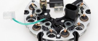
The structure of a car ignition switch
- Locking rod
- Frame
- Roller
- Contact disc
- Contact sleeve
- Block
- Protrusion of the contact part.
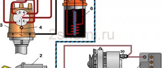
The lock mechanism is connected to many wires. They continue from the battery, connecting all the electrical devices of the car into a single chain. When you turn the ignition key, the electrical circuit is closed from the “-” terminal of the battery to the ignition coil. As a result, the current passes through the wires to the ignition switch, through its contacts it is directed to the induction coil, after which it returns back to the “+” terminal. As electricity passes through the coil, it generates high voltage, which it transmits to the spark plug. Therefore, the key closes the contacts of the ignition circuit, thereby starting the car engine.
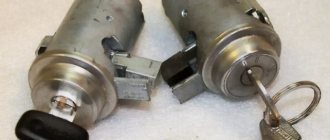
Inspection of the larva
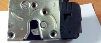
A lock without a key looks like this - stoppers stick out in all directions, which catch when turning and thus prevent the cylinder from turning inside.
When you insert the key into the cylinder, all the pins should be removed, thus they will not interfere with the key turning. In our case, we had 1 pin sticking out on the left, which clung and did not allow the “larva” to spin. We worked on it with a file.
Also carefully inspect the lock cylinder; it is quite possible that you will see burrs and even grooves on the upper side that were “trodden down” by the pressure pin running along its top. It turned out that for all the time (and the car is already 10 years old), he made his own move in the “body of the larva” (outer side), which ended in a dead end. And in this position the key was locked (position I - ignition).
There, they also used a needle file to grind off the furrow it made; make the angle as sharp as possible. It is very difficult to explain, so think about how and what should work. The lock cylinder is made of soft material and in 10 years it will definitely wear out, the rear round pin “drills” its path. Point it the right way and you won't have to buy a new ignition switch.
On sale you can find locks with cylinders (3 pieces - for the front doors and trunk) - the cost is approximately 1,300 rubles.
Or take it without the cylinders - it costs 900 rubles, but now you will have 2 keys - one to start the car, and the second to close/open the front doors and trunk. So repairing the lock is a very good option, you win in 2 categories at once - you save money, and you will still have 1 key for everything, as before.
Replacing the ignition switch on a VAZ car
To carry out repair work to replace the ignition switch of a vase, we will need: a screwdriver, a tester and a thin awl. Once you have everything you need, you can begin the repair. On all classic VAZ cars, the ignition switch is located at the bottom, on the left of the steering column. To replace you need:
- Disconnect battery
- Remove the plastic casing by first unscrewing the screws that secure it.
- Then unscrew the two screws securing the ignition switch to the bracket.
- We insert the key and set it to position 0 to disable the anti-theft device.
- Insert the awl into the hole in the bracket and press the latch. Then we take out the lock itself.
- After removal, it is recommended to mark the contact wires so that nothing is mixed up the next time you connect.
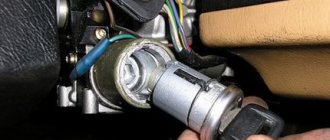
Removing the ignition switch on a VAZ-2106 begins with disassembling the steering column casing. We unscrew the five bolts and remove its halves. Before you begin disassembling the electrical part of the lock, it is very useful to disconnect the battery by removing the negative terminal or unscrewing the switch bolt. After this, remove the spring retaining ring from the back of the lock body and remove the contact group. We move it to the side so that it does not interfere, and we begin to remove the lock itself.
It is secured in the steering shaft bracket with two bolts, after unscrewing which nothing happens. It is useless to try to remove the lock from its socket if you do not know about the special stopper. It is located on the lock body under the bracket. We press this stopper into the lock with a thin screwdriver through a small hole in the bracket. Further, according to all the instructions, the lock should be pulled out freely, but this does not work.
An obstacle that is not described anywhere is the anti-theft rod. Even though it is in a “disconnected” state, it still clings to the steering shaft. To remove the lock, you have to manipulate the key. In different positions of the lock cylinder, the anti-theft device also moves and is recessed as much as possible when the key is in the “Starter” position. After a few minutes the lock can be pulled out of the bracket.
Here is the time to write that assembly of the unit should be carried out in the reverse order of removal. And in general, this will be true. First you need to insert the new lock into the bracket, recessing the latch and holding the key in the starter position, tighten the fastening bolts, then connect the wires. Particular attention must be paid to this, because an incorrectly connected contact group can damage the starter or ignition system. We reconnect the wires from the old group to the new one one at a time, checking the numbers on the contacts. After this, we assemble the steering column casing.
On the car, the ignition switch is located on the driver's side, mounted on the left side of the steering wheel on the steering gear bracket, under the instrument panel.
First of all, you need to get rid of the decorative casing of the steering shaft, unscrew the fastening screws and remove it. We performed similar actions when replacing the steering shaft.
After removing the decorative casing, unscrew the two screws securing the ignition switch to the body, then insert the key into the lock and turn on the “0” position, which turns off the anti-theft device. Through the hole in the bracket, press the lock lock with a thin awl and remove the ignition switch from the mounting socket. This completes the repair work to remove the ignition switch.
On VAZ 2108 and higher models, a package with wires is connected to the lock, that is, nothing needs to be marked and the possibility of mixing up the wires when installing a new switch is completely eliminated. Well, on VAZ 2107 and lower models, this is not the case, each wire is connected separately, so when removing each wire, it must be marked so as not to be confused during further installation.
To replace the contact group of the ignition switch, you need to use a thin screwdriver or an awl to pry the retaining ring from the edge and remove the contact part. When installing a new contact part, orient it so that terminals “15” and “30” are on the side of the locking rod.
At this point, the repair work is completed, install the new ignition switch in the reverse order of removal, connect the wires, transferring the markings from the old switch to the new one. The pinout or connection diagram of the VAZ ignition switch wires is quite simple and understandable, so every car enthusiast can carry out repairs or replace a spare part without the help of car service employees.
I installed the ignition switch from a VAZ 2110. I have not connected the microswitch yet, I only connected the backlight with the door open.
Due to the fact that the frame of the instrument panel is from a VAZ 21213, the Kalinovsky steering column casing did not fit on top. I had to cut the upper part of the casing in place and shape it with glass mat and polyester.
On the lower part of the casing at the bottom I built up the edges with plastic plates. So that less fucking would be visible.
I took it apart several times. So far I have chosen the optimal position of the steering column and ignition switch in relation to the casing and steering wheel.
We carry out the adjustment ourselves
- The first step is to install the cylinder in the correct position. Installation is carried out so that the mark on the pulley is exactly at 0 degrees.
- Set how the slider is positioned. It should be aimed at the first pin in the cylinder.
- Use a strobe light and make sure the ignition is working properly.
- Make the electrical connections in the battery: minus to ground, plus to plus.
- The sensor must be connected to the high-voltage wire on the cylinder. The mark should connect to the crankshaft pulley.
- Start the engine at low speed (up to 800 rpm). Use a stroboscope to illuminate the pulley, and if the mark coincides with the middle mark, then the ignition is set correctly.
- Otherwise, the engine should be turned off and the meter should be loosened. In order to decrease the angle, turn the sensor clockwise; to increase it, turn it counterclockwise. Record and test the calibration again with the ignition on.
- Next, you should perform manipulations with the distribution sensor. Open the lid. Match the stator and rotor mark.
- Start the engine, bring the temperature to 75-80 degrees. When the speed is 50 km/h, sharply press the gas pedal.
- If the ignition was installed correctly, a short-term detonation will occur when you press the gas.
Then there are two possible developments: early and late ignition. Let's consider solutions for both cases:
- In the case of late ignition, when there is no detonation, you should change the position of the sensor clockwise.
- In the case of early ignition, when detonation lasts longer than necessary, the sensor is rotated counterclockwise.
Niva 21213 can be subject to adjustment of the starting system by the gap at the edges of the valves, if the carburetor is removed, or by the crankshaft speed directly on the car. In the first case, the gap at the location of the lower edge (in the direction of air movement) from the throttle valve is set to a width of 1.1 mm.
It is adjusted with a screw that has a 0.7 cm hexagon on the head and a slot from the shank. This operation is carried out with the cam lever turned counterclockwise from the starting system control (all the way). In the same position, the gap at the lower edge of the air damper is set to 3 mm using a screw in the cover from the diaphragm mechanism in the starting system (you need to loosen the lock nut).
The principle of powering a carburetor engine Adjusting the Niva starting system directly in the car saves time: You need to remove the air filter from the engine, pull the control lever towards you from the air damper, and start the engine. When the air damper is forced to open (by touching a flat screwdriver to a third of its full angle of rotation) using a screw (next to the lever on the axis from the throttle valve from the first chamber), the initial rotation speed is set to 2.08.mar.0 thousand.
If you have a gas analyzer, then the carburetor adjustment in the starting system part can be done based on the amount of CO (carbon monoxide) in the exhaust gases. If, with the choke control lever fully extended, the gas rate is 8%, then everything is in order. If there is less gas than this value, then the screw on the cover of the diaphragm mechanism is tightened; if there is more, it is unscrewed and repeated measurements are taken.
It is necessary to adjust the idle speed of the Niva 2121 so that there is less carbon monoxide in the exhaust gases and so that the engine runs stably. At service stations, such work is carried out with gas analyzers on the MV. In the garage, adjustments can be made using the tachometer.
Article: 2110-3704005-30, additional articles: 21100370400530, 21100-3704005-30
Order code: 122326
I wanted something new in an old car. a decision was made to “modernize” the steering column space. I did not triple the functionality or appearance of the old VAZ “guitar”.
The lock appears to be made with high quality, everything holds tightly, the key moves smoothly. I didn’t find any fastening bolts in the kit, either they weren’t there or I lost them, the order was large, there were a lot of items. In general, I purchased separately: Bolt M6x1.0x28 VAZ-2101,2109 ignition switch x 4 pcs.
There is nothing complicated about installation and connection. You don’t even have to remove the old lock, because... 2110 is hung on the right side.
There remains 1 unconnected wire, which is a constant “+”, previously it was responsible for turning on the lighting (dimensions and headlights). It can be directly connected to the light switch, but then if you forget to turn it off, you can drain the battery. This problem is solved by installing additional relays.
To be honest, I don’t know how the circuit along the starter line was implemented on 2110, but on 2106 there were shortcomings, due to the absence of a relay in the circuit, the entire load was borne by the contact group of the ignition switch, which could lead to frequent breakdowns of the ignition switch itself. So, in order to avoid such problems with the new lock, we install an additional 12V 4-pin AVAR electromagnetic relay. According to the scheme:
This lock also has LED lighting, I haven’t connected it yet, but I will do it later.
In general, everything is fine with the ignition switch, I’m happy with the installation, it works neater than the old one, it looks prettier, the key moves softer, you can now make a switch key.
But, because If the lock is hung on the right side of the steering column, then the old casing will no longer fit.
To replace the “guitar” we will need new steering column switches, this is a matter of taste, some people install from Chevrolet Niva, others from Matiz and Nexia. I liked the Neksievsky ones better:
To install them we need:
A few on-the-spot modifications and everything falls into place:
Also, for beauty, we will need dust covers for the switches, because... The boots intended for these switches are quite expensive, but you can replace them with cheaper ones “Boot for steering column switch G-31105, Gazelle” art. 31105-3710072, much cheaper, but look no worse:
I won’t write the connection diagram here, as there are already a lot of letters