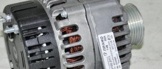
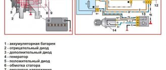
The serial models VAZ 2114 and VAZ 2115 are equipped with generators of domestic and foreign production, namely: Russian KZATE and German BOSCH.
Many car enthusiasts preferred to choose a car with a pre-installed German-type PG, since the service life of the latter is 30 - 45 thousand longer than the domestic one.
The process of repairing and do-it-yourself maintenance of a generator on a VAZ 2114, VAZ 2115 is not complicated, but it requires basic knowledge in the field of vehicle maintenance. If any difficulties arise, please consult a service station specialist.
WHAT IS A GENERATOR?
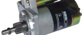
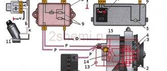
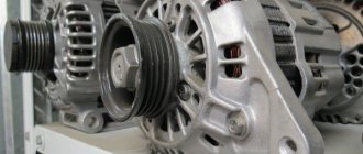
The VAZ 2114 generator can be imagined as an electric three-phase alternating current machine. It has a built-in rectifier unit that converts alternating current to direct current. The device consists of the following parts:
- Front and back cover made of aluminum alloy. Each of them has slots for installing bearings. On the back cover body there is a battery connection terminal and a connector for supplying voltage to the excitation winding. There is also a capacitor installed on the back cover, which suppresses radio interference; there is a place for installing and fastening the brush assembly;
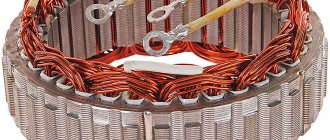
- Stator core cylinder made of transformer iron. Inside it there are grooves for laying the power windings of the generator. They have leads for connection to the rectifier block. Both covers are attached to the stator with four bolts;
- Excitation winding on the rotor shaft. It is connected with its leads to slip rings made of copper, which are installed on the same shaft. The front of the shaft has a keyway to accommodate the drive pulley;
- The brushes of the VAZ 2114 generator are a non-separable unit combined with an electronic relay controller. The relay in a metal case is riveted to the brush holder;
- A block of power and additional diodes is attached to the back cover from the inside. It contains six power and three additional diodes. To cool semiconductor devices, they are mounted on horseshoe-shaped aluminum alloy plates.
Generator set design
SOME OF ITS TECHNICAL CHARACTERISTICS
The generating set provides the following parameters:
- The excitation winding is powered by an adjustable voltage from 13.2V to 14.7V;
- The current strength of the voltage generated by the generator is 80 A;
- The belt deflection should not exceed 8 mm with a load of 10 kg.
The generator is installed on the engine on its left side in the direction of travel of the machine. The rotor rotates right, which it receives using a drive belt from the engine crankshaft.
GENERATOR FAILURES
Malfunctions of the VAZ 2114 generator can be divided into “mechanical” and “electrical”. Let's look at them in that order.
MECHANICAL FAULTS
Indirect confirmation of the presence of such a breakdown is the increased noise of the generator set while the car engine is running. It can “make noise” in some other cases, but this will be discussed a little later. The source of increased noise in most cases is worn generator bearings. This primarily concerns the bearing in the front cover of the generator. It experiences increased radial loads, so it can fail faster . Excessive tension on the drive belt increases the load on the bearing.
ELECTRICAL FAULTS
There may be several of them, these are:
- Lack of battery charging voltage;
- The generator produces low voltage;
- Exceeding charge voltage.
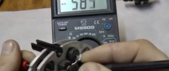
An initial check of the functionality of the generator set can be carried out without removing it from the machine. To do this, you need to have a measuring device such as a tester, multimeter or DC voltmeter. Even a simple Chinese tester will do. By measuring the voltage at the battery terminals, you can make a definite conclusion about the functionality of the generator.
The method of checking the generator, in which the positive terminal is removed from the battery, cannot be used to avoid failure of the electronic relay-regulator or other electronics of the car. We'll look at more specific verification methods a little later. Now let’s remember how to remove the VAZ 2114 generator for further inspection.
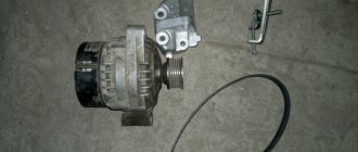
HOW TO REMOVE THE GENERATOR FROM THE CAR
It is installed in a special bracket on the cylinder block; there is also a bar for tensioning the generator belt. Find the generator in the front part of the engine compartment on the right side in the direction of travel of the car. To remove it, you need to prepare the following tools:
- Wrench set to “10”;
- The same key for "13"
- Open-end wrench 17x19;
- Head at "15"
- Mount.
We remove and do not touch the engine protection.
Removal is carried out in several ways, where it is necessary to remove the engine protection. They are well described in various sources. Let's try to remove it without removing the protection. The procedure will be as follows:
- The first step is to disconnect the terminals from the battery;
- Loosen the belt tension, remove first the belt, and then the entire tension mechanism;
- Disconnect the wires from the battery, they are covered with a rubber cover, and the connector for supplying voltage to the excitation winding;
- The generator on the bracket is mounted on a long bolt and nut. It’s not very convenient to get it, so use a “15” head to unscrew the two bolts securing the bracket to the block. They are found at the back of the generator, one bolt is long and the other is shorter. Now the generator can be turned clockwise and it will be possible to remove the axis of its attachment to the bracket;
- Unscrew the nut with a wrench to “19” and remove it together with the spacer sleeve;
Use a small punch or something similar to knock the axle out of the bracket. The generator is lifted up. Now you can use it to repair the generator or perform maintenance.
Approximate prices
In Russia, you can buy a generator for a VAZ 2114 for an amount from 1,500 to 6,000 rubles. Approximate prices depending on newness:
- New device – from 3000 to 6000 .
- Used and not repaired - about 1,500 rubles .
- Old and restored - about 2000 rubles .
Originality rates:
- The original unit - from 5000 to 6000 rubles .
- Non-original - from 4000 to 4500 rubles .
Approximate cost from different manufacturers:
- VAZ - about 6,000 rubles .
- BATE – from 4600 rubles .
- PRAMO - about 3000 .
- KZATE – 3700 rubles .
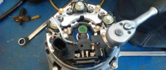
HOW TO DISASSEMBLE VAZ 2114 GENERATORS
To complete the work you will need an open-end wrench 10", 19" and a Phillips screwdriver.
Disassembly of the VAZ 2114 generator is carried out in the following order:
- Press out the three latches and remove the plastic protective casing on the body;
- The relative positions of the covers and the stator are marked to facilitate subsequent assembly;
- Using a screwdriver, unscrew the screws securing the brush assembly and remove it from the body;
- Disconnect the wires from the regulator output;
- Unscrew the four screws securing the rectifier unit, disconnect the winding terminals and remove it together with the noise suppression capacitor;
- Unscrew the four tightening screws, which were tightened with great force during assembly, and remove the cover from the side of the generator slip rings;
- The rotor shaft is clamped in a vice so that it cannot turn, and the nut securing the pulley is unscrewed. Now you can remove the generator pulley and thrust washer from the rotor shaft;
- Remove the cover from the generator rotor.
After this, you can carefully inspect all parts for wear or damage.
Replacing brushes
During regular maintenance, few people pay attention to minor generator malfunctions. Subsequently worn brushes are always a surprise. However, you should not rush to replace these parts. Initially, you need to determine why this happened, and only then disassemble the case.
The brush replacement process is as follows:
- Disconnect the wires from the generator.
- Remove the cap from the wires going to +, unscrew the nut that secures it, and remove it from the block.
- Remove the plastic casing by first releasing the clips.
- Disconnect the voltage regulator clamp and do not forget to disconnect the wire block.
- Replace the brushes and reassemble in reverse order.
Please note that you need to check the wear of the brushes by the degree of wear of the length of the rod, the value of which can be less than 0.5 millimeters. If the length of the brushes is normal, then the reason for the lack of charge is a faulty voltage regulator.
SIGNS OF GENERATOR SET PROBLEMS
- The charging indicator lamp lights up constantly or flashes while the engine is running;
The battery is not charging - Undercharging or overcharging of the battery;
- Poor headlights when the engine is running, unsatisfactory performance of wipers and other consumers of electricity;
- A strong increase in the brightness of the headlights, boiling of the electrolyte in the battery;
- Presence of extraneous noise from the generator set.
MALFUNCTIONS OF THE BRUSH UNIT
This unit may have problems with the electronic regulator and brushes. Replacing the brushes of the VAZ 2115 generator can be done without removing it from the engine. It is impossible to check this unit without removing it from the generator, so if there is such an opportunity, you can simply change the brushes. You can check its operation; there is an adjustable power supply and a control light. Connect the power to the “+” and “-” of the regulator, and the light bulb to the brush. It should glow, and when the input voltage increases to 15-16 volts, the light goes out. If this does not happen, then the tablet needs to be replaced. Let's look at the signs of brush wear. This will be indicated by:
- Low on-board voltage;
- Lack of battery charging;
- Charging voltage surges.
Brushes in a free state must have a length of at least 0.5 cm. If the length is shorter, they must be completely replaced. Check the condition of the brushes and their free movement in the grooves. If there is a hang, it can be eliminated by dropping a drop of oil into the grooves. Check the slip rings and their surface for wear. If present, you need to sand the surface of the rings with fine sandpaper. When the brushes of the VAZ 2114 generator are replaced, performance will be restored in a few minutes, after grinding in the brushes and slip rings.
Brush unit
DIODE BRIDGE AND ITS PROBLEMS
Signs of a faulty generator diode bridge may be as follows:
- Complete lack of charging;
- The charging voltage is significantly higher than normal.
All this can cause great negative consequences for the entire electrical system of the car. Repairing a generator with your own hands is possible, but only if you have experience and equipment for working with electrical equipment. For example, signs of a broken diode bridge have been identified and require repair.
Most often, in this case, a breakdown of the “horseshoe” power diodes occurs. Replacing them is not very difficult, the problem is that they are not available in spare parts. You can look for repairmen who repair electrical equipment of cars. It will be easier and cheaper to purchase a new unit with a diode bridge and install it to replace the failed one. The diode bridge is replaced in the following order:
- Mount a contact bolt with insulating bushings and nuts in the block and tighten it;
- Correct and reinstall the leads of the stator windings and screw in the nuts at their connection points;
- Replace the bolts securing the rectifier unit and tighten them;
- I install the brush assembly with the regulator in its place, and secure it with screws on the back cover body;
- Install a protective plastic casing and secure it with three clips.
After this, the device can be mounted at the installation site, the wires can be connected, the drive belt can be put on and tensioned, and its operation can be checked.
Diode bridge (rectifier)
Combating voltage sags VAZ 2113, 2114, 2115
I decided to replace the positive wire from the generator to the battery, the negative wire from the battery to the engine and to the body, and throw ground from the generator housing to the body. During the work, I also replaced the positive wire from the starter to the battery.
Before this large-scale exercise, I purchased three meters of wire in a thick rubber sheath, with a cross-section of 25 square meters. Although three meters was not enough for me, I should have taken three and a half. Fortunately, I found a piece of such cable in the garage. A meter of cable cost me 115 rubles, a total of 345 rubles. three meters away.
I also bought six new thick lugs for the wires. The tips I chose were copper and tinned, with 6mm holes. I figured that I would need 8 mm holes, but I didn’t know how many in advance and decided to take those and during the work which ones would need to be drilled out to 8 mm. The price of one tip is 20 rubles. All six cost 120 rubles.
I also bought six copper sleeves, just in case, but they were almost of no use to me, just one. But it’s okay, they’ll be useful on the farm. The price for one sleeve is 15 rubles, for six in total - 90 rubles.
At one time I decided to replace both terminals on the battery. The old ones haven’t inspired confidence in me lately, they’ve let me down a couple of times already, and they also tighten with a hexagon, and I’m already tired of it.
Old terminals. They're not bad, but I haven't really liked them lately.
Wires, terminals, lugs, sleeves (almost of no use).
I chose the thickest ones that were coated, had a large main input for power wires and additional inputs for additional ones. equipment, and it’s imperative that the tightening be done with an ordinary open-end or socket wrench, it’s more convenient for me.
To begin with, I rummaged around the grid, in the hope that someone would tell me which of the three generator wires goes to the battery. Of course, I guessed that the one that comes alone, and not the one that is doubled on one of the two terminals, is what I was looking for, but, still, being on the safe side is a serious matter. I never found anything. Basically, many people leave the old wire and pair it with a new one. This option did not suit me at all. In general, I found the wire I needed on my own, it was already clear from it that it was necessary to leave it, it was already burnt and dried out. Pulled it out from under the hood
Here it is, the one that goes from the genes to the battery directly.
I cut a new wire to its length
Old and new wires. Comparison.
I stripped the end and tinned it using a soldering iron I have in my garage with a power of 300W, it coped with this task easily. So that the wire inside does not oxidize later.
After which, I put the tip on it
Then I tightly crimped the tip in a vice and heated it together with the inserted wire with a soldering iron so that they would merge into one. I insulated it with a thermal tube in the color of the positive wire, for convenience and according to Feng Shui.) At the same time, I drilled a hole in the tip with a diameter of 8 mm, since the bolt on the generator (I have a Priorovsky 115A) has a thickness of 8 mm.
Using the same scheme, I then attached all the lugs to all the wires. At one time I replaced the tip on the second and third double wires, as it turned out that the tip was a little weak, I didn’t like it
The second and third wire genes are doubled on one tip. I'm fine now.
While I was working on this wire, I paid attention to the starter power wire, it was still normal, but already pretty stiff. I decided that since there was such a booze, I would replace him. This is the wire I didn’t count on, I found the same wire in the garage, a piece, and made a new one for the starter. This is where one sleeve came in handy, since six pieces were also not taken into account for the starter. I made a tip out of a sleeve, tinned it and that was it. Then I secured both wires (starter and generator) in the positive terminal and put a corrugation on them, for reliability, after all, a lot of current flows through them.
This is how the finished power wire for the generator and starter turned out.
Using the same scheme, I replaced the ground wire from the engine and body
Engine and body ground wires
Ready negative wire for the engine and body.
In principle, the bulk wire could not be corrugated, but I had corrugation, so why not put it on, it looks better and it won’t be unnecessary. It's time to put all these things in place. I screwed the positive wire to the generator
Then the ground wire to the engine and to the body
The mass is ready for the engine.
It's time to deal with the ground wire from the generator housing to the body. Everything was immediately clear about the place of fastening to the generator, but I didn’t immediately decide on the place of fastening to the body. I didn’t like the option of fastening it with a self-tapping screw near the washer barrel. It’s somehow dead and not reliable. Moreover, it will be difficult to check the tension of the alternator belt. In short, I didn’t like this option. I decided to screw it to the headlight mounting bolt. It’s more convenient and looks more aesthetically pleasing. I almost forgot to say that I placed serrated washers under all the tips so that their contact with the body and engine would be optimal. Also here, I put a toothed washer on the headlight bolt, and only then tightened the wire end. Although the headlight bolt has little to do with the weight of the body, the wire is well fed to ground through the toothed washer and reliably.
Generator ground wire to body. One terminal with a 6mm hole for the headlight bolt, the other with an 8mm hole for the generator bolt.
I think you can see in the photo how the ground wire of the gene is located, where it was screwed.
When I finished everything, finished with the injector, assembled everything, screwed the terminals into place to the battery, lubricated them with a little grease at the point of contact with the battery.
Started the engine. By the way, before this operation, charging on a cold engine, according to the tidy, floated from 13.8 to 14.2, and on a warm engine, recently, according to the tidy, it dropped to 13.3, 12.9. Because of this, the battery began to charge poorly and once I even had to charge it, after which I forgot to tighten its caps and lost one. Now he looks like a wounded man with a plug. The result of the work, with a cold, running engine, but not with consumers turned on, according to the tidy readings, charging became stable at 14.6.
Charging on a cold engine. Stable 14.6
After the engine has completely warmed up, the charge drops to 14.3-14.4
The charge on a fully warmed up engine does not fall below 14.3
Then I turn on the backlight (by the way, my backlight is not stock and takes a much larger load, the loss on the backlight is 0.4 volts), fogs, lights, heater in the first position (the most popular one for me, it’s enough for me, it cooks well) Charging is at least 13.8 according to the tidy readings.
Charging on a warm engine with the lights on, headlights, PTF and the heater in the first running position 13.8
This is the most current mode of my car now - the heater in the first position, light, fogs and backlight. For optimal charging of the battery, charging directly to the battery should be at least 13.6, I think it’s 14.52 and it won’t boil.)) and that’s quite enough. In short, I'm happy.
Total: 1. Wire 25 square meters, 3 meters for 115 rubles. — 345 rub. 2. Tips 6 pieces for 20 rubles. — 120 rub. 3. 6 pieces of sleeves (only one was useful) for 15 rubles - 90 rubles. 4. Battery terminals pair - 530 RUR. 5. Soldering iron, tin, heat pipes and other tools are always available. 6. The desire to change something for the better, a clear head and calmness, only calmness.))
If I had the stock backlight, then I think the charging would be even higher, since the backlight takes a decent amount from me. In the future, there are plans to replace the double wire of the generator, I think it won’t hurt. To everyone who did not understand from the measurements, the readings were taken from the dashboard and not directly from the battery. And this is a big difference. The tidy shows residual voltage with all losses. And not the first current output from the generator. Measurements from the battery with consumers not turned on show 14.62-14.65 on a cold engine and 14.52 in general with all consumers turned on at full power. Is this not enough? I haven’t taken measurements yet on a warm engine, I don’t have time.
So far I have made measurements only on a completely unheated engine, since there is no time for this yet. I couldn’t do it earlier because the multimeter treacherously died at the wrong moment. The first measurement is a running engine without consumers turned on
The first one froze. The engine is cold. Consumers are not included.
The second measurement is WITH ALL consumers IN GENERAL - Lighting in the cabin and outside, High beam, Front PTF, Rear PTF, Heated rear window, Heated mirrors, Heater in the third maximum position, Music (without subwoofer).
The second froze. The engine is cold. All consumers are included.
I decided to replace the double alternator wire, but have not yet made a final decision on what to do with it. First, I found it in the block near the mounting block
Here he is, darling. Or rather, they are two thick, pink ones.
The question arose that if, instead of two double ones, you insert one or more wires of a larger cross-section, then a problem may arise with how to fit them into the block. Of course, you can do it without it, but I don’t like this option. And one moment. Since the wires will be much thicker, I am afraid that there will be no loss on such small terminals. I found some free space in the block and have thoughts of using it. Perhaps I’ll consider this option - I’ll run three wires of a larger cross-section than the original ones, but not very large, and spread them across three mothers, in total I’ll get one with a larger cross-section.
The size of mothers somehow does not inspire heroism.
I decided to remove the block and see what's what. I took it off the car and took it apart. The condition, in principle, is okay, but from the appearance of the board it immediately became clear that water gets into the block from time to time, and this is not ice. The board has oxidized in some solder areas and the varnish has begun to peel off from some of the tracks.
An autopsy showed that water was getting into the block.
The white wire in the photo, I once duplicated one of the tracks, because the varnish had peeled off, it had oxidized and there was a suspicion that it had a short circuit. I cut it off and replaced it with wire.
The second side of the board. Well, it's more decent here.
I found out where both wires come from the generator. It turned out that they come to a common plate with male terminals and, by the way, the empty contact of the block also comes to this plate, this is already good...
Here is the same contact plate. Both wires from the generator come to it and there is one more free contact.
The only thing that confused me was that this plate was attached to the board with what seemed to me to be thin legs. No matter how there are losses lurking here... In the top photo you can see only the central tendril of the plate that it is thin, but in the lower photo you can see that all three tendrils are the same - thin.
All three antennae are thin and connected on one bridge.
It also became clear that all three antennae were soldered to one common jumper. I also didn’t really like the cross-section of the jumper. Because in fact it is a continuation of the input double wires from the genes and does not even correspond to their cross-section. Immediately such a specific brake is right at the beginning of all consumers. I think that I will try to increase it. I also discovered that on one of the plastic halves of the mounting block there are some male terminals with jumpers between them. I didn’t like their jumpers either; they were rather weak in my opinion. Maybe not everything, but I would strengthen everything.
Jumper terminals. In my opinion, it wouldn't hurt to strengthen it.
In general, having dealt with all these matters, having found out partly what was what, I first decided to wash the board and covers. Since I don’t have a special means for cleaning boards, I washed it with regular warm water using an old toothbrush. Then I dried it thoroughly on the radiator. Almost all of it was washed off, although in some places there was still some oxide left; I think it formed during drying. Well, I don’t bother with it yet, then I’ll deal with it, but for now I’ll take up the soldering iron. First of all, I decided to start with what seemed to me the easiest and fastest thing - with the jumpers on the block cover. Two options arose in my head: either replace them completely with thicker ones, or duplicate them with a wire of a slightly larger cross-section and thereby reduce their resistance. I decided to take the second route. I found in the garage a copper wire varnished with a protective varnish of a slightly larger cross-section than the jumpers, and with the help of wire cutters and pliers I began to give it the shape of the jumpers. Let me tell you, this activity is boring.
I made several jumpers, then soldered them parallel to the original ones.
They look similar, only gold.
I studied with them from seven in the evening until three in the morning. The result is below
Later I decided to cover the soldering areas with a special varnish so that they would not oxidize if water suddenly gets in. But that will happen later, when I finish all the work on the block. Next I decided to replace the jumpers on the board. Notice how dead they are. Perhaps there are enough of them, of course, in principle, but I didn’t like them at all. On my board they are made of wires with blue and black insulation, you can see it clearly in the photo
I decided to replace the stock jumpers
In the garage I found a single-core copper wire, 2.5 square meters. In the photo below you can see how much thicker it is than the standard jumper, and in general you can see how thin it is, it’s just crap.
On the left is a replacement. On the right is the one that was on the board.
After I prepared a new jumper, I was faced with the fact that the old holes in the board for the jumper do not fit the new one, they are too small. Having thought about it and carefully examined the battle site, I determined that the holes can be safely drilled and this will not create interference such as shorting the tracks during soldering. For this task, I needed a 2.2 mm drill. I inserted it into the screwdriver and carefully drilled the holes.
Using a screwdriver and a 2.2 mm drill, I drilled out the standard holes.
Then, I soldered the first jumper, everything worked out with a bang.
First substitution, result. The difference from relatives is noticeable to the naked eye.
Thus, almost all jumpers were replaced
Result. Almost all jumpers have been replaced.
I soldered all new jumpers to replace the original ones. The operation to replace them was quite successful, although the process itself took quite some time. I decided to strengthen the main power jumper, the one that connects the input connector of the terminals from the generator to the block, since it seemed to me too thin in relation to the cross-section of the input wire. Why I took a piece of copper wire with a cross-section of about 6 squares, bent it into exactly the same jumper as the original one, and tinned it thoroughly
Additional jumper to the original one.
And soldered it on top of the old one. I didn’t solder it along its entire length, since I don’t think it’s necessary, I soldered it well in the places where it connects to the terminal connectors. So that the passage to them is not hampered by narrowing in some places along its perimeter.
I soldered a new jumper. She fell into place together with her family, just as she was there.
I decided to solder all the legs of the terminals that connect to this power jumper, since the terminals themselves, in principle, are more or less made wide, but their attachment to the jumper is very narrowed and is in the form of thin legs. I reinforced these same legs in diameter by soldering tin so that they were no smaller in diameter than the terminals themselves. My camera can’t handle it from such a close approach, so I took a photo as best I could. In the second part there is a photo of the terminal legs attached to jumpers, and here are their photos already reinforced by soldering
Soldered and enlarged legs of the input connector.
On the input connector of the terminals there are three of these same legs. Two pass through the board completely in their entire width and then sharply narrow, and the middle one narrows on the other side of the board and then the initially narrow one enters. I thought about what to do with it, but then gave up and decided to leave it as it is, and direct the entire load to the remaining two, and strengthened them as much as I could. When I finished with this, the idea was to solder all the tracks of the board in order to strengthen them and increase their volume for better conductivity. But the only thing here is that this work, or rather the work on the side where the fuse terminals, relays are located and all the jumpers are soldered in, had to be done before the new jumpers were soldered in. Otherwise, they interfere and in order to do this, they need to be desoldered again and all that. And I spent so much time on this. In short, I messed up a little with this matter. I decided, okay, I’ll try to do without this procedure for now. For prevention, I strengthened the first track, the one that goes from the input and to the first terminals of almost all fuses
I reinforced the path from the connector to the fuse terminals.
At this point, work with the block had to be suspended, since a machine was needed and the block had to be put in place. Of course, I couldn’t help but pay attention to the tidy readings…. Of course, I was specifically worried that all the work had gone down the drain and the time spent on it was wasted. I started the car. The tidy readings, as before, remained no lower than they were before - 14.6
The instrument readings on a cold engine have not changed since the first modifications. At least 14.6 left
Well, everything is clear here. After the engine was completely warmed up, the tidy readings dropped to 14.4. And this was already at least a little, but more than before I re-soldered the block. Before this, the tidy readings (after replacing the gene-battery + mass wires) were 14.3-14.4, it was more stable at 14.3.
The instrument reading after the engine has fully warmed up is 14.4. Before working on the block they were slightly less than 14.3
With a trembling hand and numb fingers, I began to turn on the consumers. I turned on all my lights (far from stock, it sags very badly), high beams, front PTFs, rear PTFs, heated rear window, heated mirrors, heater (heater) at full power in the third position, music (without subwoofer). The tidy showed me 14.0.
The instrument readings are fully with all consumers at full power, with a warm engine, 14.0
I tried to turn off the heated rear window, since it takes a very large load, even more, it seems to me, than the stove, the tidy readings rose to 14.1.
Tidy readings on a warm engine, with all consumers turned on, but with the rear window heating turned off, 14.1
Well, I very rarely drive with the heated rear window, mostly after wet snow, when leaving the parking lot. So I don’t take its load into account; basically it is not turned on. The work did not go down the drain. I skated for a day, no problems were identified with the operation of the unit, and the tidy began to please me with different numbers. I decided to finish the work on the block for now, since the result obtained is now quite enough for me. I took it off the car again, took it apart and coated it thoroughly with varnish twice so that any moisture that got into the block would not interfere with my work.
I varnished the lid jumpers.
I even coated as much as possible all the terminals of the connectors and fuses, at least on the outside, so that they too would not oxidize, well, at least to reduce oxidation to a minimum.
I filled the board with varnish from the heart.
I spilled the board conscientiously, twice. And I varnished the outer sides of all the terminals as much as possible.
I dried the board thoroughly on the battery. Then I started assembling the block. To prevent moisture from getting into the block, I decided to coat the joint of the halves of its body with silicone sealant. I think that if it is necessary to disassemble the block, it will not become a big obstacle when it dries out, and at the same time it will not let water into the block.
I coated the joint between the block halves with regular black silicone sealant.
I decided to coat the location of the terminals of the upper connector of the block with sealant, since most likely they were where most of the water got into the block. I smeared sealant on the bottom of the terminals, in the skirts of their glue, with which they were fixed from the factory in the top cover before disassembling the unit
I applied sealant to the bottom of the terminals of the upper connector. This is where most of the water gets into the block.
And assembled the block into a single whole.
Assembled the block. Then I coated the seam with sealant again to be safe.
I put it on the battery assembled until the next day so that it could dry thoroughly in the warmth. And while the block was drying, I decided to start replacing the wire from the generator to the mounting block. Having previously purchased 5.5 meters of PV-3 wire with a cross-section of 6 squares and a tinned terminal for it, the same as I installed on the wires in the first part, with a diameter of 25 squares. The price for one meter of wire is 31 rubles, the price of a terminal is 20 rubles. And also, I was lucky, I found automotive corrugation, and even just the diameter I needed and not in pieces of one meter each, but in pieces of whatever meter I needed. The price of one meter of corrugation was 32 rubles per meter. Why did I need 5.5 meters of wire? The issue there is that a wire with a larger cross-section cannot be pushed into the connector of the unit into which the wires from the generator enter. The original wire has a cross-section of approximately 4 squares, and it is doubled, that is, its total cross-section is approximately 8 squares. I decided to increase the cross-section of the wire and add another, third wire to the existing empty connector slot. And even three wires with a cross-section of 6 squares each gave a total of 18 squares of total cross-section. I folded the wire in three and cut it into three identical pieces, the length of each was approximately 1.8 m, this was quite enough for the entire length from the gerator to the mounting block, even with a little extra margin. Stripped the ends of all three wires
I stripped the ends of all three wires and combined them into one cable.
covered them with tin, put on the tip, warmed it up thoroughly, then quickly clamped it in a vice and pulled it out heartily. Then I insulated the whole thing with red heat-shrink tubing. For convenience and according to Feng Shui, it’s a “plus” after all.
Warmed it up, pressed it and covered it with a red heat-shrink tube.
I pulled all three wires together with thermotube rings after some distance so that they were in one bundle
Almost ready new cable from the generator to the unit.
Then I stripped the other ends of the wires and soldered the “mother” terminals to them. I also insulated them with a red thermal tube so that everything was a bunch. in all senses.
I put a corrugation on the resulting cable. I crimped it along its entire length at an equal distance with rings from a thermal tube, and closed it at the ends with a red tube.
Ready cable from the generator to the unit.
I did not remove the old wires from the generator to the block. I looked, there was too much work there to pull them out of the common harness and from the corrugation. I decided to simply turn them off and cut off the ends so that they wouldn’t dangle and confuse me. I stretched the new cable along the location of the old one, securing it along its length with plastic clamps. The next day the block had dried well and I put it in place. As a preventative measure, I sealed the bottom of the extreme edge of the block with sealant so that after installing the block underneath it, no water would get into the interior. I connected a new cable and that's it, basically. By the way, I replaced the corrugation on the previously made battery ground and positive wires. Photos of wires with new corrugation are in the first part of this topic, if anyone is interested, take a look. I started the car. And, to be honest, the readings on my dashboard haven’t changed at all. The only thing is that when such powerful consumers as the heated rear window and the heater were turned on, the short-term voltage surge decreased noticeably, I felt it immediately. But the residual voltage according to the tidy readings was not affected by replacing the wire. Well, at least to reduce the surge, the work was not done in vain.
In general, the greatest increase in voltage and decrease in losses for me occurred after replacing the wire from the generator to the battery, replacing all the power ground wires, and installing additional. ground wires of the generator and soldering of the mounting block. Replacing the wire from the generator to the block did not give a noticeable increase in my car.
If someone wants to strengthen the board tracks, then I think that this will also make changes to the instrument readings. I haven’t gotten around to it yet, but I’m very happy with the results I got.
But the readings taken from the battery on a fully warmed-up engine, with absolutely all consumers turned on at full power, I don’t know about others, but for me this is enough to fully charge the battery and prevent it from boiling.
Indications. Fully warmed up engine. All consumers are switched on at full power. 14.3
Result: 1. PV-3 wire with a cross-section of 6 squares, length 5.5 m. — 171 rub. (price per meter - 31 rub.) 2. Tinned terminal, for a wire of 25 squares - 20 rub. 3. “Female” terminals, three pieces, were in stock. 4. Heat shrink tube of different sizes and colors - was in stock. 5. Plastic harnesses, a soldering iron with solder, and other tools are always at hand. 6. Automotive corrugation, diameter 15.7 mm, length 5.5 m (for all wires that were previously replaced and this cable) - 176 rubles. (price per meter - 32 rubles)
https://www.drive2.ru/l/2520980/, https://www.drive2.ru/l/2556082/, https://www.drive2.ru/l/2582257/