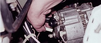
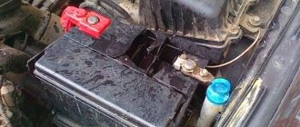
The VAZ 2107 generator is checked without removing it from the car. To do this, you will need a voltmeter or multimeter and a test lamp. Checking the VAZ 2107 generator consists of measuring the voltage it produces under load and without turning on consumers. If you suspect a generator malfunction, you must first check the tension of the generator drive belt. If the belt tension is normal, then check the voltage at the battery terminals. The voltage value at medium crankshaft speeds and high beam headlights on should be in the range of 14.5 - 13.5V.
Overcharging is characterized by increased voltage at the battery terminals, that is, a voltage above 14.5 V. The reason is related to the voltage regulator. Most often it is faulty, but poor contact in its connections is possible. The cost of the regulator is usually not high and in this case it is easier to replace it. Before replacing, clean the contact area between the negative terminal of the regulator and the generator housing.
Checking the generator with a multimeter
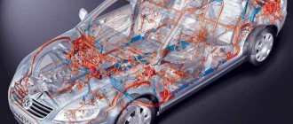
The electrical equipment of a modern car is a complex set of instruments and devices. The on-board power supply is supplied from the battery, and after starting the engine - from the generator. This device, in good condition, provides a voltage within 14 - 14.2 V. Checking the VAZ 2107 generator will not only help identify its malfunctions, but also avoid battery failure.
If the voltage is insufficient, its charge becomes incomplete, which causes a drop in the density of the electrolyte. At low temperatures, this phenomenon can cause the liquid to freeze. The formation of ice crystals leads to the gradual destruction of the battery plates. To establish the output voltage parameters of the generator, you can ring it with a conventional multimeter.
The main function of the diode bridge on the VAZ 2107
The diode bridge of the VAZ 2107 generator is its integral and integral part, which serves to transform alternating current into direct current. The current is converted due to the fact that the vehicle's on-board network has a constant voltage of 12 V. An alternating current is supplied to the bridge, which is converted, and then goes to the battery in rectified form. And the voltage is removed from the battery and used to power all electrical appliances on the car.
This is interesting! Many people are accustomed to thinking that the on-board network of a car has a voltage of 12V. However, 12V is the battery voltage at rest, and in order to charge it, a charge of 13.5 to 14.5 volts must be generated. To ensure normal voltage supplied from the battery, the diode bridge is assembled from 2D219B diodes.
Signs and reasons why a diode bridge breaks
Malfunctions of the rectifier unit on the seven and other cars lead to complete immobilization of the car. If at least one diode located inside the generator fails, the supply of charging current to the battery will stop. The car will not drive for a long time without charging the battery (maximum 1.5-2 hours, provided that the car has a new and working battery and all electricity consumers are turned off) . Like all parts on a car, diodes tend to deteriorate (burn out), so if a decrease in the voltage of the on-board network is detected, which usually drops below 12V, and then begins to gradually fall, then the device should be checked and repaired.
The causes of breakdowns of the generator rectifier unit are as follows:
- Moisture getting into the generator. This can be either condensation or water that comes from outside during the operation of the car in rainy weather.
- Development of diode life. Usually in this case one diode fails, while all the others remain intact. The average service life of diodes is about 10 years, but it also depends on the mileage of the car.
- Burnout due to motorist negligence. Most often, diodes burn out when the car is not properly lit. If you light it incorrectly, then in this case you may have to change not only the diode bridge, but also the entire generator.
The first symptoms of rectifier unit breakdowns are identified by the following signs:
- The voltage of the on-board network decreases while the engine is running. This can be detected by the presence of an electronic voltmeter, which can be installed independently by the owner of the VAZ 2107. If the car has an on-board computer, it will also notify the driver of the malfunction. If there is no voltmeter or on-board computer, then a decrease in voltage can be diagnosed by such a sign as a decrease in the brightness of the lighting fixtures.
- The car loses power, and the longer you continue to drive with a faulty generator, the more the battery will discharge.
To establish the exact cause of such symptoms on the VAZ 2107, it is necessary to test first the charging current of the generator, and then the diodes. Sometimes the cause of a decrease in voltage may be oxidation of the terminals and contacts on the generator, and after cleaning them, the problem will be solved.
Checking the diode bridge
You can find out why the on-board network voltage is decreasing by checking the generator to ensure its serviceability. Burnout of the generator winding occurs rarely, but such a breakdown cannot be ruled out. The diode bridge can be checked by the vehicle owner independently without the need to visit a service station. If the check shows that the element is working, it means that the generator itself needs repair, but looking ahead, it must be said that sometimes it is easier to buy a new element than to change the winding on the old one.
Checking the voltage regulator relay
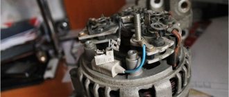
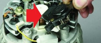
If everything is in order with the stator winding, then we move on to checking the voltage regulator, which is usually attached to the generator itself and is usually a dark box with terminals and often looks like this:
When you remove it, you will see the black carbon brushes of the generator; you also need to visually inspect them to see if they are purposeful and press them inward with your hand. Serviceable brushes should move freely along the channels and should protrude outward by about 5 mm; if their protrusion is much less than 5 mm, then they are worn down and the voltage regulator needs to be changed.
There are two ways to test the voltage regulator.
1) Check without removing the generator from the car (an assistant is needed) 2) And by removing the generator and disconnecting the regulator from it
The first way to check, with an assistant
You can check the generator without removing it from the car. To do this you need to start the car. Then we take a multimeter and turn it on to measure the voltage (select a measurement limit of 20 Volts or more). We measure the voltage at the battery terminals with the device; at idle it should be within 14 Volts, plus or minus 0.3 Volts. Now we ask the assistant to press the gas pedal. And again we look at the multimeter readings. The voltage on the device screen should not change by more than 0.5-0.6 Volts. If the difference is much greater, then the regulator is faulty and needs to be replaced.
Second way to check (with the generator removed)
To do this we need two additional voltage sources. One with a voltage of 12-13.5 Volts, and the second with a voltage of 16-20 Volts. For the first of them, a car battery is suitable, and the second source can be obtained using the same battery if you connect a couple of ordinary AA batteries in series with it.
Something like this picture:
Be careful when doing this check! Or use fuses in the circuit to prevent short circuits and fire. . 1) Connect the plus of the battery to the regulator terminal, and the minus of the battery to the regulator body
And we connect a 12 volt car light bulb to the brushes. If the regulator is working, then we will see that the light will light up
1) Connect the plus of the battery to the regulator terminal, and the minus of the battery to the regulator body. And we connect a 12 volt car light bulb to the brushes. If the regulator is working, then we will see that the light comes on.
2) The second stage of testing: we take the same battery, connect a pair of batteries in series to it, observing the polarity, so that the output voltage is from 16 to 22 Volts. And we do the same thing as in point 1. This time, the light bulb connected to the brushes should not light up. If it does not light up, then the regulator is working. And if the light comes on again, then the generator needs to be replaced with a new one.
If you have any questions, this video will help you understand how to do this check correctly:
We checked the stator coil and the relay regulator, now we also need to check the diode bridge.
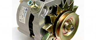
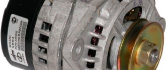
What generators can be installed on the “seven”
The design of the VAZ 2107 allows the installation of not only the G-221A generator. Therefore, if necessary, the driver can install a more efficient device, but in this case some changes will have to be made to the electrical circuit of the car. The question arises: why should a motorcyclist even change his “original” generator?
The G-221A was the optimal device for equipping cars at the beginning of mass production. However, a lot of time has passed since the 1980s, and today almost every motorist uses modern electronic devices:
- sound systems;
- navigation systems;
- additional lighting devices (tuning), etc.
Accordingly, the G-221A generator cannot cope with heavy loads, so drivers begin to look for more powerful units.
At least three more powerful units can be installed on the “seven”:
- G-222 (generator from Lada Niva);
- G-2108 (generator “eight”);
- G-2107-3701010 (Car injection model with carburetor).
It is important that the last two models do not require changes in the design of either the generator housing or its mountings. If you are installing a Niva generator, you will have to make some changes.
Video: principle of operation of the generator
Connection diagram G-221A
As an electronic device, the generator must be used correctly. Accordingly, its connection diagram should not cause misunderstandings. It is worth noting that the “seven” drivers can easily connect all the generator terminals on their own, because the circuit is accessible and understandable to everyone.
Many car owners wonder where to connect which wire when replacing the generator. The fact is that the device has several connectors and wires, and when replacing it is easy to forget which wire goes where:
- The orange one is useless for wiring, you can leave it as is or connect it directly to the gray one to start automatically;
- a thick gray wire goes to the brushes from the voltage regulator;
- the gray thin wire goes to the relay;
- yellow wire - coordinate indicator lamp on the control panel.
Types of relay-regulator
To exaggerate, there are only two types, but each works on the same principle, namely, “cuts” or increases the voltage to the desired level.
Combined with brush assembly. Usually it is mounted on the generator itself, in the housing where the brushes are located, there is also a relay regulator.
Separate. Usually it is mounted on the car body, the wires go from the generator to it, and only then to the battery.
The housings are non-separable and tight and of a different type (often filled with sealants or special adhesives), that is, they cannot be repaired. To be honest, they are quite cheap, especially for our VAZs, so it’s easier to buy a new one than to tinker with an old one.
These are the most common types, of course, previously there were so-called ones combined with terminals, but they didn’t catch on because the device is not very convenient, so I won’t talk about them.
If your relay is “broken” and is constantly recharging, then it’s worth changing it, but first you need to make sure that this is the problem. Now there are only two ways to check: - without removing it on the car itself, and checking an already removed relay. Let's look at both options.
On the generator
In the second picture you can see how the diode is installed, but with such a length of wiring it is not very convenient - everything is tight. It is better to make the length of the wire about 2 cm from the diode - this way, in my opinion, it will be easier to insert into the RN connector of the generator. As far as I remember, I have a K223 diode, i.e. it's silicon. Raises the voltage by about 1.3 V.
I’ll correct myself - I checked using reference data on the Internet what the K223 diode is - I must say that I was very mistaken in indicating exactly that name. In fact, there are diodes KD223 and D223, but their housings are completely different.
However, in the photos I provided, most likely diodes D214 or D242 are wrapped in electrical tape (there may be different letters after the numbers), here is the case (M6 thread):
Common breakdowns
Generator faults can be electrical or mechanical. These include:
- loss of functionality of the voltage regulator;
- breakdown of the rectifier unit (diode bridge);
- short circuit of stator windings;
- current short circuit in the rotor winding;
- wear of bearings and brushes.
Read also: B20100g datasheet in Russian
Voltage regulator
The purpose of this unit is to normalize the voltage before feeding it into the automotive electrical circuit. You can check the serviceability of the regulator by checking the voltage that it supplies to the battery terminals. This indicator depends on the model and brand of the vehicle and varies between 13.5-15.5 V. Therefore, you should find out in advance what voltage your particular type of regulator produces. This can be done by studying the manual for using the machine. For example, you can take a VAZ 2107 or 2110 car, since these vehicles have the most typical faults associated with the integral and relays.
Using a Multimeter
To check the VAZ 2110 generator with a multimeter, you need to switch the device to voltmeter mode. Then you need to connect its probes to the battery terminals. The most important thing is to observe the polarity and turn off the car engine. The voltage normally varies from 12 to 12.8 V. Next, the procedure should be repeated, but with the engine running. The voltage readings should rise to 13.5-15.5 V. Lower and higher voltage values indicate a malfunction of the generator.
Checking the generator without removing it from the car
A bridge of diodes performs the functions of a kind of alternating current converter. It contains three negative and three positive diodes.
Before checking the bridge, you need to disconnect all the wires coming from it and from the voltage regulator. You also need to remove the ground anchor from the battery in advance. First you need to check the rectifier for short circuits. We activate the ohmmeter mode on the multimeter and connect the red (positive) probe to the positive contact of the diode bridge, and the negative probe to the surface of the housing of the generator itself. If the rectifier is fully operational, then the readings of the measuring device will go to infinity. In other cases, the rectifier will be inoperative.
Testing of stator and rotor windings
A common breakdown of a car generator is a short circuit in the windings. It occurs when current surges are too intense, brushes wear out and liquid gets in.
So, you need to remove the rotor and find a pair of slip rings on its structure that will need to be ringed. Having started the ohmmeter mode on the multimeter, we connect the probes to these rings. Normal resistance is 2-6 ohms. If you get large values, then there is a loss of contact between the slip rings. If the device shows lower values, then an interturn short circuit has occurred.
Then you should measure the resistance between zero and the terminals of the windings. The normal value is no less than 0.3 Ohm.
Wear of brushes and bearings
If you have already disassembled the generator, then it is advisable to check the condition of the brushes. They can wear out or break due to misalignment of the rotor shaft. If the brushes are damaged, they should be replaced with new ones.
Inside a car alternator there is a pair of bearings. One is fixed on the rotor shaft, the other is in the center of the cover. The whistling and hum of the generator when the engine is running is a clear sign of bearing wear. In this case, the generator housing can become very hot. If you notice such signs, it is better to replace the bearings immediately, otherwise you may encounter more serious problems.
You can check the bearing by removing the belt from the generator and trying to rotate its shaft with your own hand. If the part rotates freely and easily, then everything is in order. If it is difficult to rotate the rotor, then you should not delay replacing the bearings.
How to check the generator for performance? Self-check and repair of the generator
A generator is a typical electrical station that provides energy to all engine systems: power, cooling, ignition, so its failure will inevitably lead to other malfunctions. To prevent breakdowns, you need to systematically diagnose it, and if problems cannot be avoided, repair it immediately.
In this article we will talk about how to check the generator for performance without resorting to the help of professionals. But before that, let's look at the symptoms of its possible defects.
Read also: How to make a snowmobile from a trimmer with your own hands
Diagnostics without dismantling
To troubleshoot, you will need a multimeter and a test light. By measuring voltages, you can determine a potential breakdown that needs to be eliminated.
Initially, determine the voltage value while the engine is running at medium speeds with the load on (high beam, for example). Indicators in the range of 14.5-13.5 V indicate that everything is normal. Otherwise, repeat the test with electrical appliances turned off. Additionally, find out what voltage is supplied between pin 30 and the generator housing.
If, during the diagnostic process, the voltage at the battery terminals with the load on is below 13.5 V, and with the consumers turned off, the indicators slowly rise to 13-13.4. Then the problem most likely lies in poor contact from pin 30 to the battery and poor contact of the negative terminal to the motor housing.
To check the reliability of the connection in the 30th terminal of the unit, measure the voltage between the contact and the generator housing. If the indicator is significantly higher than the number on the battery terminals then do the following:
- Unscrew the nut securing the wire.
- Clean the connections.
- Pull the terminal nut that is located between the wire and the generator.
If you leave everything as is, a poor connection will cause the contact bolt to become very hot.
If the measurements show a value greater than 13.5 V, then do the following:
- Take a measurement between the positive side of the generator and its housing.
- If the value is the same as between the 30th pin and the housing, then eliminate the contact between the negative terminal of the generator and the motor housing.
- If the value is lower, check the voltage readings in the contact connections of the circuit from the generator to the battery.
- The same results at the battery terminals and pin 30 indicate that the generator itself is faulty. In this case, the rectifier bridge diode most often fails.
How to test a generator with a multimeter
The diode bridge of the generator can be checked with a multimeter, but you can also use the stand that was used to check the regulator.
But before that, first of all, without removing the rectifier bridge from the generator, connect the red wire of the tester to terminal 30 of the generator, and the black wire to the housing. Set the tester operating mode to dial (diode icon). If it is not there, then set it to 1-2 kOhm. The multimeter should show infinity. If the readings are different, the diode bridge is faulty.
Then check the current rectifiers for breakdown. Leave the positive (red) probe on terminal 30, touch the negative one to the bridge mounting bolts one by one. The multimeter display should show infinity in all cases; any others mean a breakdown.
Next, connect the positive probe to the axle mounting bolts, and the negative probe to the generator housing. In this case, the tester should also output infinity.
But in practice, such verification is most often not enough. In most cases, it is necessary to ring the generator in more detail.
Careful testing
To do this, unscrew the fastening bolts of the rectifier unit, disconnect the copper wires of the stator winding and remove the diode bridge from the generator. Now you can test each semiconductor individually. Before checking, it is advisable to rinse the stabilizer with running water using a medium-hard brush, and then dry thoroughly. For quick drying, a hair dryer is quite suitable.
Attach one of the tester probes to the diode plate, connect the second to the central terminal of each diode fixed to this plate. Then swap the probes. In one case, the multimeter should show infinity, in the other - a nominal resistance of approximately 570-590 Ohms. Rectifiers are considered faulty if:
- In the first and second measurements (when the polarity was changed), the multimeter readings are the same;
- Diode resistance is greater or less than nominal values.
Perform the same actions with the second plate of the diode bridge. If a fault is detected in one or more diodes, it will be easier to replace the entire rectifier unit. True, there are craftsmen who replace failed diodes individually, but such work requires a certain skill and dexterity.
Checking the armature and stator windings
Further inspection requires completely disassembling the generator. First of all, visually check the anchor. Brush rings should not show any blackening, chipping or wear on the treadmills. Blackening and slight wear can be smoothed out with zero-grade emery cloth. Rings with deep grooves must be replaced or, if the thickness of the rings allows, turned on a lathe.
The armature winding should not clearly smell like burning. The color of the winding must be uniform and free of damage and breaks. To check the armature winding for a break, you will need a multimeter. Set the operating mode to continuity testing or resistance measurement and connect the probes to the brush rings. The winding resistance should be within 3-5 Ohms. Then leave one probe on the ring, connect the other to the body. The multimeter display should show infinity.
The generator stator is diagnosed after removal from the housing. First of all, carry out a visual inspection. There should be no visible damage to the wire or its insulation. Then connect the tester wire to the stator housing. With the second wire, touch the terminals one by one. There are only three of them. The tester must be in dialing mode. If the display shows infinity, this indicates that the stator is working properly.
Further testing consists of diagnosing the windings. The resistance of all three windings must be the same.
Before assembling the generator, you need to check and, if necessary, replace the bearings. When turning, they should not jam or make a creaking sound. This means that they are very worn out and will soon fail. Therefore, it is better to replace them immediately.
Monitoring the performance of components
To perform this operation, it is necessary to remove the device from the vehicle and clean it of dirt. The verification procedure is as follows:
- We switch the multimeter to resistance measurement mode. We install the positive probe on terminal “30”, and the negative probe on ground. Readings close to zero indicate that the bridge or generator stator has failed.
- Positive diodes are checked by installing a positive probe on the terminal of one of the rectifier unit mounting bolts, and a negative probe on ground. Zero or close to zero instrument readings indicate that the diode bridge is faulty.
- To check the rotor, it is necessary to measure the resistance between the slip rings. In working condition it should be within a few ohms. If the resistance is near zero, then a short circuit has occurred in the winding.
The diode bridge and other faulty elements of the generator must be replaced with new ones from spare parts.
The generator is a miniature electrical station that supplies power to many components of the car: ignition, cooling, electrical wiring. Therefore, its failure will certainly entail other malfunctions. To prevent problems, you need to have this part diagnosed and repaired from time to time.
It will be useful for any motorist to know how to check the operation of a generator in a car, but first you need to understand the possible signs of a breakdown.
General recommendations and nuances
It often happens that the generator stops functioning only when the engine is warm. This phenomenon is due to the natural expansion of the metal with increasing temperature or a change in the properties of semiconductors (diodes) for the same reason. In this case, you should first check the functionality of the generator on a warm car, and if this does not bring results, then dismantle the device and check it after heating it with a hair dryer. In conclusion, it is worth noting that independent replacement of generator components such as stator or rotor windings and bearings in domestic conditions is advisable only if you have the appropriate equipment, tools, and experience. If it is not there, then if the battery is not charging, limit yourself to trying to replace the relay-regulator combined with the brush assembly. To do this, you don’t have to buy a new device: you can install a known good one and evaluate the result.
What are the requirements for a car generator?
The main user requirement for a car generator is the simultaneous supply of electrical energy to consumers and charging of the battery, the inclusion of regular consumers of electrical energy without severely discharging the battery and the presence of loads with rotary frequency rotations in the electrical network.
Checking with a multimeter without dismantling
You can check the condition of the relay using a multimeter. In this case, the generator is not dismantled. Before starting diagnostics, it is enough to clean the battery terminals (their oxidation can affect the operation of the car and the readings of the measuring device).
The diagnostic procedure is as follows:
- First you need to start the engine and let it warm up for a few minutes.
- Next, you need to connect the multimeter probes to the battery terminals. The device displays a value of 20V.
- After this, the voltage is measured. It should be within 13.2-14V. Such readings are considered normal for most cars.
- Now you need to increase the engine speed (up to 2-2.5 thousand). The voltage should increase by about 0.2V.
- If it exceeds 3,500 rpm, the multimeter should show 14-14.5V, but no more.
Serious deviations in the readings of the device indicate the presence of breakdowns of the relay regulator.
The design of the generator and the principle of its operation
A generator is a device designed to convert kinetic energy into current thanks to a rotating magnetic field. There is alternating and direct current. It has an external power frame, a magnetic pole, a stator, a rotating rotor, a switching unit and brushes. Complete with cuff, commutator and tie rod, winding holder, commutator plate, shaft, ribbed sleeve, lower cone, flange and exciter winding.
Note! It works thanks to the principle of electromagnetic induction at the moment of inducing electric current in a closed circuit and crossing it with the help of a rotating magnetic field of permanent magnets. The faster the rotor rotates, the higher the voltage generated.
To create a closed circuit and drain electric current from it, a collector with an alkaline unit is required for constant contact between the frame and the circuit. Thanks to the spring-loaded structural brushes, which are pressed against the commutator plates, electric current is transmitted to the output terminals, and then it goes to consumers.
Types and location of voltage regulators
As you know, the VAZ 2107 car began to be produced a very long time ago. And over the years, not only different motors were installed on it, but also different voltage regulators. On the earliest models, the relay regulators were external. On later “sevens” the regulators were internal three-level. Let's take a closer look at these devices.
External voltage regulator VAZ 2107
It is the external voltage regulator that many motorists in the old fashioned way call a “relay-regulator”. Today, external voltage regulators can only be seen on very old “Sevens” produced before 1995. These cars were equipped with an old generator model 37.3701, which was equipped with external relays.
External relay regulators were installed on the very first VAZ 2107 models
The external regulator was located under the hood of the car; it was mounted on the left front wheel arch of the car. As a rule, external relays were made on the basis of a single semiconductor, although after 1998 on some VAZ 2107 there were external regulators made on a common printed circuit board.
The external regulator was not built into the generator, but was located under the hood of the car
External relays had certain advantages:
- Replacing the external regulator was fairly easy. It was held on by only two bolts, which were not difficult to reach. The only mistake that a beginner could make when replacing this device is to mix up terminals 15 and 67 (they are located next to each other on the regulator);
- the cost of the external regulator was quite affordable, and they were sold in almost all car stores.
Of course, the device also had disadvantages:
- bulky design. Compared to later electronic regulators, the external relay seems very large and takes up too much engine compartment space;
- low reliability. External VAZ regulators have never been of high quality. It is difficult to say what is causing this: the low quality of individual components or the poor build quality of the device itself. But the fact remains a fact.
Internal three-level voltage regulator
Internal three-level voltage regulators began to be installed on the VAZ 2107 starting in 1999.
The internal regulator began to be installed on the VAZ 2107 after 1999
These compact electronic devices were built directly into car generators.
The internal regulator is mounted directly into the VAZ 2107 generator
This technical solution had its advantages:
- compact sizes. Semiconductors were replaced by electronics, so now the voltage regulator fits in the palm of your hand;
- reliability. It’s simple: there’s nothing special about electronic devices that breaks. The only reason why a three-level regulator could burn out is a short circuit in the on-board network.
There are also disadvantages:
- difficulty of replacement. If there were no particular problems with external regulators, then to replace the internal relay the car owner first needs to get to the generator. To do this, he will have to remove the air filter and a couple of air ducts, which requires patience and time;
- difficulty of acquisition. As you know, the VAZ 2107 has long been out of production. So getting new components for the “seven” is becoming more and more difficult every year. Of course, this rule does not apply to all details. But internal three-level voltage regulators for the VAZ 2107 are among the parts that are not so easy to find today.
This is interesting: Checking diesel engine injectors, malfunctions and cleaning
About regulators
Structurally, tablets that control the voltage in the generator are capable of increasing the current to 13.6 volts. It is known that there are two schemes for connecting the regulator: old and new.
The old circuit is a more reliable option, which does not increase the voltage too much, but also does not allow it to drop to critical values. But the new one - although it is completely copied from the old one, has many shortcomings.
Three-level regulator
Chronic undercharging of the battery is precisely the drawback of the new scheme. Starting the engine becomes problematic in the cold season. Owners have to install preheaters or come up with something else.
Poor quality regulators force the battery to absorb energy only in the summer, i.e., at above-zero temperatures. In winter, especially if you make short trips by car, the battery does not have time to warm up, at least to 0, and periodically discharges.
Check Features
When checking the generator of a VAZ 2110, 2107 and others for serviceability, the following conditions must be met:
- An accurate multimeter should be used for diagnosis.
- The normal voltage is 12 V.
- If it is necessary to replace the wiring, you must use wires with the same cross-section as the original.
- Before checking, you should check that all fasteners are connected correctly and the belt tension is correct. If necessary, the connections should be adjusted to normal, the belt should be loosened or tightened.
During the verification process it is prohibited:
- short circuit the wires;
- connect terminals that differ in purpose and parameters, connect terminal 30 or B+ to ground;
- diagnose a generator without connected consumers.
Battery connection diagram
There are three schemes for connecting the generator to the battery. Alternator electrical circuit is a drawing consisting of a battery, alternator, fuse box, ignition switch, instrument panel, rectifier unit and additional diode.
Generator set wiring diagram - drawing consisting of ignition switch, noise suppression capacitor, battery, indicator lamp, positive power rectifier diode, negative power rectifier diode, field winding diode, three stator phase windings, rotor field winding, brush assembly, voltage regulator .
Generator set diagram with additional diodes from the stator, rectifier unit, diodes, battery+, field winding diodes, slip rings, rotor and rotor shaft, voltage regulator, dashboard lamp, ignition switch and battery.
An improved circuit for connecting the generator to a battery with voltage stabilization includes power and additional diodes, a heat sink, in addition to the ignition switch, noise suppression capacitor, battery, indicator lamp, power rectifier, rotor, alkaline unit, voltage regulator, reference regulatory voltage and voltage winding power .
Purpose of the regulator relay VAZ 2107 injector and carburetor
The main purpose of the voltage regulator relay on the VAZ 2107, and any other car, is to maintain a stable and sufficient charging current for the on-board network and the car battery, as well as to level out voltage surges in the generator. Variations in the generated voltage would occur as the generator rotates at different frequencies. When the power drops below 12V, the battery stops charging, and the entire bot network no longer functions at 100%. If the voltage exceeds 16 Volts, this can lead to boiling of the battery, as well as failure of on-board devices.
On early production VAZ cars of the carburetor type, the voltage regulator is located on the left arch of the engine compartment. Such devices are also called external, since they were installed outside the generator structure. To be more precise, a brush mechanism was installed in the generator, and control was carried out via a printed circuit board, which was installed outside the product.
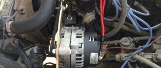
Most VAZ 2107 cars of the carburetor and injection type are equipped with generators with built-in charging relays. The charging relay on such VAZ 2107 vehicles is located directly on the side of the generator opposite the pulley.
To maintain an acceptable battery charge, the alternator requires 13.6 to 14.6 volts of power. The voltage regulation circuit is carried out using an electrical circuit, which is located on a printed circuit board (chocolate board) or in the form of a single semiconductor module (tablet) with brushes. The switch located inside the generator is usually not able to adequately respond to the ambient temperature due to its location close to the running engine. The built-in relay is sometimes replaced with a three-level voltage regulator, which is due to the greater efficiency of the product due to manual adjustment of the output voltage.
How to check the charging relay on a VAZ 2107
If you suspect a faulty operation of the voltage regulator relay, then you must first check the voltage at the battery terminals with the car running. The power supply must be no lower than 13 and no higher than 14.6 Volts. The reasons for such increased or decreased voltage can be caused by the following factors:
- charging regulator malfunction;
- failure of the generator itself;
- lack of contact in the electrical connections of the battery or generator.
To check the serviceability of the chocolate bar, it is necessary to remove it from the generator. This must be done by unscrewing two bolts.
To check the serviceability of the product, you need to connect a voltmeter or test lamp, as well as an adjustable power source of 12-22 Volts. You can use a power supply with a variable resistor. The control check of the regulator relay is carried out by connecting the minus wire from the regulated source to ground or terminal “Ш”. The positive wire of the power supply must be connected to terminal “B”. A voltmeter or lamp is connected to the brushes or relay output. If the product is in good working order, then when a voltage of 12 to 14 Volts is applied to it, the light will light up or the voltmeter will show similar values. If you apply power above 16 Volts, the light should go out. If the light bulb is constantly glowing, you can judge that the product is broken. The absence of a light bulb indicates a break in the relay. In both cases, the regulator cannot be repaired, so it needs to be replaced.
How can you check the product for serviceability without removing it from the car? To do this, you need to connect a voltmeter to the battery terminals, and then start the engine. If the voltmeter readings are below 12.7V or above 14.6V, then the probability of the chocolate bar failing is 95%. Replace the product with a new one, then check the voltage.
Checking individual nodes.
If problems are detected in the operation of the electric generator, it is necessary to check individual components in order to decide on further actions - the ability to continue driving (if a breakdown occurred during a trip), the need for repair or complete replacement of the device.
In general, if problems arise on the road, it is recommended to turn off the generator and get to the nearest service station (on the battery, if there is enough charge) or in tow (tow truck). Operating a vehicle with a faulty power supply can result in serious problems (for example, complete failure of the on-board electronics).
Mechanical check.
At first glance, wear of bushings and bearings seems to be the least serious problem. However, their wear leads to increased friction, overheating of the device, and additional (albeit insignificant) engine power take-off. Distortions, destruction of parts, complete jamming of the rotor, and breakage of the drive belt are possible.
The integrity of the drive pulley is checked visually. To check the condition of the bearings (bushings), it is enough to rotate the rotor manually and try to move it perpendicular to the axis of rotation. When parts wear out, a characteristic sound is heard and the rotor rotates with significant resistance. Play perpendicular to the axis is a sign of significant wear and indicates the need to replace parts.
Brush unit.
To check the brushes, it is enough to dismantle the brush assembly and visually inspect the parts. If the brushes are severely worn, it is recommended to replace them. Before installation, you should check the condition of the collector.
Collector (slip rings).
The node is responsible for supplying the excitation voltage. Accordingly, significant wear of the collector rings leads to disruption of generation and instability of the output voltage. When brushes slide over the surface of worn rings, sparking is observed, which becomes a source of interference and malfunction of the on-board electronics.
The condition of the rings after dismantling the brush assembly is determined visually (by examining the surface) or by touch. A sign of significant wear is the sparking mentioned above.
The problem can be eliminated by grinding the surface of the collector rings (however, this cannot be done indefinitely - the thickness of the conductive layer is limited, and eventually the rotor will need to be replaced).
A short circuit between the rings is possible when current-carrying bridges are formed (from graphite or metal dust deposited when the brushes and rings operate). It can be eliminated by cleaning the surface of the collector assembly.
Condition of the windings.
In an electric generator it is possible:
- Breakage of stator phase windings, field windings.
- Interturn short circuit;
- Breakdown to the body.
Faults can be partially diagnosed using a tester. The device is used in resistance measurement mode, the measurement limit is units of ohms. Before measurements, disconnect the connected conductors and remove the brushes.
Checking the field winding:
- Measure the resistance between the collector rings. In the case of a serviceable winding, the value is 2.3-5.1 Ohms (nominal resistance 4.3 Ohms). “Infinity” on the ohmmeter indicates a break; a lower value is an indirect sign of an interturn short circuit.
- Check the winding for an interturn short circuit. 12 V is supplied to the slip rings from the battery through a multimeter turned on in DC measurement mode (limit more than 5 A). Readings of more than 5 A indicate the presence of a short circuit between the turns.
- Check for insulation breakdown by measuring the resistance between one of the collector rings and the housing. A value of more than 50 kOhm is a sign of breakdown.
It is impossible to carry out similar checks (except for testing for breakdown) without removing the device. First, you need to disconnect the winding leads from the rectifier bridge. Secondly, their resistance is low, about 0.3 Ohm, and it is difficult to measure it without precision instruments.
Rectifier bridge.
Failure of rectifier diodes is a fairly common malfunction that poses a serious danger. The breakdown of the diodes is equivalent to a short circuit at the output of the electric generator, creating shock current loads for the windings, overheating, insulation failure with further failure.
A detailed check and identification of a burnt-out diode can only be carried out by removing the bridge. However, it is possible to draw conclusions about its performance without dismantling the device.
- Disconnect the wires and dismantle the brush assembly.
- A tester (multimeter) measures the resistance between terminal B+ (30) and the housing. The measurement limit is 1 kOhm, “positive” probe at B+ (30). If the diodes are not broken, the measurement result is infinite resistance. Low resistance indicates a breakdown of the bridge strut (the most common fault).
- Change polarity (swap tester probes). The readings should correspond to a pair of open diodes (maximum within 200-500 Ohms).
- The additional rectifier that supplies the relay-regulator is checked in the same way - instead of terminal B+ (30), the probe of the device is placed on contact D+ (61).