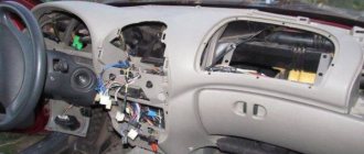
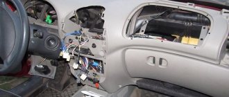
How to remove the instrument panel on a VAZ 2114 with your own hands
What is a torpedo? In short, this is the dashboard. The word “torpedo” came to us from the West and has now become firmly established in the everyday life of domestic car enthusiasts.
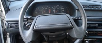
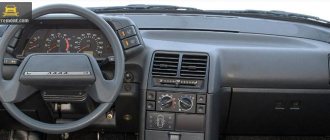
Dashboard of a VAZ 2115 car
The instrument panels on the VAZ 2113, 2114 and 2115 are almost the same. These are complex collapsible structures made of metal with plastic inserts. In addition, in the panels of this line of VAZ models, engineers actively used polymer film, which covered most of the controls.
Diagram of the main elements of the VAZ 2115 dashboard
Peculiarities
VAZ 2114 cars have many innovations compared to 2109, in particular, this concerns electrical wiring.
Whether it is an injector or a carburetor, the wiring diagram for the VAZ 2114 is located in:
- vehicle interior;
- in the engine compartment;
- behind the car body.
It should be noted that carburetor VAZ 2114 were produced only from 1997 to 2000, then they were equipped with carburetors from the VAZ 2108.
But new engines have a more powerful ignition system; accordingly, the electrical control circuit is also characterized by certain features, for example:
- There is a new harness for connecting to the ignition module terminal. This component sends signals to the spark plugs through high-voltage wires.
- Another harness was added to allow mounting of the switch.
- Additional wiring has appeared to connect the adsorber valve to the injection system controller.
Wiring and equipment diagram 2114
Many VAZ 2114 car owners mistakenly believe that thanks to the ignition module, they don’t have to use a coil. In fact, this device is equipped with two coils and two switches. One of the coils transmits the signal to the first and fourth cylinders, and the second - to the second and third.
The equipment system of VAZ 2114 cars with an injector engine has undergone certain innovations not only due to the addition of new electrical equipment, but also as a result of modernization of the car as a whole:
- it is possible to install a heated side mirror device;
- you can connect the front seat heating system;
- VAZ 2114 car owners can install PTF, etc.
Engine compartment
So that a VAZ 2114 with an injector engine can operate on a lean combustible mixture, the car is equipped with:
- forced gasoline injection system into each individual cylinder;
- connecting an improved ignition system characterized by higher power;
- added ECM - injection engine control system.
BC display on a car dashboard
As is known, to ignite a lean combustible mixture there must be a more powerful spark transmitted through high-voltage explosive wires. A spark is transmitted through the explosives of the VAZ 2114 injector when the piston is located at top dead center. This control and connection scheme via high-voltage wires was implemented thanks to the installation of the module.
The operating principle of the device is as follows:
- a generator is used to generate alternating electric current;
- the current passes to the control unit, where it is converted into direct current;
- further, the current flows to the windings of the coils in accordance with the control circuit;
- the secondary winding begins to generate high voltage for transmission through high-voltage explosive wires;
- then, through the same high-voltage explosive wires, the voltage passes to the spark plugs.
Salon
As for the interior, the manufacturer replaced the center console in the VAZ 2114, which has certain differences:
- there is no longer a glove compartment in the upper part, it is installed lower;
- the dashboard was replaced;
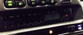
- an on-board computer appeared in the VAZ 2114.
Diagnostics of resistance with a multimeter
As a result of such changes and the replacement of old elements with new ones in the VAZ 2114 with an injector engine, the control circuit and wiring connections have also changed:
- another harness appeared for connecting the on-board computer;
- a sensor for monitoring the temperature level outside the window has been added, which is mounted in front of the radiator;
- A voltmeter relay has been added.
In addition, another block of wires was added to the control circuit to control the power windows.
Having once read an article on one of the sites about replacing the instrument cluster (hereinafter referred to as KP) of a VAZ 21083 with a “high” panel with a combination with 2110, I decided to do the same in the version with a “low” panel. I also found a description of the alteration itself. At first glance, everything seemed as simple as shelling pears, however, having taken it seriously, it turned out that the 2115 dlski does not fit into the visor of the standard instrument panel, although it coincides exactly in dimensions with the 2110.
Minuses:
- no suitable visor! You either need to do it yourself, or buy a decorative plastic overlay for the “low” panel and adjust everything to it, as I did;
- you need to cut the front panel itself in order to “recess” the gearbox into it and put the trim on top, because the cover was intended for the standard 2108 gearbox, it also needs to be cut and bent, and fiddling with plastic is quite a troublesome task.
- There will no longer be such useful instruments as a voltmeter and an econometer.
Pros:
- built-in clock with LCD indicator;
- built-in LCD outdoor temperature indicator with ice warning function;
- well, a very nice backlight that cannot be compared with the standard 2108,
- there is a tachometer, and the movement of all the needles is smooth, without jerking (thanks to the stepper motors used)
By the way, in addition to the 2115 gearbox itself, you also need to acquire a speed sensor. There are three varieties: 1. GM (with an American standard round plug), 2. domestic with a plastic shaft, 3. domestic with a metal shaft.
You should take only the third type, because the plastic shaft softens from the heat of the gearbox and flies very quickly, and for GM it is difficult (and most importantly expensive) to buy a mating part of the connector. Do not forget to look for the inscription “6 imp/revolution”, because The sensor for the trip computer looks exactly the same, but gives 10 pulses per revolution. If you want to implement the function of measuring the outside air temperature, you also need a temperature sensor. I recommend the VDO sensor, it has the smallest error. There must be a block with wires with it!
Step one: redo the electrical
Using a small screwdriver, remove the terminals from the blocks leading to the dashboard and shuffle them according to the following table.
| Combination 2108 | The wire | Chain | Combination 2115 | ||
| Block | Terminal | Block | Terminal | ||
| red | 9 | TO | Counter. side light lamp | white | 6 |
| red | 1 | AF | Counter. high beam lamp | red | 11 |
| white | 7 | GP | Counter. fuel level lamp | — | — |
| red | 6 | RG | Counter. brake level lamp liquids* | red | 7 |
| red | 7 | KG | Counter. parking brake lamp | white | 11 |
| red | 13 | KB | Counter. battery charge lamp | white | 12 |
| red | 5 | SG | Counter. oil pressure lamp | white | 13 |
| red | 11 | GB | Counter. emergency lamp alarm | red | 12 |
| red | 12 | JV | Counter. choke opening lamp | white | 7 |
| red | 4 | GP | Counter. turn signal lamp | — | — |
| ** | ** | MS | - // - left | red | 5 |
| ** | ** | G | - // - right | red | 6 |
| red | 2 | Salary | Counter. glass heating lamp | *** | *** |
| red | 8 | VERY | Counter. fog lamp Sveta | *** | *** |
| white | 4 | B | Instrument lighting**** | red | 4 |
| ***** | OZ | Tachometer input high voltage | white | 3 | |
| ***** | WITH | Speed sensor | red | 9 | |
| white | 2 | ZB | Coolant temperature sensor | white | 5 |
| white | 13 | RP | Fuel gauge input | red | 10 |
| white | 12 | ABOUT | +12V | white | 10 |
| white | 9 | OG | +12V | red | 2 |
| white | 8 | BW | Ground, input 2 temperature sensors | red | 3 |
| red | 10 | H | Weight | white | 1 |
| white | 5 | H | |||
| — | — | — | temperature sensor input 1 | red | 1 |
| — | — | — | const 12 V (from terminal 30 of the ignition switch) | white | 4 |
Notes *- it is necessary to connect +12V to the brake fluid level sensor instead of ground (black wire), for example, from pin 4 (blue-red wire) of the switch or from pin 4 (also blue-red) of the EPHH control unit **- diverted from the corresponding terminal of the hazard warning switch in the console ***- The wire is carefully released from the harness and inserted back into the console, where it is connected to the corresponding warning lamp in the switch housing.
Or it is carefully wrapped with electrical tape, and the wiring from the switch itself is routed to the indicator lamp. For more details, see below **** - in order for the instrument lighting to turn on when the ignition is turned on, I have a “plus” applied to the “positive” contact of the instrument illumination brightness adjustment resistor from terminal 15/2 of the ignition switch, the old contact is insulated. Next, a ***** harness of four wires is knitted - gray, blue and purple, black and orange-green. Black (ground) goes from terminal 3 of the speed sensor connector to terminal 3 of the red combination block. Blue with purple (+12V) - from terminal 15/2 of the ignition switch to terminal 1 of the speed sensor. Gray (speed sensor output) - from terminal 2 of the sensor to terminal 9 of the red combination block. And finally, the orange/green goes from the ignition coil “K” terminal to terminal 3 of the white combination block. The harness is passed in place of the speedometer cable and is sealed with a rubber passage plug. The econometer tube is unscrewed from the manifold along with the fitting and the hole is plugged with a copper bolt.
Step two: implanting the dashboard into the panel
Having made sure that it wouldn’t fit into the window from the old gearbox, I had to take a hacksaw and slowly expand the window on the right and left. It was immediately discovered that under the layer of polyurethane foam that covered the panel, there was also a sheet of metal, which probably should give the panel rigidity. Carefully expanding the panel window, we leave small “ears” made of this metal so that later, bending them as required, drilling holes in them and securing the gearbox with self-tapping screws through the side holes. I expanded it like this: I used a hacksaw blade to make small horizontal slits in the corners of the panel window and several additional slits, not forgetting about the lugs for future fastening. Then, with the effort of his hands, he tried to bend the resulting fragments down. I broke out the excess. The window also had to be expanded from above to ensure an acceptable tilt of the gearbox. We don't touch anything at the bottom. I also had to cut off the upper lugs of the gearbox, which interfered with the normal installation of the lining.
Step three: installing decorative trim
You need to recess the gearbox into the panel so that the cover can sit on top of it normally. I strongly do not recommend using covers made of fiberglass. They cannot be bent using heat. Fiberglass does not melt even in a fire, and it is difficult to cut. We cut out the upper part of the lining according to the shape of the gearbox glass, the lower and side parts should be brought out under heating so that with subsequent trimming the shape of the gearbox glass is obtained. Under heating, we try to move them as far as possible in opposite directions in order to expand the window of the lining. The plastic was heated using a Chinese gas burner (a tiny blowtorch), which provided good spot(!) heating. We do not recommend heating over a gas stove, because... plas. Having stopped heating, we immediately try to “bend” the walls inward with our fingers, thereby expanding the window. Any excess that interferes with fitting is immediately trimmed with a blade. The situation was worse with the lower left and right corners. They are important because lamps indicating external lighting and suction could be hidden behind them. I warmed more of the side of the corner, and not the bottom, because otherwise the lower part of the lining will “float”. There were some minor mistakes; I tried to correct the inaccuracies in the reverse order. Next we paint the entire trim with matte black paint. To hide the defects in trimming the trim, I placed a seal from the rear light of a VAZ 2105/2107 around the perimeter of the cut window. The trim is attached with self-tapping screws from the ends of the panel, and the front part of the trim is secured with double-sided tape. As practice shows, this is enough. You can also screw the front part with self-tapping screws and paint their heads black, but, to put it mildly, this will not add any special aesthetics.
I indicate the operation of fog lights, flashlights and rear window heating in the following way: we replace all these buttons with similar ones, but with internal illumination, and not with light bulbs, with LEDs of the required size and color with a 2 kOhm resistor, and remove the green filter. We do the same with the outdoor lighting switch, replacing the light bulb with an LED. Small printed circuit boards with soldered current-limiting resistors and red LEDs are installed in the places provided in the console next to the buttons so that the light from the desired LED falls directly on the light guide ('eye') of the desired button. The switching wires are connected through the connector to the contacts in the block of the desired button, to which + 12V is supplied after switching on.
We will not change the hazard warning button, but simply disassemble it and insert a red LED into it (with a resistor, of course). Don’t forget to display the contacts to which power will be supplied (see how this is done in the backlit button). Next, you need to connect all the lights in parallel with the lights on the outdoor lighting switch, while observing the polarity. Otherwise, the LEDs simply will not light up.
Step four: installing an outside temperature sensor
Information about the outside temperature is very relevant, especially in the off-season at the first frost. For the most part, it was for the sake of this option that the choice fell on KP 2115, and not from 2110. We install the sensor so as to isolate it from direct sunlight, heat from the engine compartment, from heated asphalt and ensure that it is blown with oncoming air. In the “eighth” bumper, this place is in the lower part on the right side of the cutouts for cooling the radiator. To mount the sensor, you need a bracket made of sheet metal 0.8...1 mm thick, sketch below.
We bring the wires from the sensor into the engine compartment and lay them along the headlight harness, then we lead them into the interior to the instrument cluster, where they are connected to contacts 3 and 1 of the red block. Another option: since there is only one wire “ground”, you don’t have to pull it across half the car, but screw it in any convenient place in the engine compartment. If all connections are made correctly, then when the ignition is turned on, the left display will show the outside temperature value, otherwise - “- 40 C”.
We count expenses
- Instrument cluster VDO 2115 — 2400 rub.
- Speed sensor - 160 rub.
- Temperature sensor - 150 rub.
- Decorative overlay 2108 — 600 rub.
- Buttons with internal backlight - 3x35=115 RUR.
- Wires, connectors and pads for buttons - 50 rubles. Plus the cost of the work, if you don’t do something with your own hands (I got 540 rubles)…
Is it worth paying that kind of money for the interior lighting of the instrument cluster? There is, however, a cheaper option: do not install the trim, but try to make the visor yourself, and so that its height and mounting fastenings coincide with the standard ones.
What's inside the cabin
Replacing the power unit will also require replacing the interior wiring.
Many owners combine this process with replacing the instrument panel with a modern one:
- the “high” panel from the VAZ 21099 fits without modification;
- The “LUX” panel from the VAZ 2114 model is suitable with minor modifications.
Tip: there are a lot of videos on the Internet that describe in detail the process of finalizing the panel. Read them all carefully before starting work on your car.
Photo gallery: tuning the interior of the “nine”
Modifying the seats allows you to change not only their appearance, but also improve the fit
Installing a dashboard from another car allows you to make the interior more modern
Improved interior lighting provides additional comfort not only for the driver, but also for passengers
Sports seats allow the driver to feel as comfortable as possible when tailoring the car for sports.
Upgrading a torpedo with your own hands allows you to build acoustics or multimedia into it
The introduction of additional devices makes vehicle operation more comfortable, giving the driver additional information about the status of important components and systems
Illumination of the passenger and driver's feet adds some zest to the ordinary interior of the Nine.
The introduction of LED lighting into the glove compartment is one of the interior tuning options
Modern floor mats are also an option for upgrading the interior of the VAZ 2109
The tuned panel combined with a sports steering wheel makes the car different from others
Tuning the interior of a VAZ "nine" is a fascinating process. Depending on the wishes and financial capabilities of the owner, the interior can be changed beyond recognition. By replacing the interior finishing materials with modern ones, the car will be pleasant for both the driver and passengers. In addition, the upgrade can be done with your own hands without the use of special tools.
How to install a Europanel on a VAZ 2109
Task: install a Europanel on a VAZ 2109 carburetor
What is needed for this:
1.Euro-torpedo 2. Instrument panel 3. Wiring under the torpedo 4. Fuse block 2114 (it has 9 relays)
2114-3722010-60, as in the picture
5) Speed sensor (since there used to be a cable)—the sensor needs to be taken “6 pulse turn”
6) Steering column 2114 (with adjustment) 7) Wires that will come from the speed sensor 8) Cables from the VAZ 2114 stove, because old short ones 9) A pair of 4-pin relays 10) Current control 11) Ignition switch with 14k
Disassembly And so you removed the top, first we take out all the rubbish, rubbish, etc. from the car, then we climb under the column, we see the bolts for the column, you can remove it (I removed it because I made a Shumka of the whole muzzle, and there is more room without it)
Installation of a multimedia system and other elements
With the spread of touch screens, they have become quite often used in the production of multimedia systems that are installed in cars. Of course, you can purchase a GPS navigator that will be mounted on top of the panel. But still, this design option is impractical, as it takes up a lot of free space and impairs visibility.
If desired, you can implement a multimedia system into the torpedo. For this:
1. Select a multimedia system. 2. Find out its exact dimensions. 3. We mark the area on the dashboard. 4. We cut out the plastic. 5. Install the multimedia system. 6. Connect the system. 7. We carry out decoration.
In the same way, you can install control units for additional functions, for example, self-installed fog lights or interior lighting. In order to significantly simplify the work, you can buy a disassembled control panel from another car, also mark the location on the dashboard and cut out a place to install the panel.
In general, we can say that it is possible to modify a factory torpedo almost beyond recognition.
How to connect and install
It is recommended to install and configure any musical device on the VAZ-2114 in accordance with generally accepted rules. Only in this case will the equipment work efficiently and perform all its functions.
Are you a car driver?! Then you can take this simple test and find out. Go to test »
Connection
To connect a radio to a VAZ-2114, just familiarize yourself with the procedure provided for any similar model (2115, 2109). The only difference will be in the location of one or another wire.
Connect the radio using this method:
- Connect the musical equipment connector to the positive and negative poles of the power source (battery). In this case, the cigarette lighter plug can be used for switching.
- Remove the cables from the speakers and connect them to the corresponding outputs on the device plug.
- As soon as the wiring is connected, all potentially dangerous places are isolated using special tape. You can additionally protect the cable from accidental contact and the negative effects of moisture by using a corrugated tube.
- An antenna is installed on the inside of the windshield or roof of the vehicle.
- The cable running from it to the dashboard is laid under various parts of the car's interior trim.
- The wire is connected to the radio directly or through an adapter.
Scheme
In order to check the correctness of the connection, it is necessary to draw up its diagram. With its help, you can identify mistakes made and correct them as quickly as possible.
The diagram should indicate the location of the following wires:
- Red. It should go from the radio to the ignition switch.
- Yellow. It is connected to the positive terminal of the battery and the corresponding connector on the back panel of the connected device.
- Blue. This cable must be used to connect the speaker system to the antenna.
- Green, purple, gray, white. All these wires should be routed to the two front and rear speakers.
- Black. They connect the radio to the negative pole of the battery.
Installation
Installing a radio on a VAZ-2114 is a difficult task, which is recommended to be performed only after careful preparation. Otherwise, you can easily make a mistake that will not allow the device to function normally.
What can be changed in the electrical circuit
Let's figure out what exactly car owners undergo alterations.
Moreover, we will indicate only those alterations that are not prohibited by the manufacturer and current regulations:
- Installation of a new instrument panel;
- Alteration of internal (interior) lighting;
- Installation of additional turn signal indicators in the rear view mirrors;
- Installation of additional headlights (fog lights);
- Installation of an acoustic and multimedia system;
- Immobilizer installation.
For reference: the visual differences between the standard panel and the “high” one are that the radio compartment is moved to the level of the dashboard. Accordingly, the wiring on the VAZ 2109 under the instrument panel must be replaced.
Interior modifications
Many owners come to mind with the desire to improve the lighting in the car interior.
Let us remind you that inside a passenger vehicle there are several places equipped with lighting sources:
- The salon itself (interior lighting);
- Glovebox;
- Cigarette lighter;
- Instrument panel (instrument cluster lamp and symbol lamp)
If you, as the owner, like a high panel in the cabin, then you cannot do without replacing the standard wiring. Because the:
- Control devices have a different location on the panel;
- The standard length of wires is not enough;
- Terminal blocks may also differ.
Accordingly, without replacing the electrical wires it will not be possible to use:
- instrumentation;
- on/off buttons for various devices.
As for making changes to the instrument panel lighting, today there are sets of special lamps on sale along with the wiring with which they are connected to the car’s electrical network.
You can install such kits yourself; it is only important to adhere to accuracy and safety rules.
Advice: carry out all electrical wiring replacements and connecting instrumentation only with the battery disconnected.
What's on the dashboard
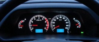
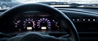
Standard tidy 2114 includes the following elements:
- coolant temperature indicator;
- tachometer;
- left turn indicator;
- right turn indicator;
- speedometer;
- fuel level;
- fuel reserve light;
- side light bulb;
- brake system light;
- high beam headlight bulb;
- button to reset current readings;
- odometer;
- hazard warning lamp;
- "check engine" light;
- watch;
- battery charge light;
- parking brake light;
- oil light;
- reserve.
Each of these electronic elements is connected to the corresponding contact on the common panel. Which one, and to which one exactly – we’ll look at it below.
Instructions for installing a new panel
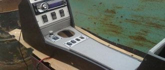
If you want to replace a low tidy with a more advanced, high one, then in any case you will have to change the entire center console.
Removal and installation instructions look like this:
- First, you need to turn off the power to the on-board network; to do this, disconnect the battery, remove the steering wheel, as well as the steering column switches and the ignition switch. You will also need to disconnect the ignition relay.
- Next, unscrew the two bolts that secure the control panel visor and remove it.
- Now you need to compress the spring and remove the shield itself from the center console. Disconnect all wires and connectors connected to the dash, including the speedometer cable, the econometer hose, and the odometer cable. After this, the tidy can be moved to the side.
- Then remove the regulator from the hydrocorrector of the optics light, the tidy light switch knob, as well as the interior heater and fan regulators. To do this, pull the controls towards you.
- After this, unscrew the two bolts securing the center panel trim on the sides; the trim itself can be moved towards you. Then you need to disconnect the connectors.
- Now the key in the lock should be turned to position “0”, this will disable the anti-theft system. A connector with wires is connected to the lock itself; it must be disconnected. Next, unscrew the two nuts and two bolts, after which you can remove the steering column pipe with the switch.
- Remove the choke handle located under the instrument panel. Pull it towards you so that you can feel the pull. You need to unscrew the two bolts that secure the damper guide rod, after which the choke can be removed.
- Now you can unscrew four more screws that secure the heater control panel in the car. Unscrew the bolts located on the side of the shield on both sides. Also unscrew the lower console mounting bolts with nuts that secure the control panel lighting switch and the optics hydraulic corrector. To do this you will need a 22mm socket wrench, it must be high.
- After completing these steps, you need to unscrew the bolt that secures the center console in the glove compartment. Then all you have to do is unscrew one bolt at a time on each side securing the center console. The console itself can then be dismantled.
- As for installing a new high panel with tidy, this process does not present any particular difficulties. All dimensions at the mounting points on the body are the same, but this procedure also has its own characteristics. To install your new console, you will need the appropriate wiring harness. If you use an existing harness, then you will need to rearrange the terminals in it, taking into account the connection diagram. In addition, it will be necessary to change the cables leading to the heater to longer ones, the same applies to the speedometer cable. If you are installing a new console, you will also need other roof pillar side trims, these must be installed before you install the console. Since the new dashboard will not use a flow meter, the tube from it will need to be plugged. In addition, the signal to the tachometer will need to be supplied from wire K on the coil, which is connected to the speed sensor cable bracket.
- Immediately before installation, you should reassemble the new console, and wrap the connection points of the blowers with electrical tape and, preferably, glue them with foam rubber or anti-creaking agent. It is also necessary to change the foam rubber of the heater, since the old one will no longer be able to perform its functions. Also make sure that the choke can close completely and remember that the cable from the new speedometer should be installed before you install the console. The assembly procedure begins with laying a new wiring harness and connecting all connectors. Before you finally assemble everything, turn on the dashboard and check how all the indicators and gauges work. After this, the console can be put back in place.
Installing a torpedo from another car
A significant modification can be called the installation of a torpedo, which is intended for another car. Such work is carried out extremely rarely, as it is difficult to perform. Its features include:
- The panel must be selected according to the width of the cabin, otherwise it will not become simple even after modification. At the same time, attention is also paid to the height. For example, SUVs have a higher dashboard, which will not fit into the car in question. Most often they choose torpedoes from foreign cars that were produced in the last millennium. This is due to the fact that they can be found at an affordable price when disassembled, and modifications may be insignificant.
- All elements of the front part will have to be redistributed. Particular problems arise with the location of the stove and steering column. If these elements do not significantly coincide in location, then significant changes must be made to the design of the torpedo.
- In any case, you will have to create new seats and fasteners on the body, since it is more difficult to change the torpedo. This moment determines the need for precise marking, as well as welding, creating holes, and so on.
- Many problems arise if the panel does not fit the width of the body. It is quite difficult to shorten a torpedo qualitatively, but it is still possible. After this, you will have to use additional decorative elements to close the seams.
