Hello. First, the left turn signal stuck (the entire left side), I turned it off by disconnecting the battery terminals. At the service station they did the alteration without removing the TsBKE, now the right side, all the turn signals and the emergency lights do not work. Is it possible to solve the issue without completely changing the CBKE?
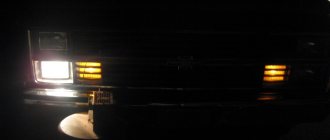
It happens that some kind of breakdown occurs on the car, after which the turn signal constantly lights up. Priora is also not unfamiliar with this problem. The glow is constant, even when the alarm is turned on. In this case, the failed turn signal continues to light steadily, while the other lights blink synchronously.
Thorough examination of technical condition
To diagnose and eliminate the malfunction, you should visit a service station. If you have experience and the necessary equipment, you can do everything yourself. This will require 1-2 hours of free time. Among the most common causes, car mechanics identify a short circuit or physical wear of the mechanism. Regardless of this, the procedure is as follows:
Possible causes of the malfunction include damage to the wiring leading to the electrical package control unit. One of the most common examples: an incorrectly installed radio tape recorder pinches the wires, which leads to a short circuit. Do not lose sight of the wiring connecting the light bulbs and the CBKE. You can verify that the circuit is working properly as follows:
Notes on implementation of schemes
Let us immediately note: if there are no window lifters, the second diagram will not contain parts K2/K3. Then you only need to cut one wire. Sometimes only the rear windows are missing. This means that relay K3 is excluded. And the diodes connected in parallel with the winding can be absolutely anything.
Now we list the requirements for an element called “relay”:
- Operation voltage – 12 Volts;
- Switching current – 10 A or higher;
- The current consumed by all relay windings should not exceed the value specified in the instructions for the signaling. Usually it is 200-300 mA.
It is the last requirement that is often violated.
In order for “scheme 2” to work, it is necessary not only to assemble it, but also to program the main unit: you need to enable the “2-step unlocking” option. And be that as it may, control impulses cannot be made too long. Use values of 0.7-1.1 seconds.
Diagnosis and elimination of complex faults
Stuck relays and damaged diodes are breakdowns that require careful diagnosis and labor-intensive replacement. To carry out diagnostics, it is necessary to disconnect all points where the car alarm system is connected to the electrical package control system. If, as a result of these actions, the turn signal lights up in normal mode, then it is necessary to replace the damaged section of the wiring.
It is more difficult when, even after these manipulations, the turn signals of a passenger car are constantly on. Then all attention shifts to CBKE. In particular, we are talking about fuse F31, which is subject to external influences: voltage changes, moisture ingress, etc. An additional signal that the problem is related to it will be poorly functioning window regulators.
In this case, you must contact an authorized service station for diagnostics and replacement.
This will require special equipment. If work is performed in a garage, there is a high risk of further deteriorating the technical condition of the vehicle.
Tips for motorists
When the driver of a Lada Priora passenger car finds himself in a situation with direction indicators that have refused to work, then in order to get to his home or place of repair, he will have to remember the Rules of the Road, which says how to duplicate the direction indicator signals using his left hand.
The simplest malfunction leading to the failure of the turn signals is the burnout of the filament in one of the lamps. In this case, the turn signal lamp installed on the instrument panel begins to blink at double frequency. In this situation, the driver needs to stop, get out of the car and determine where he will have to change the faulty turn signal lamp. When replacing a lamp, he must remember that it must be exactly the same power as the burnt one.
But other turn signal malfunctions are much more difficult for the driver to deal with, since their operation is controlled by the turn signal switch located inside the electrical package controller, and without knowledge of electrical engineering you are unlikely to be able to find a malfunction there. The only thing the driver himself can do is replace the faulty power package controller with a new one. To find it, you will need to remove the lining on both sides of the floor tunnel, but before you begin this work, disconnect the battery by removing the negative terminal.
The direction indicators may also fail to function due to failure of the steering switch. The most innocent malfunction under the steering switch is the inability to independently return it to the neutral position. In this case, the driver can continue to operate the Lada Priora car, although he will need to remember to turn off the turn indicators after performing the maneuver.
Fuses and relays in Lada Priora, electrical diagrams
Lada Priora is another car in the line of new VAZ cars, which is gaining popularity among segments of the population. External similarities with the 10th model attract the attention of young people; the relatively low price is also a reason for purchase for most car enthusiasts. Along with the growth in popularity, the owners of this model are gaining experience in repair and maintenance, which is becoming more and more every year.
If your Priora has electrical problems, do not rush to get upset; first, check the fuses and relays in your Lada Priora. These are the ones that will be discussed in this article.
Priora turn signals and instrument lights do not work
- Registration
- Entrance
- To the beginning of the forum
- Forum Rules
- Old design
- FAQ
- Search
- Users
I’m not a telepath, and I don’t know what could be wrong with him!
Devices that operate when the ignition is on fail, so IMHO look first at the ZZh, especially if something else that feeds after the ZZh doesn’t work!?
I’m not a telepath, and I don’t know what could be wrong with him!
Devices that operate when the ignition is on fail, so IMHO look first at the ZZh, especially if something else that feeds after the ZZh doesn’t work!?
I’m not a telepath, and I don’t know what could be wrong with him!
Devices that operate when the ignition is on fail, so IMHO look first at the ZZh, especially if something else that feeds after the ZZh doesn’t work!?
Except for the stove, everything listed above works when the ignition is turned off, and maybe now the stove too?
Then take it apart again and check how it is!?
I am again leaning towards the ignition switch, since the alarm could have been triggered by the spontaneous ignition switching on, and the engine would not stall due to the fact that it could not turn off!?
[quote=”Karzhimant”]Take it apart again then, and check how it’s doing!?
quote](CHY) is this a mounting block?
Then take it apart again and check how it is!?
I am again leaning towards the ignition switch, since the alarm could have been triggered by the spontaneous ignition switching on, and the engine would not stall due to the fact that it could not turn off!?
Then take it apart again and check how it is!?
I am again leaning towards the ignition switch, since the alarm could have been triggered by the spontaneous ignition switching on, and the engine would not stall due to the fact that it could not turn off!?
Source
Fuse box in the passenger compartment of VAZ-2170, -2171, -2172
The fuse box in Priora is located at the bottom of the dashboard, on the left side of the steering wheel. To get to it, you need to open the cover, which is held on by three latches. Rotate each locking knob 90 degrees and pull the lid down and it will snap open.
Fuses in the interior mounting block
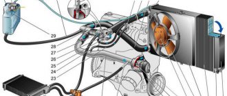
F1 (25 A) - radiator cooling fan . If your fan does not work, check its motor by applying 12 V directly to it from the battery. If the engine is working properly, then most likely the problem is in the wiring or connectors. Check the serviceability of relay K1.
The fan in the Priora usually turns on at a temperature of 105-110 degrees. Do not allow the engine to overheat, watch the arrow of the temperature sensor.
Do-it-yourself repair of direction indicators and hazard alarms
If the turns disappear, as well as the car’s emergency signal, then you can try to solve this problem yourself:
- If the safety element and relay break down, the failed parts must be replaced. If the reason lies in a short circuit, then before replacing it is necessary to check all electrical circuits in which it could occur. Only after the cause of the short circuit and power surges has been eliminated, the devices need to be changed.
- If the hazard warning button is faulty, you just need to replace it. We have already talked about how to diagnose this part.
- As for electrical circuit diagnostics, it is carried out using a tester. If damaged sections of the wire are identified, they must be replaced. When laying them, make sure that the wiring does not come into contact with moving body elements. It is also recommended to additionally insulate new wires to increase the reliability of the insulation.
- If the reason is the light bulbs, then all burnt out light sources must be replaced. In the front and rear headlights, the lamps are changed by removing the protection from the headlights, disconnecting the power circuit from the lamp, as well as unscrewing the light source from the seat and replacing it with a new one. If the lamps in the side headlights do not work, then, as a rule, to dismantle the lighting sources, the lamp itself must be pryed off with a screwdriver, then disconnect the power cord and remove the device.
- If the reason lies in the steering column switch, then this device needs to be disassembled and checked. As a rule, the cause of switch failure is poor contact or abrasion. In this case, the failed switch is replaced with a new one. As for the contacts (no matter where - on connections or buttons), it is advisable to clean them.
- You should also check all the plugs and connectors, because it is quite possible that the problem is poor contact on them. Acidified contacts must be cleaned with a wire brush or sandpaper. If the contacts are burnt out, they will need to be replaced.
Additional block
Additional relays are mounted on a bar and located under the dashboard, near the front passenger's feet. To get to them, you need to remove the right tunnel lining. Next to the additional relays is the electronic engine control unit (ECU).
If its connector interferes with access to the relay, disconnect it by first removing the negative terminal from the battery.
Circuit breakers
F1 (15 A) – main relay circuit, starter interlock.
F2 (7.5 A) – power circuit of the electronic control unit (ECU).
F3 (15 A) – electric fuel pump . If the fuel pump has stopped pumping (this can be determined by the absence of a sound when the ignition is turned on), check together with relay K2. There may also be problems with the immobilizer, it blocks the pump, see information about F20. If the wiring, this fuse and the relay are good, most likely the fuel pump itself has failed. To remove it, you need to disconnect the battery, remove the rear seat cushion, unscrew the cover, ring and fuel hoses, then carefully remove the entire fuel pump.
K1 – main relay.
K2 – electric fuel pump relay . See above about F3.
FakeHeader
Comments 29
I had a permanent short circuit on the left side. Diagnosis: body electronics control unit. They changed it under warranty, but the officials have 11 thousand rubles. with work.
The Central Unit of Body Electronics (CBEC) needs to be replaced; the microcircuits in it responsible for one of the cornering sides are burning out. I had the same thing on my Priora, it was changed at the dealer under warranty. I must say, you were lucky, some of them had their cars completely burnt out because of it. The device itself controls all the electronics, BUT! not protected by anything, not even the simplest fuse for protection. And when the microcircuit inside the block short-circuits, it stupidly burns with a blue flame. They showed me the block removed from my car, the body was badly melted, how it didn’t catch fire is a mystery...
Yeah, I bought a new one, I wanted to change it myself, but they said it was better to entrust this matter to a specialist and not save money. They changed it for me and made an adaptation. In general, everything is fine. ))
The Central Unit of Body Electronics (CBEC) needs to be replaced; the microcircuits in it responsible for one of the cornering sides are burning out. I had the same thing on my Priora, it was changed at the dealer under warranty. I must say, you were lucky, some of them had their cars completely burnt out because of it. The device itself controls all the electronics, BUT! not protected by anything, not even the simplest fuse for protection. And when the microcircuit inside the block short-circuits, it stupidly burns with a blue flame. They showed me the block removed from my car, the body was badly melted, how it didn’t catch fire is a mystery...
Where is he located and not in the know?
I just saw that I was a fellow countryman. )))) A friend had exactly the same problem, they took this comfort unit for 36,000
How to change the turn switch on a Priora
We carry out work when replacing steering column switches, switch connectors, spiral cable drum devices, as well as when removing the steering column and instrument panel. Disconnect the wire terminal from the negative terminal of the battery.
Using a Phillips screwdriver, unscrew two self-tapping screws 1 securing the lower steering column casing to the rear bracket of the electric power steering, one self-tapping screw 4 fastening the lower casing to the connector of the steering column switches, two self-tapping screws 2 and two screws 3 connecting the upper and lower steering column casings to each other.
We remove the lower one (for clarity, the steering wheel has been removed)…
...and the upper steering column housings.
Squeezing the latches (top and bottom) with your fingers...
...remove the left steering column switch from the connector.
Disconnect the instrument panel wiring harness from the left steering column switch. Similarly, remove the right steering column switch. At the same time, we additionally disconnect...
...the wiring harness of the steering column switch from the wiring harness of the instrument panel.
Steering column switches
: 1 — left switch; 2 - right switch Install the steering column switches in the reverse order. If necessary, remove the connector for the steering column switches. To do this, remove the steering wheel (see “Removing the steering wheel”) and the steering column switches.
Using a screwdriver, press the lock of the horn switch wire block...
...and disconnect it from the connector of the drum device of the spiral cable. Similarly, disconnect the airbag wire block from the other connector of the device.
Use a 8-mm socket to loosen the coupling bolt of the connector...
...and remove from the steering column the connector of the steering column switches assembled with the spiral cable drum device.
Using a Phillips screwdriver, unscrew the four screws...
...and disconnect the switch connector and the drum device. Install the connector for the steering column switches in the reverse order. When assembling the connector of the steering column switches with the spiral cable drum device...
...two protrusions of the drum device...
...must fit into the corresponding grooves in the connector hub. We install the connector assembly with the drum device on the steering column.
In this case, protrusion 1 on the steering column pipe should fit into groove 2 of the connector body. We perform further assembly in reverse order.
The steering column switch assembly consists of a connector secured with a clamp to the steering shaft bracket and two switches with levers. The left switch turns on the turn signals and switches the headlights, the right switch controls the windshield washer and wiper, as well as the trip computer in the instrument cluster.
The switches are secured in the connector with latches.
Rice. 10.8. Positions of the steering column switch levers
The positions of the switch levers are shown in Fig. 10.8, the contacts closed in this case are given in table. 10.7.
Table 10.7 Contacts closed at different positions of the steering column switches
* Non-fixed lever positions.
Contact numbers of the turn signal and headlight switch
Problems with the ignition coils
High voltage ignition coils and problems with these components can also cause a warning to appear on the instrument panel. Such problems can be indirectly determined by the characteristic tremors of the car at idle. The car owner can check whether there is current on the coil and whether the contacts of the high-voltage wires are loose. If there are problems with the coils, it is best to replace them as a set. The VAZ 2110 engine has four high-voltage coils, the cost of which is at an affordable level, and every car owner can handle such a replacement.
How to indicate the direction of travel if the turn signals are faulty
In some cases, it is not possible to use turn signals. For example, when they are faulty, blocked by foreign objects, or not provided for by the design. The traffic rules provide guidance in this regard.
- a raised hand indicates the driver's intention to brake.
- a hand extended horizontally to the left warns of the intention to turn left or change lanes to the left.
- an outstretched right arm or a bent left arm at the elbow, looking up with the hand, speaks of the above maneuvers, but to the right.
In addition to these hand signs, there are also unofficial, but no less useful:
- Flashing your headlights to an oncoming driver: there is danger ahead or turn off your high beams.
- A brief activation of the hazard warning lights means gratitude for allowing you into the next row or an apology for a sudden maneuver.
Reviews
Delivery of goods is carried out throughout Russia and the CIS:
1. Russian Post (from 350 rubles and above)
Delivery to all regions of the Russian Federation and CIS countries
2. Transport Companies (from 350 rubles and above)
Delivery throughout Russia and the Republic of Kazakhstan
- TK Energy (nrg-tk.ru)
- TC Business Lines (dellin.ru)
- TC SDEK (www.cdek.ru)
- TK PEK (pecom.ru)
- TK KIT (tk-kit.ru)
3. Pickup
The order can be picked up at the office at Tolyatti, 40 Let Pobedy 38, TD “Malachite”, 1st floor.
The waiting time for sending an order in our online store is approximately 2-7 working days, large orders 7-14 working days. days; color of bumpers, mirrors, body parts, spoilers, etc. 7-14 work. days; sewing covers, upholstery, steering wheels, gear knobs, EVA mats, etc. 7-14 work. days.
During this period, we will send you a tracking number by email. email to track the parcel en route.
Payment can be made in the following ways:
1. Payment to a Sberbank card
You can pay using the SBERBANK-Online application and other Bank applications.
After placing an order, making payment, do not indicate comments , we ourselves will understand by the amount of the order and the name of the sender. After receiving the funds, the status of your order will be changed to paid until 17.00 of the current day, or from 9.00 of the next Moscow time.
2. By bank card
Automatic acceptance of payments using MIR Bank cards, VISA International, Mastercard.
You can also pay with credit cards with a grace period.
To select payment for goods using a bank card, on the corresponding page you must click the “Pay for order by bank card” button.
2. Payment to QIWI wallet 89272115207
3. Payment on Yandex.Money 410013993950891
5. Payment to a bank account for legal entities and individual entrepreneurs (commission 6%)
Send your organization's details to [email protected] for invoicing. After paying the bill, be sure to send a payment order.
4. Cash on delivery of Russian Post (commission from 4%)
IMPORTANT! When sending by cash on delivery, RUSSIAN POST will take a commission for providing the cash on delivery service of 150-300 rubles, and the delivery cost also increases due to the evaluation of the goods.
Cash on delivery delivery is possible only within Russia.
ATTENTION! When choosing cash on delivery, the delivery cost is paid in advance before shipment, for the product itself upon receipt.
The amount of the order by cash on delivery should not exceed 5000 rubles; also, painted parts, goods made to order, covers, upholstery, door inserts, EVA mats, steering wheels, etc. are not sent by cash on delivery. (minimum 50% prepayment).