On all cars of the Tenth Family, the power lines for the lights contain many elements. There are lamp health relays, switches and fuses. Therefore, if the brake lights on a VAZ-2112 do not light up, you need to check the entire chain. But the reason may look simple: sometimes the lamps do not turn on because the socket does not contact ground. Circuits are easy to analyze, but finding the cause of a breakdown is difficult. Let's look into the details.
If one of the lamps does not light, it is simply replaced. See the example in the video - you need a P21 W
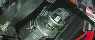
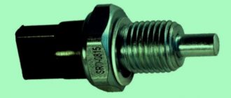
Reverse sensor VAZ 2112 16 valves
Hello friends, we are glad to see you on the DIY car repair website. The reverse sensor of the VAZ 2110 is triggered when reverse gear is engaged and transmits voltage to the light bulb (flashlight), signaling the movement in reverse.
Reverse sensor VAZ 2110
How does the sensor work? After moving the handle to the appropriate position, reverse gear is engaged. At the same time, the power fork presses on the sensor and shorts one of its wires to ground. Result - the reverse lamp comes on.
Wiring test for non-working brake lights (ground test)
Let's look at the basic diagram: the brake lights and the reversing lamps have a common ground pin. If contact with this pin is broken, the reverse lamps will not turn on. Well, brake lights too.
Connector for connecting “internal” lights
On the left side there is a connector through which the wiring goes to the fifth door. The connector has black and red wires. Check the voltages on them. Most often the ground on the black wire does not ring. But maybe the connector itself needs to be cleaned.
Usually, if the ground breaks, another pin is used - the one that is connected to the glass heating coil.
If the “plus” does not come to the red wire, we check the “frog”. It's simple here:
- Disconnect the connector with two wires from the limit switch;
- Using 17mm wrenches, loosen the two nuts: holding the lower nut, rotate the upper one;
By the way, one of the connector terminals receives a voltage of “12 Volts”. Check it!
If all the steps do not lead to results, there is only one thing left: contact a qualified electrician. We wish you success.
Source
Symptoms and malfunctions of the reverse sensor
You put the vehicle in reverse, but the rear lights do not work. There are three options here: the reverse light has expired, the power fuse has blown, or the sensor itself has failed. But how can you check the reverse sensor and make sure that it is the one that is faulty?
Take a few simple steps:
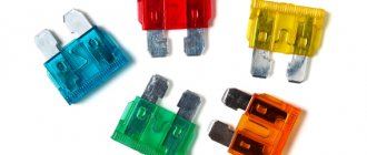
1. Remove the fuse and check its integrity. In the VAZ 2110 it has number 19 (rated current - 7.5 A). The mounting block itself is located under the instrument panel.
2. Make sure the lamp is intact. If there are also no complaints about it, then you can proceed directly to checking the sensor.
We turn on the brake lights forcibly
Relay K1 is successfully replaced with a pad with jumpers. In Fig. 1 just shows its diagram. If there is no such platform, you can temporarily close contacts 4-5. First, check everything mentioned above.
Have an observer watch what happens to the lamps. Press the pedal with one touch and release it. If the lamps do not turn on, check that the fuse is working properly. It's burned out, which means you're looking for a short circuit.
How to and how not to check the “0 Volt” potential
Let’s agree right away that we only work with a voltmeter. Voltage “+12” is caused by connecting one probe to ground. The presence of potential “zero” is checked differently: any of the probes is connected to a terminal with positive voltage, and then the second probe is connected to the wire being tested.
Consider the error: one probe is connected to ground, the second to the terminal being tested, and vol. Here they conclude that there is a “mass” potential, but this is wrong! If the contact with ground is broken, the device will also show “0”. That is, the number “0” does not contain information.
Location and details of checking the sensor
Many novice car enthusiasts do not know where the reverse sensor is located. In fact, everything is simple here. It is necessary to drive the car onto an overpass (pit) and go under it.
A sensor will be installed on the left side of the gearbox (looking towards the rear wheels of the car).
It is very difficult to confuse it with any other unit, because only this element of the gearbox has wires. Now let's move on to the verification.
The sequence of actions is as follows:
- Discard the terminal from the sensor;
- connect a multimeter to the connectors and set the switch to measure resistance;
- move the gearshift knob to the reverse gear position;
- turn on the ignition;
- look at the multimeter readings.
If the display shows a resistance of 0 Ohm and the beeper rings, then everything is normal. If the multimeter shows infinity, then the VAZ 2110 reverse sensor needs to be replaced.
The nuances of replacing the reverse sensor VAZ 2110
Now let's look at how to replace the reverse sensor. Everything is simple here:
Attention! Before unscrewing the sensor, clean it from dirt and dust so that when unscrewing nothing gets into the gearbox oil.
- The machine is already installed on the pit (overpass). Let's leave it that way.
- Remove the crankcase protection.
- Find a small container (you will need it for oil). As a rule, when unscrewing the sensor, a small amount of lubricating fluid spills out.
- Throw wires away from the node.
- Unscrew the sensor and wait for the oil to drain.
- Install a new device.
- Add oil to the required level.
- Return the wires to their place.
- Check the operation of the device.
That's all. Within 10-15 minutes you have checked, replaced the reverse sensor and saved money. Good luck on the roads and of course no breakdowns.
If a malfunction occurs in the reverse light on a VAZ 2110-2112, you must first pay attention to connecting the power plug to the frog itself. If everything is fine there, then there is a high probability that the rear light switch is faulty and needs to be replaced with a new one.
But first of all, it is better to check it.
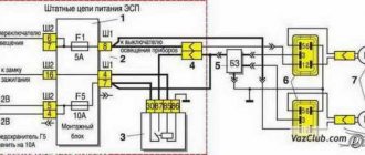
Standard version of the brake light operating diagram
Power is supplied to fuse F17 from the battery, then the current goes to limit switch contact 11, and then, if the limit switch is closed, a circuit is formed with the filament of lamps 7. But note: part of the circuit is relay K1, more precisely, its contacts 5 and 4.
If the brake lights do not light up, on the VAZ-2112, as on all Tens, check one fuse. It is called F17 and is located in the mounting block to the left of the driver.
It is important to know: voltage is always present at one of the fuse terminals. Check it out!
A few words about the “serviceability relay”
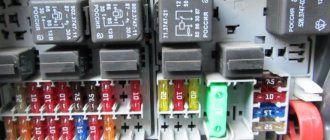
The lamp health relay is called K1, and it is the largest in the mounting block. If you remove this relay, then when you press the pedal you can dial the voltage at terminal 5 (but not 4). Look at the diagram again, and it will become clear what we are talking about.
The largest relay in the block
All relay contacts are numbered. Check the voltage at the block terminals:
- 6 – “mass” potential;
- 2 – voltage “+12”, but only after turning on the ignition;
- 5 – “+12” by pressing the pedal;
- 4 – the terminal rings like a ground tap.
If the potential “0” is not generated at terminal “4,” it means that the lamp filaments are burnt out or there is a break in the wiring. Now consider something else: the ground potential has been detected, but the lamps do not light. This is where suspicions of a short circuit arise.
How to recognize a malfunction of the VAZ 2110 reverse sensor and replace it?
The operating principle of the regulator in question is very simple:
- the driver engages reverse gear;
- when turned on, the plug is pressed against the controller;
- the wire shorts;
- The lamp lights up, indicating that the vehicle is moving backwards.
During the daytime, the driver may not notice the malfunction. But at night it is clearly visible when the lamp does not light up when you engage reverse gear.
In this case, there are 3 causes of failure:
- blown fuse (common cause);
- the lamp burned out;
- The reverse regulator has failed.
In fact, damage to the sensor is much less common than blown bulbs and fuses. Another possible scenario could be damage to the integrity of the wires. Therefore, it is necessary to carry out the appropriate check.
Why do the brake lights on the VAZ-2112 not light up or work, what should I do?
On all cars of the Tenth Family, the power lines for the lights contain many elements. There are lamp health relays, switches and fuses. Therefore, if the brake lights on a VAZ-2112 do not light up, you need to check the entire chain. But the reason may look simple: sometimes the lamps do not turn on because the socket does not contact ground. Circuits are easy to analyze, but finding the cause of a breakdown is difficult. Let's look into the details.
If one of the lamps does not light, it is simply replaced. See the example in the video - you need a P21 W
How to determine the cause?
At the first stage, the motorist needs to make sure that it is the controller that is damaged, and not the lamp or fuse. Therefore, you need to check the integrity of the fuse. On the “ten” it is located in the mounting block, directly under the dashboard. The switching device is designed for 7.5 A and is installed at No. 19. Then you need to check the light bulb and wires. If everything is in order with them, then you need to move on to checking the controller.
Before replacing the device in question, you need to determine its location.
To find the sensor you need to:
- drive onto the overpass;
- pay attention to the gearbox. On the left side of this assembly is the reverse controller;
- in this place there is only one sensor with wires from the gearbox. The motorist will not find any other elements in this unit.
Thus, finding the element you are looking for will not be difficult. But before replacing it, you need to make sure that there is no loss of performance.
To do this, you need to perform a number of actions:
- disconnect the terminal from the controller;
- use a multimeter, having previously turned it on in resistance measurement mode;
- connect a multimeter to the controller connectors;
- engage reverse gear;
- start the power unit.
Next, you need to act based on the readings of the device. If the resistance corresponds to 0, then everything is in order with the sensor. If the measuring device shows infinity, then the controller needs to be changed.
Standard version of the brake light operating diagram
Power is supplied to fuse F17 from the battery, then the current goes to limit switch contact 11, and then, if the limit switch is closed, a circuit is formed with the filament of lamps 7. But note: part of the circuit is relay K1, more precisely, its contacts 5 and 4.
If the brake lights do not light up, on the VAZ-2112, as on all Tens, check one fuse. It is called F17 and is located in the mounting block to the left of the driver.
It is important to know: voltage is always present at one of the fuse terminals. Check it out!
A few words about the “serviceability relay”
The lamp health relay is called K1, and it is the largest in the mounting block. If you remove this relay, then when you press the pedal you can dial the voltage at terminal 5 (but not 4). Look at the diagram again, and it will become clear what we are talking about.
The largest relay in the block
All relay contacts are numbered. Check the voltage at the block terminals:
- 6 – “mass” potential;
- 2 – voltage “+12”, but only after turning on the ignition;
- 5 – “+12” by pressing the pedal;
- 4 – the terminal rings like a ground tap.
If the potential “0” is not generated at terminal “4,” it means that the lamp filaments are burnt out or there is a break in the wiring. Now consider something else: the ground potential has been detected, but the lamps do not light. This is where suspicions of a short circuit arise.
Reverse sensor for VAZ 2110
Just 50 years ago, cars were equipped with a minimal amount of electronics. The engine was controlled by mechanical devices and was not required to meet environmental safety standards. This means that there were practically no sensors in the design of the machine. However, one such device existed. This is a sensor that gives the command to turn on the reversing lights.
It would seem like the simplest function. However, without a reverse sensor, the driver cannot see the way in the dark, and those driving behind will not receive information about changing direction.
The VAZ 2110 reverse sensor performs exactly these functions:
- turning on the reversing lights;
- activation of the rear parking sensors function (if equipped).
How the system works
The sensor itself is a limit switch with normally open contacts. Under external influence, the contact group begins to move and closes. A special feature of this device is its aggressive operating conditions, as it is located in the engine compartment. That is, the electrical part must be sealed and protected from vibration.
The body of the device is metal, on one side there is a movable rod with an oil seal, on the other there is a contact group. The connection between the plastic dielectric and the metal main body is protected against the penetration of liquids.
The sensor is screwed into the gearbox in a strictly defined place. When moving the mechanism (scene) for engaging reverse gear, a special protrusion sets the sensor rod in motion. The contacts close and current can flow through the wires.
What the car electronics do next:
- activates the relay coil for turning on the reverse lights;
- gives a signal to turn on the parking assistance system;
- when a rear view camera is installed, it supplies power to it (again, through a relay).
The return spring is located inside the housing. After the impact on the rod has ceased, that is, the reverse gear has returned to a state of rest, the contact group returns back and opens. All involved electrics are switched off:
- The reversing lights go out;
- rear parking sensors are disabled;
- The rear view camera turns off.
Advice: If you install additional electronics on a VAZ 2110 or 2112, such as parking sensors or a rear view camera, then it is not recommended to connect to the contacts of the reversing lights.
It is better to find the primary circuit from the sensor using the electrical diagram of your car, and route this signal to a new device. Of course, you should use a relay rather than connecting the device directly. A fuse must be added to the circuit.
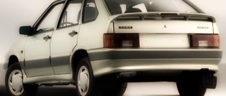
How to improve stock lights
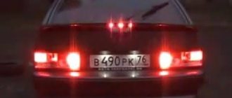
In principle, the rear lights of the VAZ 2112 have optimal lighting characteristics, so there is no need to improve anything particularly. The only thing you can do is improve their appearance somewhat and make them more economical by replacing incandescent lamps with LEDs. The easiest (but not the cheapest) way to change the appearance of the lights is to replace them with more original ones. For example, on the so-called “sticks”.
The rear stick lights look much more presentable than the standard ones
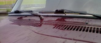
How to remove tail lights and disassemble them
But if we want to start tuning the standard lights, we first need to remove and disassemble them.
Back light
The rear light, which is responsible for the brake light and reverse gear, can be easily removed. Open the trunk door and disconnect the power supply from the lamp.
Removing the power supply from the rear light of a VAZ 2112
Squeeze the clamps and remove the panel with the board and lamps.
Removing the canopy panel
Using a size 8 wrench, unscrew the 2 nuts that secure the device.
Rear light fastening nuts
Loosen 3 nuts securing the decorative reflective trim, and unscrew the fourth one, located closer to the lamp being removed, completely.
Partial dismantling of the decorative trim
Lift the cover and take out the flashlight.
The taillight can now be removed
Corner lantern
Open the trunk door and unscrew the four screws securing the trunk trim closer to the light being removed - two from the bottom, two from the side.
Partial removal of trunk upholstery
We bend the upholstery and see the back of the lamp.
The corner lamp of the VAZ 2112 is located behind the upholstery
Remove the power supply from the device.
Removing the power supply
Using a size 8 socket wrench, unscrew the three nuts securing the light fixture.
These nuts secure the taillight
We push the device back in the direction of travel of the car and remove it from the body.
Removing the corner lamp VAZ 2112
How to disassemble
Unfortunately, the rear lights of the VAZ 2112 are non-separable, so you will have to break them, not disassemble them, but in such a way that they can be repaired later. This can be done in two ways: sawing the body or cutting it with a hot knife. In the first case, it is convenient to use circular attachments on a drill. If you don’t have attachments and don’t want to buy them, you can use a piece of a regular hacksaw blade for metal.
Cutting a lantern with a circular nozzle
To implement the second method, you will need a knife and a gas stove. Heat the knife and cut the lantern around the perimeter. After removing the glass, we clean all melted areas with a file. Barbarism, of course, but it works.
Disassembling the rear light using a hot knife
Assembling the lantern is easier - just connect the halves and fill it with glue, for example, “Moment” or similar. To prevent the lantern from falling apart while the glue dries, you can first grab the parts with a soldering iron at several points.
Assembly of the rear light device VAZ 2112
Where is the reverse sensor located on a VAZ 2110 car?
As already mentioned, this element is installed in the gearbox. This is logical: there is no need to install remote control rods. Why not on the gearshift lever? The sensor must record exactly the moment the gear is engaged, and not the change in the position of the control mechanisms. The exact location is the gearbox housing.
You can only find it while under the car: either in a hole or using a lift. It is screwed into the crankcase in the same way as an oil drain plug: using a threaded connection. The sensor is located horizontally, on the side wall of the gearbox, on the driver's wheel side. A connector and a signal wire are connected to it: there is no other such device in this area.
VAZ-21124 engine control circuit
Connection diagram of the VAZ-21124 engine control system with distributed fuel injection to Euro-2 emission standards (controller M7.9.7): 1 - ignition coils; 2 — nozzles; 3 - controller; 4 - main relay; 5 - fuse connected to the main relay; 6 — cooling system electric fan relay; 7 - fuse connected to the cooling system electric fan relay; 8 - electric fuel pump relay; 9 - fuse connected to the electric fuel pump relay; 10 — mass flow and air temperature sensor; 11 — throttle position sensor; 12 — coolant temperature sensor; 13 — solenoid valve for purge of the adsorber; 14 — oxygen sensor; 15 — knock sensor; 16 — crankshaft position sensor; 17 — idle speed regulator; 18 — immobilizer control unit; 19 — immobilizer status indicator; 20 - phase sensor; 21 — vehicle speed sensor; 22 — electric fuel pump module with fuel level sensor; 23 — oil pressure warning lamp sensor; 24 — coolant temperature indicator sensor; A - block connected to the wiring harness of the ABS cabin group; B — diagnostic block; B - block connected to the air conditioner wiring harness; G - to the “+” terminal of the battery; D — to the side door wiring harness block; E - block connected to the instrument panel wiring harness; G1, G2 - grounding points; I - the order of conditional numbering of plugs in the block of the immobilizer control unit; II - the order of conditional numbering of contacts in the diagnostic block.
Useful: Pinout of diagnostic connector for VAZ cars
Connection diagram of the VAZ-21124 engine control system with distributed fuel injection under Euro-3 toxicity standards (controller M7.9.7): 1 - ignition coils; 2 — nozzles; 3 - controller; 4 - main relay; 5 - fuse connected to the main relay; 6 — cooling system electric fan relay; 7 - fuse connected to the cooling system electric fan relay; 8 - electric fuel pump relay; 9 - fuse connected to the electric fuel pump relay; 10 — mass flow and air temperature sensor; 11 — rough road sensor; 12 — throttle position sensor; 13 — coolant temperature sensor; 14 — idle speed regulator; 15 — control oxygen sensor; 16 — diagnostic oxygen sensor; 17 — solenoid valve for purge of the adsorber; 18 — knock sensor; 19 — crankshaft position sensor; 20 — immobilizer control unit; 21 — immobilizer status indicator; 22 - phase sensor; 23 — vehicle speed sensor; 24 — electric fuel pump module with fuel level sensor; 25 — oil pressure warning lamp sensor; 26 — coolant temperature indicator sensor; A - block connected to the wiring harness of the ABS cabin group; B — diagnostic block; B - block connected to the air conditioner wiring harness; G - to the “+” terminal of the battery; D — to the side door wiring harness block; E - block connected to the instrument panel wiring harness; G1, G2 - grounding points; I - the order of conditional numbering of plugs in the block of the immobilizer control unit; II - the order of conditional numbering of contacts in the diagnostic block.
Why does the reverse gear sensor break?
Any moving mechanical system is designed for a certain number of cycles of use. Therefore, this device has a service life and can break simply due to mechanical aging.
Important: The cause of the reverse lights going out may not be the sensor at all. No one is immune from light bulbs burning out or wiring being broken. The failure may be in the control relay or in the safety unit.
We will look at the reasons relating specifically to the sensor:
- Corrosion of internal contacts due to a leak in the seal and moisture entering the housing. It occurs due to temperature changes and the appearance of deformation gaps.
- Oxidation of connector contacts, up to complete corrosive destruction. The reason is the lack of protective lubricant inside the connector.
- Mechanical destruction of internal parts due to manufacturing defects.
- Fracture or loss of the switching rod from the housing. Occurs in counterfeit products.
- The control rod is jammed into the “on” position. The reason is oil seal wear or internal corrosion.
- Grinding the surface of the slide clamp to the sensor rod.
Symptoms of a malfunctioning reverse sensor
Actually, they boil down to:
- No signal from the sensor. That is, when reverse gear is engaged, lights with known good lamps and wiring do not light up.
- Functional rear parking sensors are not activated.
- The rear view camera does not turn on when the equipment is in working order.
Information: If several devices activated by the reversing sensor suddenly and simultaneously stop working, it is the one that needs to be replaced. Searching for other problems is pointless.
How to change light bulbs
Replacing the bulbs in both lanterns is easy and requires no tools.
Rear center
Open the trunk door and find the rear part of the lamp on it. The board with lamps is secured in it using two plastic clips and at the same time serves as the back cover of the lamp. Squeeze the clamps and remove the board along with the lamps. The power supply does not need to be disconnected.
Removing the panel with light bulbs
Lightly press down the burnt-out light bulb and, turning it counterclockwise, remove it from the socket. In place of the burnt one, install a new one, press and turn clockwise. We snap the board into place.
Back corner
There's not much more fuss here. We open the trunk door and opposite the lamp we find a valve in the upholstery, closed with Velcro. We open it and see the back of the light device.
The corner light is hidden behind a flap in the upholstery
Its back part is fixed with the same plastic latches. We squeeze them and take out the board along with the light bulbs.
Removing the panel with light bulbs
The turn signal lamp is located separately, the parking light and fog light lamps are almost next to each other. We take out the burnt one (press and turn), install a new one (press and turn in the opposite direction).
Replacing light bulbs in the corner rear light fixture of a VAZ 2112
We snap the panel into place and close it with the valve.
Sensor diagnostics
First of all, an external inspection is carried out. We check the integrity of the wiring and the condition of the contact group. It is better to test the wiring with a multimeter from the removed connector to the nearest input into the car's distribution contact box. Next, we test the sensor itself:
- We put the car on a pit or on a lift.
- Disconnect the connector and move it to the side.
- Turn on the ignition without starting the engine.
- We connect the multimeter probes to the sensor and ask an assistant to engage reverse gear.
- A working sensor will show zero resistance between the contacts.
If the test fails, the sensor must be removed from the transmission. In this case, some of the transmission oil will leak out of it, so it is better to prepare a plug in the form of a bolt with the same thread or temporarily screw in another sensor.
Tip: Do not throw away the broken sensor; it may be useful for temporarily closing the hole.
After washing the outside of the housing and cleaning the contacts, you can check the sensor with the same multimeter. The pressing force on the rod is small, provided that it is not blocked by corrosion. Therefore, just press it with your finger and look at the results of measuring the resistance.
We turn on the brake lights forcibly
Relay K1 is successfully replaced with a pad with jumpers. In Fig. 1 just shows its diagram. If there is no such platform, you can temporarily close contacts 4-5. First, check everything mentioned above.
Have an observer watch what happens to the lamps. Press the pedal with one touch and release it. If the lamps do not turn on, check that the fuse is working properly. It's burned out, which means you're looking for a short circuit.
How to and how not to check the “0 Volt” potential
Let’s agree right away that we only work with a voltmeter. Voltage “+12” is caused by connecting one probe to ground. The presence of potential “zero” is checked differently: any of the probes is connected to a terminal with positive voltage, and then the second probe is connected to the wire being tested.
Consider the error: one probe is connected to ground, the second to the terminal being tested, and vol. Here they conclude that there is a “mass” potential, but this is wrong! If the contact with ground is broken, the device will also show “0”. That is, the number “0” does not contain information.
Replacing the sensor
How to choose a new sensor instead of a broken one? In fact, nothing complicated: just don’t buy products from counterfeit manufacturers. Given the availability of packaging technologies, it will not be possible to determine authenticity on your own. Therefore, the only “recipe” is to visit AvtoVAZ brand stores.
When replacing the sensor, you must follow certain steps:
- Before installing a new sensor, you must wait until the gearbox oil drains and clean the threaded hole.
- Be sure to check the sealing washer; without it, oil will leak out of the box.
- After tightening the sensor in the gearbox housing, add oil to the standard level.
- The final touch - before connecting the connector, lubricate the contacts with a special anti-corrosion compound.
Thus, the installation of the sensor will be successful.