According to traffic regulations, it is prohibited to operate a vehicle with a non-functioning sound signal. It serves to prevent emergency situations on the road when road users, for one reason or another, do not see each other. Therefore, a sudden failure of this device can play a cruel joke on the car owner. If such a malfunction is detected, do not put off repairing the horn for a long time. We will tell you about the main reasons for the breakdown, most of which you can handle on your own.
Why are fuses needed?
Fuses are elements of an electrical circuit that protect devices from voltage surges. They consist of a plastic case, two contacts and a working element.
The principle of their operation is simple: each element has an operating voltage, and if this value is exceeded, it will immediately burn out and the circuit will open. In fact, the protective component takes the blow, protecting electrical appliances from damage. Its purchase is much cheaper than replacing one or more consumers, which, among other things, can affect the control of the car.
The cigarette lighter in Lada Vesta has a fuse that blows more often than others. Usually the reason for this is connecting devices with high current consumption or several devices at once through a tee.
Wiring is not ok
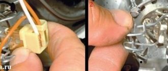
Have you checked all the elements in the chain, but there is still no sound? This means that the problem lies in the car's electrical wiring. At this stage, you will have to stock up on a tester to “check” the circuits. You need to make sure that there is voltage at the signal button, for which you will have to open the steering wheel cover. If your car does not have airbags, then there will be no problems, but if they are present, the task will become much more complicated. Therefore, in such a situation, it is better to contact a car service so as not to accidentally activate the “airbag”.
Share this article with your friends:
Lada Vesta fuse box with description (engine compartment
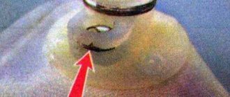
The required box is located above the battery, on the right side of the air filter. On the cover of the unit you can see warning signs in the form of a crossed out figure of a man with a hose and a lightning bolt.
To remove the cover, bend the two latches at the top and bottom. Be careful because... they are very fragile.
Schematic layout
The contents of this mounting block are as follows:
Mounting block
The current limit (amps) is indicated on each component. The Lada Vesta fuse diagram under the hood looks like this:
Lada Vesta fuse diagram
Which circuit each fuse belongs to and which consumer it is responsible for can be found in the table below. Fuse Circuit Chart Fuse Chart Note: Depending on the configuration, some items may not be present.
Table with the designations of the relays that are present in the engine compartment block: Table with the designations of the relays
How to set up bluetooth on Vesta
Let's take a closer look at how to enable bluetooth on Vesta.
The Bluetooth connection algorithm in the Lada Vesta station wagon will be something like this. First of all, turn on the smartphone, find the Bluetooth function in it and switch it to operating mode. The next step is to turn on the car radio. When new equipment is found under the name Vesta, they connect to it. The factory password for Bluetooth from the manufacturer is 0000. After connecting the phone to the MMS for the first time, the password will not be needed in the future.
Lada Vesta fuse box with description (interior)
This mounting block is located in a place familiar to drivers - near the left foot. Actually, the space around the trunk opening button and the headlight adjustment control is the cover of the mounting block.
First, remove the plastic clips (nails) that secure the cover to the upholstery. One of them is located on the side of the ignition switch, the other is in the lower left part of the cover (may be absent on some cars). Next, turn the 3 plastic handles at the bottom and pull the lid, releasing all the holders.
Schematic layout
In the interior mounting block you will see the following picture:
Interior mounting block
In the lower right corner there are spare fuses for the Lada Vesta.
Schematically the block looks like this:
Schematic arrangement of fuses It is deciphered as follows: Explanation of spare fuses Explanation of spare fuses Explanation of spare fuses Explanation of spare fuses Explanation of spare fuses Relays that are present in the cabin: Designations of the relay in the cabin
Body connector
Layout of buttons on the steering wheel
How to install a Volga signal
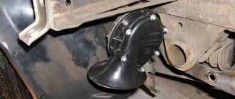
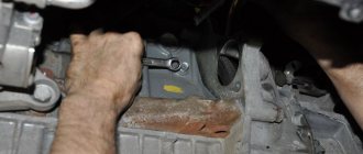
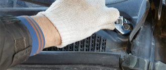
Remove the front bumper (instructions for XRAY, Vesta, Grant, Priora, Kalina, Largus). If it was decided not to remove the standard sound signal (if necessary, you can return to the initial version), then we are looking for a suitable place to install signals from the Volga. Most often they are placed on the front bumper amplifier (on standard mounting bolts), behind the radiator grille or under the headlights on brackets.
Replacing the fuse
In one of the tables, find a device that has stopped working - next to it there will be a designation of a supposedly burnt-out element. At the same time, you will understand where the fuse box is located.
Open the block cover, find and remove the problematic fuse, following the diagrams. The same algorithm applies to a failed relay.
If the contact inside is broken, it means it has burned out. However, this is not always noticeable, so it is better to do a continuity test with a tester.
Before replacing, be sure to find out the cause of the burnout.
The new protective component must match all the characteristics of the old one: the same format, color and current limit designation.
HOW TO CONNECT THE VOLGA SIGNAL
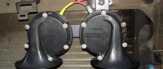
Standard sound signals of LADA cars consume no more than 5A, and Volga horns consume 7A each. In this regard, to connect them it is necessary to use a 4-pin relay. The Volga signal connection diagram is universal for all cars:
Before starting work, it is recommended to disconnect the negative terminal from the battery. All wires are laid in corrugation. We place the relay in a place protected from moisture and dirt. The whole process is also shown in the video:
About the guarantee. If you independently modify the car in terms of electrical components, there is a possibility of refusing warranty service for the car. Therefore, the installation of signals from Volga should be carried out at a service center, where after connection they will be ready to provide a document confirming the quality of work. You can also contact an authorized dealer for such modifications.
Mounting block Lada Vesta in the car interior
The mounting block is located in a familiar place - near the driver’s left foot. To access the relays and fuses:
- turn the plastic handles (3 pieces) holding the unit cover from below;
- remove the lock on the upper right side of the cover;
- Pull the bottom of the cover, disconnect its upper holders to the instrument panel and remove the unit cover.
Fuse diagram (Fuse, Rating, Circuit, Purpose, Fuse type)
- F1 15A K15R Windshield washer mini
- F2 30A *1 /5A *2 K15R Left steering column switch (not luxury/luxury) mini
- F3 10A *1 Left high beam headlight (not luxury) mini
- F4 30A *1 /5A *2 K30S Left steering column switch (not luxury/lux) mini
- F5 15A K15R Heated seats mini
- F6 7.5A *1 K30S Right side lights mini
- F7 10A *1 K30S Left side lights mini
- F8 5A *1 K30S Rear fog lights mini
- F9 3A Direction indicator (turn signals) in the right mini mirror
- F10 5A K15S AMT mini robotic gearbox selector
- F11 10A *1 Left low beam headlight (not luxury) mini
- F12 15A K30S BCM controller (turn signals) mini
- F13 10A K30S BCM controller (own power supply) mini
- F14 10A K30S Mini brake pedal switch off
- F15 5A BTP Power supply for D&O (rain and light sensor), mini headlight range control
- F16 5A BTP Mini brake pedal switch off
- F17 5A BTP Lighting (canopy) for the glove box, trunk, thresholds mini
- F18 3A Direction indicator (turn signals) in the left mini mirror
- F19 10A *1 Right low beam headlight (not luxury) mini
- F20 5A Heated exterior mirrors mini
- F21 15A K15S BU SNPB mini
- F22 5A K15S Gearbox (instrument cluster) mini
- F23 5A K30S Gearbox (instrument cluster) mini
- F24 5A ACC ERA GLONASS, radio mini
- F25 5A VTR Controller ESP9.1 mini
- F26 15A K30S Power supply for mini fuel pump module
- F27 5A K15S Power supply for parking sensors mini
- F28 5A K15S EURU controller (electric power steering) mini
- F29 10A *1 /5A *2 K30S Power supply for mini trailer lighting
- F30 5A K15S Controller ERA GLONASS mini
- F31 5A K30S Controller ERA GLONASS mini
- F32 10A K15S Bus power supply K15M (engine compartment) mini
- F33 5A BTP Window control mini
- F34 5A VTR Power supply for steering angle sensor, mini steering wheel button block
- F35 5A BTP Switch block in the driver's door mini
- F36 15A K30S Radio, mini diagnostic connector
- F37 7.5A K30S Stop lamps right mini
- F38 7.5A K30S Stop lamps left mini
- F39 10A *1 K15R DRL (daytime running lights) not luxury mini
- F40 10A *1 K15R High beam headlight right (not luxury) mini
- F41 20A ACC 12V socket (power supply for additional devices), cigarette lighter JCase
- F42 20A K30S BCM controller (BTP bus power supply) JCase
- F43 20A K30S BCM controller (door locks) JCase
- F44 30A K30S Electric windows (ESP) JCase
- F45 30A K30S Interior heater fan (heater) JCase
- F46 30A *1 K15R Power supply for windshield wipers JCase
- F47 25A *2 K30S EMM controller (PDS, LBS, LGO)
- F48 30A *2 K30S EMM controller (windshield wiper)
- F49 25A *2 K30S EMM controller (PTF, ZPTO, license plate)
- F50 25A *1 K30S EMM controller (LDS, PBS, PGO)
Fuse box Lada Vesta in the engine compartment
Fuse diagram:
| Fuse number (current, A) | Fuse color | Protected electrical circuit |
| F60 (70 A) | Pink | Electric power steering (EPS) |
| F61 (30 A) | Green | Rear window defroster |
| F62 (40 A) | Orange | Stability Program (ESP) Controller |
| F63 (15 A) | Blue | Air conditioner |
| F64 (5 A) | Light brown | Not used |
| F65 (25 A) | White | Stability Program (ESP) Controller |
| F66 (5 A) | Light brown | Automatic transmission (AMT) |
| F67 (-) | – | Not used |
| F68 (70 A) | Pink | Automatic transmission (AMT) |
| F69 (15 A) | Blue | Air conditioner |
| F70 (60 A) | Blue | Power supply circuits for fuses F4, 6, 7, 8, 12, 13, 14, 23, 26, 29, 31, 36, 37, 38, 42, 43, 44, 45, 47, 48, 49, 50 of the mounting block in the passenger compartment |
| F71 (60 A) | Blue | Generator |
| F72 (60 A) | Blue | |
| F73 (10 A) | Red | Sound signal |
| F74 (5 A) | Light brown | Reversing light switch |
| F75 (60 A) | Blue | Heated windshield |
| F76 (10 A) | Red | Anti-theft alarm |
| F77 (-) | – | Not used |
| F78 (7.5 A) | Brown | Canister purge valves, engine management system sensors (oxygen sensors, timing valve) |
| F79 (40 A) | Orange | Engine cooling fan |
| F80 (5 A) | Light brown | Heated windshield |
| F81 (-) | Blue | Not used |
| F82 (-) | Blue | Not used |
Addition from car owners
More information about fuses and relays is provided by unnown:
In Table 1, the data of the original relays is highlighted in color. I tried to collect the main characteristics (min required) of possible relay analogues, similar in size, design and characteristics. Where there are empty cells in the table, there is no data. Equivalent R is the actual measurement from the relay contacts. Of course, my data is not a panacea for all ills. Data collected from manufacturers' sources (data sheet) and from online store catalogs.
Before replacing a fuse, you must first determine the cause of its blown. The manufacturer does not allow the use of fuses that differ in current rating from those recommended in the tables below. This can lead to malfunctions in the operation of Vesta's electrical equipment, short circuits and even a car fire!
Attention!
The relay and fuse diagram may differ depending on the configuration and production date of the vehicle. Current diagrams of the mounting block are presented in the operating manual for the date of manufacture of the vehicle (download the manual).
Let us remind you that you can quickly find the necessary material through the contents of Lada Vesta.
Key words: Lada Vesta mounting block
How to connect the Volga signal
Standard sound signals of LADA cars consume no more than 5A, and Volga horns consume 7A each. In this regard, to connect them it is necessary to use a 4-pin relay. The Volga signal connection diagram is universal for all cars:
Before starting work, it is recommended to disconnect the negative terminal from the battery. All wires are laid in corrugation. We place the relay in a place protected from moisture and dirt. The whole process is also shown in the video:
About the guarantee. If you independently modify the car in terms of electrical components, there is a possibility of refusing warranty service for the car. Therefore, the installation of signals from Volga should be carried out at a service center, where after connection they will be ready to provide a document confirming the quality of work. You can also contact an authorized dealer for such modifications.
Are you satisfied with the operation of the standard sound signal on the LADA model? Are you ready to install a Volga horn? Let us remind you that we previously looked at other methods that can make operating a car more comfortable. For example, installing a gas tank cap bracket or how to make a flip-flop ignition key.
Keywords: lada xray safety | safety of Lada Vesta | safety of Lada Largus | safety of Lada Granta | safety of Lada Kalina | safety of Lada Priora | 4x4 safety | Niva safety | universal article
Found an error? Select it and press Ctrl+Enter..
- AvtoVAZ spoke about plans for drones and electric cars
- Lada Vesta spare parts, who is the manufacturer?
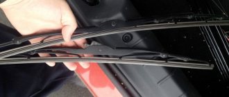
- If the rear wiper of the Lada Kalina 2 does not clean well (the reason is the leash, not the brush)
- Installation of side protective pads on the Lada Vesta frill