02/04/2022 7,682 VAZ Kalina
Author: Ivan Baranov
Auto manufacturers today use many technological solutions to ensure more comfortable driving. One of such devices is CBKE. What is the central unit of body electronics Kalina 2 needed for, what functions does it perform and what malfunctions are typical for it - read in this article.
[Hide]
TsBKE Lada Granta, Kalina, Priora: purpose, articles, pinout, errors
The central body electronics unit (CBEC) is designed to perform a number of vehicle functions. There are about 15 varieties of this block in total. We understand the features of the CBKE, study the connectors, the purpose of the contacts, fault codes, etc.
Turbomotor412 helped the Lada.Online website in collecting information.
Replacing TsBKE Kalina 2 — DRIVE2
A common problem occurred among new VAZs produced in 2013-2014. At one point, when turning on the turn signal, the turn signal stuck (that is, all attempts to play tricks with it by turning it on/off led to nothing). The reason is a stuck CBKE key (apparently the keys were selected without a reserve for consumer power). Because Due to some circumstances, the car is no longer under warranty, so I had to figure it out myself, below are brief instructions: 1. To make sure that the reason was in the TsKBE, I pulled the fuses (I think it’s no secret to anyone where the fuse block is located). Having disconnected the TsBKE 30A fuse, the turn signal immediately went off, which gives 99% confidence that the problem lies there. 2. I bought a new TsBKE unit, the only place where I was able to find it was the navigator74 store (not an advertisement, it was just a real problem for me to find a spare part). There are 4 modifications of TsBKE, all produced by ITELMA, the only difference is in the last number of the custom code (10-Kalina and Granta not luxury; 20-Kalina and Granta Lux; 11 - new Priora not luxury; 21 - new Priora luxury; - I’ll misfire, this not the ultimate truth, on my luxury cabin there was exactly 20, in any case, it’s better to remove it first and then buy a new one. 3. By the location of the block, I’ll tell you right away, it was placed there by a designer who hates people. Because there’s no photo I did, I’ll just write - the block is located on the left, behind the fuse panel. A slide is used to fasten it, it is fixed on this slide with a bolt and nut. You can feel it if you reach into that area with your hand through the opening from below, it is the only plastic device in that area 4. Regarding dismantling, someone wrote that it is necessary to completely remove the dashboard, instrument panel, etc., of course this is possible, but the quicker next step is to remove the fuse box cover, unscrew and remove the low beam switch (through the hole that will remain from switch, if desired, you can see the same bolt that is attached to the TsBKE on the slide. For convenience, you can also unscrew the 3 lower torpedo mounting bolts. 5. Next is the most interesting thing - first of all you need to loosen that same bolt. I took a large screwdriver and rotated it at an angle (which is very inconvenient) and loosened the bolt. Next, with one hand, pushing it from below from the side of the pedals, 2 will not fit there, and finally unscrew the nut. 6. I removed the connectors (there are 2 of them at the end, and 2 of the same ones on the inside). You don’t have to worry about getting confused - they correspond to the colors of the sockets (black and gray, respectively) 7. Pulling the released module a little to the left, I removed the module from the slide and, with the help of that mother, pulled it out again through the bottom, where the pedals to the light 8. Then everything is in reverse order , only the cable connections must be made before installing the unit in the slide, it’s easier this way. By the way, I did not tighten the fastening screw too much. PY SY, before starting work, be sure to remove the terminals from the battery. And may the force be with you
Purpose of CBKE
The TsBKE block is designed to perform the following functions
:
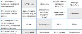
- alarm system;
- control of the windshield wiper in the “manual control” mode;
- control of the windshield wiper in the “automatic control” mode (for TsBKE 21900-3840080-20);
- windshield defroster control;
- control of the rear window heater and electric side mirror heaters;
- control of low beam headlights, side lights and daytime running lights in the “manual control” mode, provided for by UNECE Regulation No. 48-04;
- control of low beam headlights, side lights, daytime running lights in the “automatic control” mode (for TsBKE 21900-3840080-20);
- control of daytime running lights in accordance with UNECE Regulation No. 48-04;
- high beam headlight control;
- control of direction indicator and hazard warning lamps;
- interior lamp control;
- energy saving control of vehicle interior lighting devices;
- central locking: locking/unlocking the side door locks from the key, from the driver's door lock button from the passenger compartment, from the button in the driver's door module;
- opening the trunk lid (tailgate) from a button in the cabin;
- control of electric window lifters;
- remote control;
- control of electric drives of side mirrors (for TsBKE 21900-3840080-20);
- front seat heating control;
- indication;
- trunk lighting control (for TsBKE 21900-3840080-20)
Granta and Starline - all options
0 people signed up. Next goal: 100
From the very beginning of sales of the new Lada Granta family, owners began to experience inconvenience when using the central locking (CL). The fact is that in some car versions, when the engine is running, the central lock only closes the driver's door. Closing all doors is only possible when the ignition is turned off. This algorithm for the operation of the central lock complicates life for owners when installing an additional car alarm with auto start.
Here's what Lada Granta FL owners write in one of the VK groups:
The new FL grant has a strange locking mechanism. 1. if you lower the driver's flag when the car is turned off, then all the others will lower and close, everything is fine. 2. If the engine is running, then when the driver's flag is lowered, the rest remain open. Well, God bless him, maybe the thieves won’t get caught in the traffic jam. BUT! When you arm the car with a manual transmission and get out of the car, the engine naturally runs before arming...you arm it and...since the engine is running, one driver's flag goes down. Three passenger doors remain open. Pressing the close button again does nothing. You have to disarm and re-arm, and this already resets the autorun. Indeed, such an algorithm for the operation of the central locking is indicated in the car’s operating manual:
Central locking and unlocking of side doors from the passenger compartment (in a variant). To lock the side door locks from inside the vehicle, press the lock button into the driver's door or (in the optional version) press the lock button in the driver's door module. In versions with a driver's door module, locking the side doors using the button in the driver's door is only possible when the ignition is turned off. At the moment, this information has already been conveyed to AvtoVAZ. It remains to be hoped that this feature of the central locking system will be corrected in the near future.
Finally got around to installing a new power window switch assembly. I started by inserting a new block from Kalina 2 in place of the original one. Using plastic spatulas to remove the trim, I removed the Granta power window switch block.
On the website where I ordered the block (see part 1), there is a template for marking.
I removed the original block and marked the casing for the new one.
I cut out the seat with a utility knife.
Installed a new block.
The next step was to remove the casing and conduct +12V, which I took from the fuse of the factory central locking unit (it seemed logical to me
Classification of CBKE
Types of CBKE, features and their interchangeability
:
- 21900-3840080-20 Priora 2, Granta, Kalina 2 (in luxury trim levels), Datsun Ondo (Dream 1-2)
- 21900-3840080-10 Priora 2, Granta, Kalina 2 (in standard configurations)
- 21900-3840080-11 Priora 2 in the Standard configuration. Until 2016, Priora 2 was installed in the standard configuration
- 21900-3840080-21 Priora 2 in the Lux configuration early (2014-2015), not installed on the Norma, but will fit
- 21900-3840080-15 Priora 2 in Standard configuration, Kalina 2, Granta in Comfort configuration
- 21900-3840080-30 Datsun Mido in the Trust 1-3 configuration until 2015
- 21900-3840080-40 Datsun Mido in Dream 1, Dream 2 trim levels until 2015
- 21900-3840080-50 new block to replace 21900-3840080-10 (does not burn out)
- 21900-3840080-60 new block to replace 21900-3840080-20 (does not burn out)
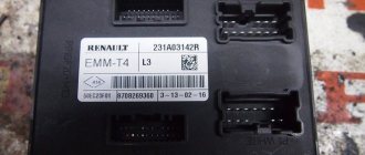
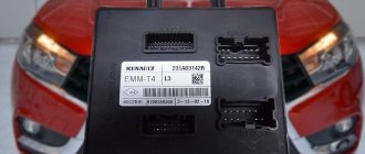
- 8450100527 Grant from 2022
- 8450100534 Kalina 2 from 2022
- 8450100535 Datsun Ondo from 2022
- 8450100536 Datsun Mido from 2022 (Trust 1-3, Dream 1-2)
- 8450101126 Granta FL in the Classic, Optima and Comfort trim levels exclusively in cars with AMT (to implement the creeping AMT 2.0 mode, a door open signal is needed in the CAN bus, so it was necessary to introduce TsBKE)
- 8450101145 Granta FL in Luxe package
Buy
The TsBKE block is available in our online store (ask about availability in the comments).
The first disappointment from a car or CBKE - Lada Kalina Hatchback, 1.6 l., 2013 on DRIVE2
I'll decipher part of the title - TsBKE - central unit of body electronics. Servicemen will understand you if you say comfort module (unit), electronics control unit, etc. But officially this hellish school (at the moment) of AvtoVAZ is called exactly that - TsBKE. More details about CBKE, if anyone is interested
This TsBKE was developed with the goal, attention, to reduce the number of failures of body electronics. The idea is sound and correct, but it needs to be implemented in the same way as it was invented. In the meantime, judging by the number of complaints and my conversations with warranty engineers, this unit is one big failure. That is, if earlier on Kalina 1 your turn signal failed, for example, you drove with grief to the store (car market), bought a cheap relay (fuse) and drove on, but now your turn signal simply “sticks” in on position. And nothing can be done about it. The only way is to remove the battery terminal. Only then will these lights go out. You cannot drive according to traffic rules with such a malfunction. The emergency light doesn't work. Added to all this is the lack of high beam headlights. As you probably understood from the introduction, this exact misfortune happened to me. The left turn signal signaled a constant desire to go left. Visiting or calling all ODs in the city of Perm did not bring any results. No, of course I brought it - yes, TsBKE, yes, warranty, no questions asked, no, no spare parts available, wait - from 2 weeks to a month. And the first thought - here I am... And what I found out is that the problem is massive
. A friend suddenly remembered that during his last visit to the OD, he heard how one of the Kalinas had been waiting for its spare part for 2 weeks. One OD advised me to unscrew the light bulbs and show the left turn with my hand from the window) Perm residents and those who know the Perm spring weather, I think, will only grin at such a proposal. In the evening, I would probably have to hang a bunch of flickers on my hand so that they would see it) And yes, the normal option is to open the window, stick out your hand, and a piece of liquid Russian straw lands in your face, safety is at its best. Well, the cleanliness of the above-mentioned person, as well as the interior of the car. I would like to separately write my gratitude to the employees of the Ex-Auto OD with whom I communicated, who understood the situation and did everything in their power to resolve the issue. As a result, I managed to solve the problem within a week. This week I tried to limit my travel by car, I drove only when necessary, I drove extremely prudently and predictably for other participants in the road trip. To all owners of Grant, Kalin2 and new restyled Prior (yes, you also have this ill-fated block) - rely on your local OD. That they will order the necessary spare parts in advance and you will not have to lay your car down for at least 2 weeks. But, again, as I understand from communicating with OD, it is not their particular fault that the spare parts are not in stock; the manufacturer, the well-known Itelma, is not coping with it. But AvtoVAZ wants to say a lot of unpleasant things. There has been a wave of problems with TsBKE since last year, it all started with Grant, then moved to Kalina, I wonder what will happen to Priora. There were no mass recalls of problematic cars (probably they didn’t even understand which cars were problematic or simply didn’t find out). In more than six months, it was possible to try to reduce the amount of inconvenience caused to owners and conscientious buyers. Nevermind. Replacing the block took about 1.5 hours. True, after replacing, under the rug I found this:
Tell me, who knows where it might be from and whether it’s worth looking for this place. Is this spare part critical in general?
Result:
TsBKE connectors
- XP1 connector - Molex 34729-0080
- XP2 connector - Molex 31372-1000
- connector X3 - Molex 34729-0200
- connector X4 - Molex 31372-1100
TsBKE pinout
The location of the TsBKE contact connectors is shown in the figure:
- Enter exit. CAN bus (L – line)
- Enter exit. CAN bus (H – line)
- Enter exit. Rear window heating control
- Exit. Heated windshield relay
- Entrance. Hazard switch
- Entrance. Trunk lock actuator switch
- Entrance. Windshield Wiper Switch (Intermittent Position)
- Entrance. Windshield Wiper Switch (Low Speed Position)
- Entrance. Windshield Wiper Switch (High Speed Position)
- Entrance. Windshield washer
- Exit. Seat heating relay
- Exit. Heated windshield switch
- Enter exit. Lighting control module (Automatic lighting mode) – for 21900-3840080-20 Not activated – for 21900-3840080-10
- Terminal 15
- Entrance. Engine compartment lamp switch
- Entrance. Light switch (Left side direction indicators)
- Entrance. Light switch (Starboard direction indicators)
- Enter exit. Headlight high beam relay control
- Exit. Low beam relay
- Entrance. Lighting control module (Low beam mode)
- Exit. Alarm sound
- Exit. Windshield Wiper Motor (Low Speed Mode)
- Terminal 30 (Turn signals, daytime running lights, low current signals)
- Exit. Turn indicators "Left side"
- Exit. Direction indicators "Right side"
- Exit. Daytime Running Lights
- Enter exit. Park position windshield wiper
- Exit. Windshield Wiper Motor (High Speed Mode)
- Terminal 30 (Windshield wiper motor, interior lighting)
- Terminal 30 (Power windows, door and trunk locks)
- Exit. Trunk lighting – for 21900-3840080-20 Not activated – for 21900-3840080-10
- Exit. Power window switch power supply
- Entrance. Rear left door power window switch - for 21900-3840080-20 Not activated - for 21900-3840080-10
- Entrance. Rear right door power window switch - for 21900-3840080-20 Not activated - for 21900-3840080-10
- Entrance. Front right door power window switch
- Exit. Electrically controlled mirror right (Mode “Up / Down”) – for 21900-3840080-20 Not activated – for 21900-3840080-10
- Exit. Electrically controlled mirror right (Mode “Right / Left”) – for 21900-3840080-20 Not activated – for 21900-3840080-10
- Enter exit. LIN bus
- Housing (Low Current Loads)
- Exit. Trunk lock drive
- Exit. Interior lighting unit
- Entrance. Airbag activation signal
- Entrance. Rain sensor sensitivity regulator – for 21900-3840080-20 Not activated – for 21900-3840080-10
- Entrance. Trunk light switch
- Enter exit. CAN bus (L – line)
- Enter exit. CAN bus (H – line)
- Entrance. Front right door switch
- Entrance. Rear passenger door switch
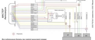
- Autostart (for Lada Connect system)
- Entrance. Front left door switch
- Exit. Car interior lighting (Energy saving mode)
- Exit. Driver's door lock motor
- Exit. Front left door power window
- Exit. Front right door power window
- Exit. Rear left door power window – for 21900-3840080-20 Not activated – for 21900-3840080-10
- Exit. Rear right door power window – for 21900-3840080-20 Not activated – for 21900-3840080-10
- Housing (High Current Loads)
- Exit. Passenger door lock motors
- Exit. General "starboard"
- Exit. General "left side"
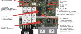
Main block
The main block with fuses and relays is located under the instrument panel on the driver's side, behind the protective cover.
Scheme Option 1
Scheme Option 2
Description of fuses
p, blockquote 10,0,0,0,0 —>
| F1 | 15A Electronic engine control unit, cooling fan relay, fuel injectors |
| F2 | 30A Electric windows |
| F3 | 15A Hazard alarm |
| F4 | 20A Windshield wiper, airbag |
| F5 | 25A Heater (viburnum heater fuse), Electric power steering control unit, Windshield washer |
| F6 | 20A Horn |
| F7 | 10A LCD instrument cluster indicator, Brake light switch and lamps, Interior lighting |
| F8 | 20A Heated rear window |
| F9 | 5A Side light bulbs on the right side, Glove box light bulb |
| F10 | 5A Side light bulbs on the left side, Outside lighting indicator in the instrument cluster, License plate light bulbs |
| F11 | 7.55A Rear fog light, Immobilizer control unit |
| F12 | 7.5A Low beam lamp right block - headlights |
| F13 | 7.5A Low beam lamp left block - headlights |
| F14 | 10A High beam lamp right block - headlights |
| F15 | 10A High beam lamp left block - headlights |
| F16 | 10A Right fog lamp |
| F17 | 10A Left fog lamp |
| F18 | 20A Heated front seats, cigarette lighter |
| F19 | 10A ABS |
| F20 | 15A Cigarette lighter , luggage compartment lock, diagnostic connector |
| F21 | 10A Transmission reverse lock circuit |
| F22 | 15A Security alarm control unit |
| F23 | 10A Electric power steering control unit |
| F24 | 7.5A Air conditioner |
| F25 | 10A Interior lighting, brake lights |
| F26 | 25A ABS |
| F27 | Spare |
| F28 | Spare |
| F29 | Spare |
| F30 | Spare |
| F31 | 50A Electric power steering |
| F32 | 30A ABS |
Fuse number 20 at 15A is responsible for the cigarette lighter.
Relay purpose
p, blockquote 12,1,0,0,0 —>
| K1 | Headlight washer relay |
| K2 | Power window relay |
| K3 | Additional starter relay |
| K4 | Ignition switch unloading relay |
| K5 | Alarm relay |
| K6 | Heated Seat Relay / Wiper Relay |
| K7 | High beam relay |
| K8 | Horn relay |
| K9 | Fog light relay |
| K10 | Relay for heated rear window and exterior mirrors |
| K11 | Seat heating relay |
| K12 | Fuel pump relay |
| K13 | Reverse light relay |
| K14 | Radiator cooling fan relay |
| K15 | Heated windshield relay |
| K16 | Heated windshield relay |
| K17 | A/C compressor clutch relay |
CBKE errors
- * there is no fault code in TsBKE 21900-3840080-10;
- If an “active” fault code is detected, perform the checks outlined in the “diagnostics” column;
- After troubleshooting, clear fault codes using a diagnostic tool.
Advice
: To read errors in electronic units, car owners often use the ELM327 adapter (buy on Ali) and the OpenDiagPro program (the mobile version of OpenDiag does not support working with TsBKE)
Deciphering fault codes
:
- B1002 Open in driver lock control circuit
- B1004 Open in the front left window control circuit
- B1006 * Open in the rear left window control circuit
- B1008 Open in the alarm sound control circuit
- B1010 Open in the trunk gear motor control circuit
- B1012 Open in the passenger lock control circuit
- B1014 Open in the front right power window control circuit
- B1016 * Open in the rear right window control circuit
- B1017 ROM checksum error of the central unit of body electronics
- B1018 Short circuit in the rear window heating relay coil circuit
- B1019 Short circuit in the windshield heating relay coil circuit
- B1020 Short circuit in the seat heater relay coil circuit
- B1021 Wiper malfunction
- B1023 Short to ground or overheating in the control circuit of the common board bus
- B1027 Malfunction of the power window control keys in the passenger doors
- B1028 * Short to ground in the rain sensor sensitivity regulator circuit
- B1030 Open circuit (lamp burnout) of daytime running lights
- B1031 * Open circuit in the rain sensor sensitivity regulator circuit
- B1033 Open (lamp burnout) in the left turn signal circuit
- B1034 Open (lamp burnout) in the right turn signal circuit
- B1040 Open or short to ground in the low beam headlight relay coil circuit
- B1041 * Short circuit in the automatic lighting control relay coil circuit
- B1042 Short circuit in the high beam relay coil circuit
- B1043 Short circuit in the low beam relay coil circuit
- U1044 Lack of communication with MDV
- U1045 Communication error with MDV
- U1046 * Communication error with rain and light sensor
- U1047 * No communication with rain and light sensor
- U1048 CAN bus fault
- B1049 High voltage on-board network
- B1050 Low voltage on-board network
- B1051 * Short to ground in the right mirror control circuit
- B1052 * Left Mirror Control Circuit Malfunction
- B1057 Internal malfunction of the MDV
Steps from “Norma” to “Lux”. Part 1. — Lada Kalina Sedan, 1.6 l., 2006 on DRIVE2
Good day, FRIENDS.
It all started when I broke the passenger rear view mirror. And since I never liked them, this is an excellent reason for Tuning))
I chose mirrors from Granta Liftback, with electric drive, heating, and collars.
Mirrors.
To connect the electric drive I decided to use the ESP control unit from Kalina Lux
ESP control unit
I know that there are extra hemorrhoids, and that it could have been done simpler. BUT! I want to do everything well, as close to standard as possible! Well, rear windows are planned in the near future! But as it turned out, this block communicates with the comfort block via one wire, which is not supported by the comfort block from Norma. I decided to replace the standard block with a block from Lux. They have different connectors, which means you will have to redistribute the contacts. After reading the Internet I found these diagrams.
Comfort Block Diagram Standards
Full size
Luxury Comfort Block Diagram
XP1 1st - ? — New — To the ESP engine of the front-right door. 2nd - ? — New — +/- on all doors. 3rd - Yellow - from pin 14 - To the motors for closing all doors (to all doors). 4th - Orange-Black - New - to the ESP engine of the rear-right door. - No need for a while. 5th - Red-Blue - from the 17th contact - opening the passenger doors. 6th - Black - from the 6th contact - To Ground. 7th - ? — New — to the ESP engine of the rear-left door. - No need for a while. 8th - Blue - from pin 24 - Control of starboard turn signals. 9th - Red - from pin 23 - to terminal 30 (+12V?) 10th - Reserved 11th - ? — New — +/- in the driver’s and rear left door and trunk. 12th - Black - wire from pin 6 - To Ground. 13th - Green-black - New - connect the ESP of the front-left door to the engine. 14th - Blue-Black - from the 16th contact - Control of the left side turn signals. 15th - Red - from pin 23 - to terminal 30 (+12V?)
XP2 1st - Pink-Red - from pin 19 - to the trunk opening motor. 2nd - Reserve 3rd - ? — New — To the power window button of the Rear-Right door. - No need for a while. 4th - White-Black - from pin 25 - Trunk opening limit switch. 5th - ? — New — Passenger mirror up and down. 6th - Red-black - from pin 18 - Opening the driver's door. 7th - Brown-Red - from the 11th contact - Front right door limit switch. 8th - ? — New — Illuminated power window buttons. 9th - ? — New — Passenger mirror left and right. 10th - Red-Blue - from the 15th contact - K-Lin bus. 11th - ? — New — ESP button for the front-right door. 12th - ? — New — ESP button for the rear-left door. - No need for a while. 13th - Gray - from the 5th contact - Heated rear window. 14th - Reserve 15th - Reserve 16th - White-Red - from the 10th contact - Opening the rear doors. 17th - Reserve 18th - Black and White - from the 9th contact - Opening the hood. 19th - Reserve 20th - to the siren - No need.
XP3 - Not used
Attention Questions: - Has anyone ever engaged in such masturbation? Or am I the first to decide on this? — In the diagrams there is a reference to Terminal 30, does anyone know what kind of terminal this is? I'm guessing it's a constant +12V, am I right? — The normal unit is connected to terminal 71 of the ECM/terminal 18 of the APS, but the Lux unit does not seem to be connected to the controller at all, or am I missing something? — The normal unit was connected to the instrument cluster (Terminal 8), but the Lux unit is not connected to the combination at all, do I need to connect it and where? — The standard unit has an output for the rear window heating relay, but the luxury unit does not, will it work? Or how is control implemented in Lux? — If anyone can help with the color palette in the lux connector, I would be grateful.
Characteristics of the Kalina electrical package control unit
The Kalina electrical package control unit is used to automatically raise and lower windows and control doors. Additionally, it makes it possible to control alarm activation and trunk opening.
If we are talking about the luxury configuration of Kalina 2, then the electrical package control unit is responsible for blocking the ignition switch. That is why any malfunctions in its operation negatively affect the driving performance of the vehicle.
Electronic unit under the rear seat of the Lada Kalina: what is it called and what is it responsible for?
I am glad to welcome you to my channel, and today we will talk about one of the very interesting blocks of the Lada Kalina car, which is located under the rear seat, and is also hidden under the carpet approximately in the place where I marked in the photo below:
If you have never heard of this unit before, and have not seen that you have it, you can check by pulling back the carpet and you will see the following picture:
As you can see, it is protected by a metal bar for obvious reasons, so that your passengers do not crush it with their butt.
So why is it needed in a car and what function does it perform? If you look at official websites or catalogues, its name may be as follows: electrical package control unit. Among car enthusiasts, this “box” is most often called a comfort block. So what devices is this part responsible for? Let's list some of them:
- standard security system
- interior lighting
- door locking
- window control
- glass heating
- mirror control
- climate system
This is not a complete list, and depending on the configuration, it may differ. But as you already understood, the failure of this unit can literally paralyze the operation of your Kalina’s electronics. Very often, owners begin their search exactly where they see the problem: that is, in simple words, the window regulator has failed - they change its motor to a new one, although often the problem lies precisely in this comfort unit.
It may even get to the point where the car simply refuses to start, and again the cause of this may be a malfunction of this unit. So, if you are the happy owner of this “berry”, keep in mind that there is such a part that is responsible for many instruments and devices.
If the information was useful, do not forget to give it a thumbs up, and to receive even more new and interesting notes, subscribe to the channel. Thank you for your attention.
Source
Personalize existing features
The manufacturer has provided for the timing of regular technical inspections, which are mandatory. For non-compliance, the company reserves the opportunity to deprive the car owner of the right to free service.
The most vulnerable is the comfort block, which includes many logical circuits. Its purpose boils down to the following functions:
- activation of interior lighting;
- adjusting the operation of car alarms;
- turning on the heated rear window;
- automatic mirror adjustment;
- control of electric windows;
- remote control of locks.
The manufacturer has provided the ability to personalize each element. To do this, the electrical package control unit must be recoded at an authorized automotive center. Using official software, the wizard will add or remove certain features. If everything is done correctly, 20 minutes after requesting the appropriate service, you can safely use the “iron horse”.
According to reviews from car enthusiasts, the Lada Kalina car is distinguished by electronic filling with increased sensitivity to operating conditions. Aggressive driving style and minor damage lead to malfunctions.
As a result, you need to visit a service station to replace the device. To do this, remove the control unit, which must be done as follows:
- turn off the battery;
- unscrew the screws from the driver's seat;
- Use a ratchet wrench to remove the nut;
- the plastic plug is squeezed out completely;
- carefully pull out the seat;
- remove the seat by dismantling the terminals;
- remove the cover plate.
The replacement procedure on the Kalina 2 model is completed by folding the carpet and installing a new block. After this, all procedures are carried out in reverse order.
Gearbox lever rattling
For LADA Kalina, a typical malfunction is rattling in the area of the gearshift lever, which mainly becomes noticeable when the engine is running at speeds of about 3000. The source of the side sound is the bushing, which is made a little thicker than necessary, and because of this, a gap appears in the mount. To resolve this problem you need to do the following:
- remove the handle cover, which is attached with latches;
- using two 13mm wrenches, unscrew the nut and bolt;
- remove washers and bushings;
- to eliminate rattling, the bushing in the middle needs to be slightly sharpened in width or the mount should be lubricated with sealant;
- Having done this, mount everything back. The sealant does not help out every time, but if you sharpen the bushing by 0.3 mm, the result is guaranteed.
It’s safe to say that repairing a Lada Kalina car yourself is not so scary. Every car enthusiast has the opportunity to eliminate minor malfunctions of this car. You just need to believe in yourself, follow our advice and everything will work out!
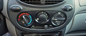
Non-specific types of services
Even if the rules for safe operation of the vehicle are observed, the heater control unit may require servicing or replacement. This happens as a result of sudden switching of the heating knob of the Lada Kalina car. The operating instructions indicate that you must wait until the system warms up to a minimum, otherwise expensive repairs will be required.
From a financial point of view, the stove control unit will not be cheap, so its careful operation will save the family budget.
The heater control unit cannot be replaced independently due to the need to use special equipment. Much less often problems arise at the level of the engine control system.
The need to visit a service station will be caused by driving on a gravel road, an accident, or the result of unprofessional maintenance. The engine management system is responsible for fuel injection, so any deviations in its operation immediately put the car on hold. How long it will take to replace the engine control unit will be decided by the technician after an inspection.
It is cheaper, but repairs take much longer when the body electronics unit comes under attack. The problem can only be diagnosed in a service center. The duration is due to the fact that if the engine control unit can be replaced as a single whole, then part of the wiring must be changed along with the electronics.
Voltage surges or a simple short circuit can damage a certain sector. The light control unit will be the first to tell you about this.
Incorrectly working turn signals or emergency lights are the first sign indicating a failure in the electronic component of the car. There is no point in delaying a visit to the service center. Otherwise, the ESP unit responsible for dynamic stabilization will come under attack. Even with minor problems, the driver will notice a decrease in the lateral dynamics of the vehicle.
Lada Kalina requires regular maintenance as prescribed by the manufacturer. If the specified deadlines are met, each element of the system will work properly.
Replacement instructions
First you need to remove the instrument panel on the center console, then remove the lower part of the dashboard trim under the steering wheel. Now you need to unscrew the fuse box and turn it so that it takes a horizontal position. You need to stick your hand into the freed space until it comes into contact with the shelf on which the TsBKE is installed.
By unscrewing the fixing bolt, you can pull up the control unit and, after disconnecting the two electrical connectors, carefully pull it out. After dismantling the device, it is repaired or replaced with a new one. Installation of the device is carried out strictly in reverse order.
The introduction of modern technologies in the field of control of electronic equipment of a car makes the driver’s work easier, frees him from unnecessary loads and reduces the likelihood of road accidents. Along with the positive aspects of the implementation of CBKE, there are also a number of disadvantages associated with the unreliability of some nodes. Factory engineers are working hard on this problem. According to recent reviews from car enthusiasts, the number of malfunctions of the central unit of body electronics and the frequency of their occurrence are decreasing.
The electrical package control unit (pictured below) Kalina Lux does not work. Or rather, it does not respond to my presses. It is illuminated, when I press the buttons, click, I hear a single short sound in the area of the speedometer/heater (you can hear it in the video below). This thing appeared in the morning, I walked away for an hour, everything worked. By evening everything stopped responding again and it’s been like this for the whole day. Neither the central locking, nor the mirrors, nor the power windows respond to my presses.. What's the matter? I disconnected the terminal for 15 minutes, it didn’t help, the alarm was starline.
Megapolis-Auto provides warranty and post-warranty support for professional anti-theft and security systems and AlarmTrade.
The company was awarded the status of "Industry Leader 2014"
New articles in the section
Using a polarized relay in a car.
Material from Maxim from the site: https://www.drive2.ru So, another useful modification of minimal complexity. With frequent and not very long trips during the day, you have to turn off the dimensions and the radio every time you get out of the car, and when you return, turn everything back on. So I thought about it
Checking the range of the Pandora DX 90B communication channel
One of the clients complained about poor communication, or rather about the short control distance and periodic loss of communication, that is, the key fob “complains” about the lack of communication (in this case it plays the melody of the lack of communication) And we had a great opportunity to deal with the problem of range,
Stealing a Lada Vesta with a magnet. How to protect yourself?
Many times in conversations with clients we discussed the issue of unlocking standard ignition locks using modern powerful magnets. And, frankly, few people believed that this was possible in principle. provided us with and also posted a video online demonstrating this method of opening
Double-glazed window control unit “Norma” 1118 – 6512010 for VAZ 11183 “Kalina”
©Aktuator On cars of the Kalina family, 2 types of non-interchangeable (by wiring) glass control controller 1118 - 6512010 and 11180 - 3763040 can be installed. 1118 – 6512010 has one 25-pin connection connector, 1118 – 3763040 (1118 – 3763040 – 10) – two connectors.
Remote control system for double-glazed windows “norm” on a VAZ 11183, Kalina. Controls power windows and central door locking. When the connector is removed, the engine does not start; the device performs some of the anti-theft functions.
Connection
| Sign | Malfunction | Possible reasons | Diagnostics | Elimination method |
| 1 beep IC flashes | The key code is not readable |
| № | Wire color | Purpose, addressing |
| 1 | External shock or volume sensor input (Not used)* | |
| 2 | Pink/Black | To the door lock switch in the switch block |
| 3 | Brown/Green | K-Line. To Kl. 71 ECM, Cl. 18 APS‑6 |
| 4 | Brown | Connects to ground when the driver's door is closed |
| 5 | Grey | To rear window heating element |
| 6 | Black | Weight |
| 7 | Pink/White | To the door lock switch in the switch block |
| 8 | Yellow/Blue | In the instrument cluster, to the APS-6 indicator |
| 9 | Black/White | Connects to ground when opening the hood. C VK engine compartment lamp |
| 10 | Two White/Red | Connects to ground when opening the rear doors |
| 11 | Brown/Red | Connects to ground when opening the right front door |
| 12 | Output 12 V power supply for external sensor (Not used)* | |
| 13 | Not used | |
| 14 | Yellow | Pulse + 12 V, closing all doors and trunk |
| 15 | Red/Blue | To class 14 APS‑6 |
| 16 | Blue with Black | To the left direction indicator |
| 17 | Red/Blue | Impulse + 12 V, opening passenger doors |
| 18 | Red/Black | Pulse + 12 V, driver's door opening |
| 19 | Pink/Red | Impulse + 12 V, opening the trunk lock |
| 20 | Yellow/Blue | To terminal “15”, through fuse F 9, in the mounting block |
| 21 | Grey/Black | "-" Horn relay |
| 22 | White/Blue | Connects to ground when the driver's door is opened |
| 23 | Red | To permanent plus through fuse F 5, in the mounting block |
| 24 | Blue | To the right turn signal |
| 25 | White black | Connects to ground when opening the trunk |
Replacement features
Briefly about the procedure for replacing the control module on Kalina 2:
First, the instruments are dismantled from the center console; there is nothing difficult about it. Then the lower part of the center console trim is unscrewed, the trim is removed, and you gain access to the fuse and relay box. The mounting block with safety devices can be unscrewed, but it cannot be removed because it is connected by wires. You can rotate it a little so that it takes a horizontal position. You can stick your hand into the gap formed as a result of turning. Having done this, you will be able to feel the shelf on which the TsBKE is installed. A little to the left there is a bolt with which this module is fixed - you need to unscrew it. After this, through the top, through the instrument panel, you will need to disconnect the two connected connectors
After completing these steps, you can carefully dismantle the CBKE and remove it by slightly moving the fuse box. Please note that you should not pull the device too hard, since on the other side there are two more connectors that will need to be disconnected
When the wires are disconnected, the CBKE can be completely dismantled and repaired or replaced.
Basket
Double-glazed window control unit “Norma” 1118 – 6512010 for VAZ 11183 “Kalina”
©Aktuator On cars of the Kalina family, 2 types of non-interchangeable (by wiring) glass control controller 1118 - 6512010 and 11180 - 3763040 can be installed. 1118 – 6512010 has one 25-pin connection connector, 1118 – 3763040 (1118 – 3763040 – 10) – two connectors.
Remote control system for double-glazed windows “norm” on a VAZ 11183, Kalina. Controls power windows and central door locking. When the connector is removed, the engine does not start; the device performs some of the anti-theft functions.
Connection
| № | Wire color | Purpose, addressing |
| 1 |
* A regular shock sensor from any alarm system (Alligator, Saturn, Clifford, APS) is suitable.
+ 12 V connect to pin 12; body – on the 6th; We connect the signal wire (a ground appears on it at the moment of activity) to the 1st contact.
During normal arming, Kalina now reacts to an impact on the body (it sounds a horn and blinks turn signals). Similarly, instead of a shock sensor, you can connect a volume sensor (for example, single-level MMS‑1).
You can also connect a pager: + 12 V of the pager transmitter on pin 12, minus on pin 21.
Double-glazed window control unit 1118 – 3763040 (- 10 ) for VAZ 11183 “Kalina”
| External shock or volume sensor input (Not used)* | ||
| 2 | Pink/Black | To the door lock switch in the switch block |
| 3 | Brown/Green | K-Line. To Kl. 71 ECM, Cl. 18 APS‑6 |
| 4 | Brown | Connects to ground when the driver's door is closed |
| 5 | Grey | To rear window heating element |
| 6 | Black | Weight |
| 7 | Pink/White | To the door lock switch in the switch block |
| 8 | Yellow/Blue | In the instrument cluster, to the APS-6 indicator |
| 9 | Black/White | Connects to ground when opening the hood. C VK engine compartment lamp |
| 10 | Two White/Red | Connects to ground when opening the rear doors |
| 11 | Brown/Red | Connects to ground when opening the right front door |
| 12 | Output 12 V power supply for external sensor (Not used)* | |
| 13 | Not used | |
| 14 | Yellow | Pulse + 12 V, closing all doors and trunk |
| 15 | Red/Blue | To class 14 APS‑6 |
| 16 | Blue with Black | To the left direction indicator |
| 17 | Red/Blue | Impulse + 12 V, opening passenger doors |
| 18 | Red/Black | Pulse + 12 V, driver's door opening |
| 19 | Pink/Red | Impulse + 12 V, opening the trunk lock |
| 20 | Yellow/Blue | To terminal “15”, through fuse F 9, in the mounting block |
| 21 | Grey/Black | "-" Horn relay |
| 22 | White/Blue | Connects to ground when the driver's door is opened |
| 23 | Red | To permanent plus through fuse F 5, in the mounting block |
| 24 | Blue | To the right turn signal |
| 25 | White black | Connects to ground when opening the trunk |
| The key code is not readable |
1 . 1 Malfunction in the VZ communication coil circuit
1 . 2 Malfunction in the circuit from the block to the communication coil to the APS ECU
1 . 3 Transponder missing in OK
1 . 4 The transponder in OK is faulty (detected during pre-production preparation)
1 . 5 The transponder in the Republic of Kazakhstan is faulty (detected during pre-production preparation)
1 . 6 Malfunction of the input transponder circuit in the APS ECU
1 . 8 The communication coil came off from the VZ pad on the inside
2. 2 Malfunction of W‑Line circuits in the APS or ICS units
2. 3 Lack of supply voltage on the APS or KSUD unit
2. 4 The “Normal” electrical package is faulty (the control driver has burned out)
Replacement features
Briefly about the procedure for replacing the control module on Kalina 2:
First, the instruments are dismantled from the center console; there is nothing difficult about it. Then the lower part of the center console trim is unscrewed, the trim is removed, and you gain access to the fuse and relay box. The mounting block with safety devices can be unscrewed, but it cannot be removed because it is connected by wires. You can rotate it a little so that it takes a horizontal position. You can stick your hand into the gap formed as a result of turning. Having done this, you will be able to feel the shelf on which the TsBKE is installed. A little to the left there is a bolt with which this module is fixed - you need to unscrew it. After this, through the top, through the instrument panel, you will need to disconnect the two connected connectors
After completing these steps, you can carefully dismantle the CBKE and remove it by slightly moving the fuse box. Please note that you should not pull the device too hard, since on the other side there are two more connectors that will need to be disconnected
When the wires are disconnected, the CBKE can be completely dismantled and repaired or replaced.
The entire electrical package of the Kalina-Lux was covered. Let's share our experience.
I’ll briefly describe the essence - we have a failure of all ESP, heating and drive mirrors, and central locking. The car thinks it is open, so there is no auto start. Comfort block was to blame
-it burned out (we’ll omit the reasons for now). In general, I bought a new block (-5K), put it in place of the old one, but nothing happened. Next, the fault was with the ESP control unit (in the driver's door), because I climbed there, picked around, and most likely, with a 100% probability, I broke everything there,).
I bought a new one (-2K), installed it instead of the old one - again no result. When you press the buttons, you hear clicks somewhere inside the dashboard (in the area of the front air ducts). I went to a garage electrician, but they didn’t help.
I ask for advice, before I go to the officials, maybe someone has had the same situation, maybe they somehow solved it?! PS 1. I checked the fuses - all are working, 2. The wiring in the driver’s feet often rots (
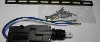
Standard alarm remote control unit: dismantling and location
A couple of days ago, I received an email from a blog reader with a question about the remote control unit for the security alarm. I decided to write a short article to show where this module is located and how to remove it if replaced with a new one.
Where is the remote control unit for the security alarm on Kalina
This part is located under the rear seat, more precisely under the left half. In order to get to it, you must first raise the seat by pulling the cord:
And under the floor covering there is a part that interests us; in the photo below the approximate location is shown by an arrow:
Now below we will analyze in more detail the entire procedure, starting from removing the casing and ending with dismantling the module itself.
Removing and installing the standard alarm remote control unit on Kalina
Disconnect the negative terminal from your vehicle's battery.
To perform this repair, you will need a minimum of equipment and tools. The list of what you need is given below:
- crosshead screwdriver
- Head for 10
- Driver or ratchet
- Extension
So, first you need to unscrew the 4 bolts securing the plastic sill trim:
After this, freely remove this decorative trim:
Now you can start removing the floor covering, but there is no need to remove it completely. Simply lift it halfway to gain access to the alarm unit.
Now that you can remove it, you must first disconnect the plug with the wires. To do this, on the left side you need to press the plastic lock of the plug and pull it to the side:
In the end, this is the final result:
Now all that remains is to unscrew the two nuts securing the alarm unit itself through the holes, as shown in the photo below:
And the final step in this repair will be to remove the module from its seat:
If replacement is necessary, install this part in the reverse order of removal. This work is completed within 10 minutes and is not difficult.
Lada Kalina wagon 2009, engine Gasoline 1.4 liter., 89 hp, Front drive, Manual — electronics
Comments 6
It was similar, on the right side the station lifts did not work (even the buttons in the doors did not respond) if from the driver's door, there was a clicking sound in the block. The floor of the cabin was dismantled, they couldn’t find it, then an electrician connected the nubuck to a diagnostician and showed a short circuit on the right side, some wire under the rear seat was rotten
in coil motors - they should show a short circuit when checking
When I was digging towards the electronics control unit (the windows on the starboard side also moved jerkily and I had to wait until the unit either cooled down or rebooted) I came across records of people whose contacts in the driver's door connector or in the harness near the driver's left foot were green . Everything there was in new condition, and only replacing the comfort unit helped.
Describe what you did to the car before? Have you touched the immobilizer before? What additional electrical components are installed in the car (alarm, auto start, etc.) This is important in order to understand the problem.
On Kalina, the luxury electrical package consists of an immobilizer (the master unit for data exchange via the bus), a control unit in the driver's door and an electrical package control unit under the left rear seat. They communicate via a line bus. There are no relays in the fuse box that control the system. Only fuses. If I'm not mistaken, then there are 2 of them. One is responsible for the entire electrical package, the second for the immobilizer (namely the car starting function). The immobilizer in LC1 also performs the functions of turning on both front and rear foglights, controlling heated mirrors (signal transmission via the line bus) and interior lighting.
There is a problem that in the central left pillar the wires going to the left rear door begin to short out. Then the electrical system literally starts going crazy, rolling down all the windows, setting the alarm against its will, etc. Check this moment.
Overall the system is quite reliable.
The immobilizer was not touched at all. There is an additional alarm with auto start. There were symptoms - the rear window failed, then the driver's window began to move jerkily, a couple of cm at a time. I threw in a used window control unit and the comfort unit died completely. There was a strong burning smell; upon opening, 2 burnt mics were found. Then, by ringing, I discovered that both rear motors were closed. I disconnected the chips from them so as not to burn the new block. And for glass and locks to malfunction, this did not happen.
There is a 99% probability - a short circuit in the central pillar. This is exactly what happened to me.
Where is the Priora comfort block located?
To gain access to the product, you will need to unscrew the protective plastic walls of the car's center console. They are located on the left side of the front passenger seat and on the right of the gas pedal, on the driver's side. The device itself is located above the control unit. In order to remove the device you will need a 10 mm wrench and a Phillips screwdriver.
Pinout of the Priora comfort block
The main, important elements of the device are:
- The so-called control drivers. Each driver is responsible for a set of specific functions.
- Transponder receiver.
- Relay control.
- Transceiver. Communicates with the module installed in the door.
- 2 connectors. The first is responsible for supplying power, the second for transmitting the necessary technical information.
Click to enlarge
To ensure proper operation of all elements connected to the comfort unit connectors, it is necessary to study the correct pinout (numbered diagram for connecting wires to contacts). The design of the comfort block for the Priora, when studied in detail, is not particularly difficult.
Double-glazed window control unit “Norma” 1118 – 6512010 for VAZ 11183 “Kalina”
©Aktuator On cars of the Kalina family, 2 types of non-interchangeable (by wiring) glass control controller 1118 - 6512010 and 11180 - 3763040 can be installed. 1118 – 6512010 has one 25-pin connection connector, 1118 – 3763040 (1118 – 3763040 – 10) – two connectors.
Remote control system for double-glazed windows “norm” on a VAZ 11183, Kalina. Controls power windows and central door locking. When the connector is removed, the engine does not start; the device performs some of the anti-theft functions.
Connection
* A regular shock sensor from any alarm system (Alligator, Saturn, Clifford, APS) is suitable.
+ 12 V connect to pin 12; body – on the 6th; We connect the signal wire (a ground appears on it at the moment of activity) to the 1st contact.
During normal arming, Kalina now reacts to an impact on the body (it sounds a horn and blinks turn signals). Similarly, instead of a shock sensor, you can connect a volume sensor (for example, single-level MMS‑1).
You can also connect a pager: + 12 V of the pager transmitter on pin 12, minus on pin 21.
Double-glazed window control unit 1118 – 3763040 (- 10 ) for VAZ 11183 “Kalina”
| Appearance | Controller board | Reverse side |
Double-glazed window control unit 2170 – 3763040 for VAZ 2170 “Priora”
| Appearance | Controller board |
1 . 1 Malfunction in the VZ communication coil circuit
1 . 2 Malfunction in the circuit from the block to the communication coil to the APS ECU
1 . 3 Transponder missing in OK
1 . 4 The transponder in OK is faulty (detected during pre-production preparation)
1 . 5 The transponder in the Republic of Kazakhstan is faulty (detected during pre-production preparation)
1 . 6 Malfunction of the input transponder circuit in the APS ECU
1 . 8 The communication coil came off from the VZ pad on the inside
2. 2 Malfunction of W‑Line circuits in the APS or ICS units
2. 3 Lack of supply voltage on the APS or KSUD unit
2. 4 The “Normal” electrical package is faulty (the control driver has burned out)
2. 5 KSUD does not contact
Abbreviations: IS – status indicator; VZ – ignition switch; OK – training key; RK – working key; RC – remote control; KSUD – engine control system controller; ECU - electronic control unit
Removing and installing the standard alarm remote control unit on Kalina
Disconnect the negative terminal from your vehicle's battery.
To perform this repair, you will need a minimum of equipment and tools. The list of what you need is given below:
- crosshead screwdriver
- Head for 10
- Driver or ratchet
- Extension
So, first you need to unscrew the 4 bolts securing the plastic sill trim:
After this, freely remove this decorative trim:
Now you can start removing the floor covering, but there is no need to remove it completely. Simply lift it halfway to gain access to the alarm unit.
Now that you can remove it, you must first disconnect the plug with the wires. To do this, on the left side you need to press the plastic lock of the plug and pull it to the side:
In the end, this is the final result:
Now all that remains is to unscrew the two nuts securing the alarm unit itself through the holes, as shown in the photo below:
And the final step in this repair will be to remove the module from its seat:
If replacement is necessary, install this part in the reverse order of removal. This work is completed within 10 minutes and is not difficult.
Source