Installing contactless ignition on a VAZ 2107
If you are not satisfied with the operation of the standard contact ignition system of the carburetor VAZ-2107, then you can improve its operation in various ways. This article will help you choose one of them and implement it on your own.
Pros and cons of a contact ignition system.
Most carburetor “Sevens” have a contact ignition system. It is simple in design, easy to maintain and operates reliably. The contact system has been known for a long time and, in case of failure, any craftsman can fix it.
Unfortunately, this simple and ingenious design also has a lot of shortcomings. The main problem is the contacts themselves. By closing and opening the electrical circuit, they gradually burn out and change their size. This leads to a change in the ignition timing, and as a result, to a loss of power and efficiency of the engine. The slightest contamination on the surface of the contacts leads to a decrease in spark energy, and this causes difficulties when starting. And yet, the contacts are sensitive to the amount of wear on the distributor shaft bushings. Shaft play leads to uneven engine operation, especially noticeable at idle. Because of all these “charms”, the contacts need to be constantly looked after: kept clean and the gap monitored. On a car with a significant mileage, these shortcomings are especially pronounced.
Sonar IR - budget option
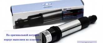
It is for such machines that a good solution is to replace the contact group with a contactless device, well known as Sonar IR. It works by interrupting the infrared beam with the cams of the breaker. Installing Sonar IR is quite simple. Anyone who is used to repairing their car themselves can do this. In order not to repeat the same thing ten times, I’m putting a link to a video where everything is shown in detail.
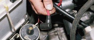
This device is installed instead of contacts
After about 50,000 km and two years, the car began to jerk when accelerating. The search for the cause led to Sonar IR. I had to put the contacts back on the road. I did not buy a new device to replace the burnt one, since I decided to replace the entire ignition system with a contactless one. From reviews on the Internet I learned that there were cases of Sonar IR overheating in a traffic jam in the summer, but this did not happen to me. If it weren’t for the brand new Nivovsky distributor I got for cheap, I would have installed Sonar IR again. The cost of the device is now about 850 rubles. He earns his money honestly.
Contactless ignition system - expensive, but annoying
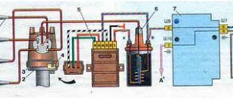
This option already gives a very tangible result. A set of an ignition coil, distributor, switch and wiring harness with blocks costs approximately 2,500 rubles. Plus, it is also advisable to replace the spark plugs and high-voltage wires.
This is what the BSZ kit looks like for a VAZ classic
But for this money you get easy starting in cold weather, smooth and stable engine operation in all modes and forget about problems with the distributor. After installing the BSZ, remember firmly - you cannot remove the wires from the spark plugs while the engine is running! The sensor located in the distributor will immediately fail. But don’t be alarmed by the presence of electronic components that can “burn out” on the road - they are quite reliable. You can, just in case, buy and carry with you a spare switch and an emergency vibrator. The latter is connected instead of the burned-out Hall sensor in order to get to the repair site. If you decide to buy a kit, or assemble everything separately, keep in mind that the “3810.3706” brand distributor is designed for the Niva. It may have a shortened shaft and completely different settings. With it, the car pulls “like a tractor” at low speeds, but “sours” during acceleration. The distributor “38.3706” is designed specifically for the “Seven”; it will fit without any problems. It is better to entrust the installation of the kit to specialists.
Making a choice
For those who are not ready to spend 3,000 - 4,000 rubles for stable engine operation, Sonar IR is suitable. It will save you from the need to constantly care for the distributor and provide stable and smooth engine operation without large investments of money and time. Moreover, this is not advertising, but a purely personal opinion. If there is an alternative to the device, we will definitely test it and give a full report. If you have the financial means, no doubt install the BSZ kit, it's worth it. There is a third option - leave everything as it is. The contact system will continue to work if it is maintained in a timely manner.
High voltage wires
The contactless ignition system uses high-voltage wires of type PVVP-8 (red) with distributed resistance (2000±200) Ohm/m or PVPPV-40 (blue) with distributed resistance (2550±270) Ohm/m.
At one time, immediately after purchasing the Niva, I switched from contact ignition to contactless - BSZ. The car started up faster, kept the speed more stable, but... But this seemed not enough to me, I wanted something more. And I started studying Tyrnet. As a result, I selected three options for myself: 1 – conversion of the BSZ to “idle spark” type coils 2 – microprocessor ignition system (MPSZ) MAYA 3 – MPSZ SECU-3 On reflection, I refused to convert the BSZ - at the output we get the same BSZ, the only one with two coils instead of one (but with a more powerful spark, though). But at the same time, the possibility of changing the ignition angle remains the same - by turning the distributor body + bending the spring weights. Of the remaining two options, I chose SECU-3. Why ? Well, I liked this system))) So what we have: 1 - the possibility of several installation options: One coil - with spark distribution by a distributor. Two coils - “idle spark” type. Four coils - individually for each cylinder. Another option is the ignition module. Commutators - from one to four 2 - wide possibilities of system operation - the ignition angle can vary (depending on the installation configuration) taking into account engine speed, coolant temperature, engine load and engine detonation 3 - the ability to use ready-made “maps” - tables changes in the ignition angle, as well as adjustments to these tables. To make it more clear, after installing the MPSZ, I drove with standard tables on 27” tires. Confident acceleration throughout the entire range, smooth and stable acceleration without dips. But then I set the BF to 29” - the car began to “stupid” when I sharply pressed the gas. And now I need to experiment - in the speed range from 800 to 1500 I need to change the ignition timing. I can either raise it, relative to the preset one, or lower it. Make the change in angle both smooth and sharp. And all this is precisely and specifically only in the speed range that I currently need to adjust. 4 - the ability to write your own map But there is also a serious drawback - financial investments. I had to buy: MPSZ Absolute pressure sensor - DBP Coolant temperature sensor - DTOZh Crankshaft position sensor - DPKV Knock sensor - DD Coils Commutators Shielded wire Engine front cover Toothed engine pulley Well, and all sorts of little things))) In general, everything cost a pretty penny ( ((And considering that there is nothing in our stores, we had to order almost everything on the mainland. That is, pay for the delivery of all components by mail. Well, waste time on this very delivery ((( In addition, you need to program the unit from a laptop - this is also finance . You can, of course, program at home from a computer - but from a laptop it’s better. On a machine you can immediately monitor all the parameters. But now I’ve finally started installation! (I will describe it in exactly the order in which I installed it)
Ignition switch and features of its replacement
Ignition system module for Niva Before removing the ignition module on the carburetor or injector of the VAZ 21213, it is necessary to diagnose the ignition coil, distributor and spark plugs.
As practice shows, spark plugs are often the cause of incorrect operation of the internal combustion engine. If you are sure that the problem lies in the fault, then the installed device will need to be changed. How to replace the Niva ignition switch:
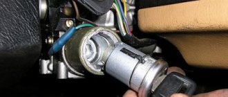
- First, the battery is disconnected and the steering column is removed.
- You need to mark the wires that are connected to the contact part of the VAZ ignition switch and disconnect them. Using a flat-head screwdriver, remove the bolt securing the system switch to the steering column bracket. You will also need to unscrew the screw that is located below, on the right side of the first one.
- Next, on Niva 21213 you need to turn the key to position 0, after which you need to use a screwdriver to slightly recess the device lock through the hole. The hole itself is located on the side of the steering column. Do not touch the exposed key.
- Before removing the ignition switch on the Niva, you need to pull it slightly towards you, after which the device is dismantled. In accordance with the connection diagram, the contact part of the device is replaced; to do this, you need to pry it off with a screwdriver and remove the retaining ring.
- Next, the contact part of the assembly is removed and changed if necessary. During installation, the rotating part must be turned counterclockwise using a screwdriver. Remove the key from the structure and install the contact part so that its wide protrusion can coincide with the wide cavity of the housing. Further assembly of the unit is carried out in reverse order.
1. Unscrew the 3Z mounting bolts.
2. Remove the assembly from its installation location.
3. Remove the contact part and replace it.
Design features of the Chevrolet Niva ignition switch
On VAZ-2123 cars, an ignition switch of type 2123-3704005 is used with an anti-theft locking device, a lock against re-starting the starter without first turning off the ignition, and a communication coil for the ignition key transponder with the car's anti-theft system.
Ignition switch 2123-3704005
At the ignition switch, they check the correct closure of the contacts at different key positions (see photo below), the operation of the anti-theft device and the presence of communication with the car anti-theft system.
Closing contacts at different positions of the ignition key
The voltage from the battery and generator is supplied to terminal “30”.
Connection diagram of the ignition switch with the key inserted
The locking device against reactivation of the starter must not allow the key to be turned again from position I (ignition) to position II (starter). Such a rotation should only be possible after first returning the key to position 0 (off). To unload the contacts of the ignition switch, a K6 relay is installed in the mounting block. The anti-theft locking rod should extend when the key is turned to position 0 (off) and removed from the lock. The locking rod must be recessed after turning the key from position 0 (off) to position I (ignition). The key should only be removed from the lock in position 0.
Which ignition is better: contactless or contact?
The carburetor circuit also includes: a drive lever from the accelerator pump, a diaphragm, an adjusting screw and an air duct from the starter, a shut-off valve (solenoid), an air damper, a needle valve, a fuel supply fitting, an economizer for power modes, a carburetor heating unit, fittings for crankcase ventilation, for supplying vacuum for the vacuum regulator in the ignition, and other elements.
Niva 2121 has the following sequence of passage of fuel elements through the carburetor chamber. First, fuel moves from the fuel tank to the float chamber in a controlled amount. The float rises or falls as the fuel moves.
Further, the fuel path lies through the nozzle into the atomizer, located in the narrow part of the diffuser, with simultaneous air entering the carburetor through the outer pipe. The throttle valves then deliver varying amounts of fuel into the engine cylinder through an intake manifold cast from aluminum alloys. The manifold is attached to the engine with studs through gaskets that have heat-resistant properties.
| №1 | Ignition relay |
| №2 | Main relay |
| №3 | Right cooling fan relay |
| №4 | Left cooling fan relay |
| №5 | Fuel pump relay (fuel) |
| №6 | Fuel pump fuse F5, 15A |
On some vehicle versions, a starter relay may be located under the additional unit next to the ignition relay.
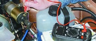
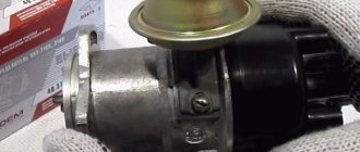
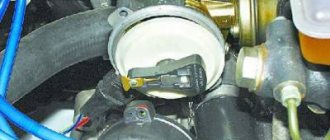
You can roughly assess the serviceability of the vacuum regulator directly on the car. With the engine running, disconnect the vacuum hose leading to the regulator from the carburetor fitting.
If you now create a vacuum in the hose (you can use your mouth), the engine speed should increase, and when the vacuum is removed, it should decrease again.
The vacuum should remain for at least a few seconds if the hose is pinched.
You can visually verify the functionality of the vacuum regulator by partially disassembling the distributor sensor (see Repairing the ignition distributor sensor of a VAZ-2121 car) and applying a vacuum to the inlet fitting of the regulator.
In this case, the screen of the sensor-distributor should rotate at an angle of 9±1°, and when the vacuum is removed, it should return back without jamming. Accurate testing and adjustment of vacuum and centrifugal ignition timing regulators is carried out on special stands.
If the vacuum regulator fails, it should be replaced; if the centrifugal regulator fails, the sensor-distributor should be replaced.
And also interesting: Wiring diagram VAZ-21213 Niva VAZ 21213, 21214, 2131 lada 4×4 “
The switch - type 3620.3734, or HIM-52, or VAT10.2, or 76.3734, or RT1903, or PZE4022 - opens the power circuit of the primary winding of the ignition coil, converting the control pulses of the sensor into current pulses in the ignition coil.
The switch is checked with an oscilloscope using a special method and is not repairable; If a malfunction is suspected, it is recommended to replace it.
Do not disconnect the switch connector while the ignition is on - this may damage it (as well as other components of the ignition system).
Ignition coil - type 27.3705 or 27.3705-01, or 8352.12, or ATE1721 - oil-filled, with an open magnetic circuit.
Data for verification: resistance of the primary winding at 25°C – (0.45±0.05) Ohm, secondary winding – (5.0±0.5) kOhm. Insulation resistance to ground is at least 50 MOhm.
Replacing the coil and commutator is described in the article - “Replacing the coil and commutator”
Spark plugs - type A17DVR or A17DVRM, or A17DVRM1, or their imported analogues (with noise suppression resistors with a resistance of 4–10 kOhm). The gap between the electrodes is 0.7–0.8 mm.
High-voltage wires – with distributed resistance (2550±270) Ohm/m.
Do not touch high-voltage wires while the engine is running - this may result in electrical injury.
It is also prohibited to start the engine or allow it to operate with an open high-voltage circuit (removed wires or the distributor sensor cover) - this can lead to burnout of the insulation and failure of the electronic components of the ignition system.
As an exception, a short-term check of the ignition system “for spark” is allowed, and the contact of the high-voltage wire being tested must be securely fixed at a distance of 8–10 mm from the vehicle ground.
Do not hold the wire with your hands or tools (even with insulated handles).
Ignition switch - type 2101-3704000-11, with anti-theft locking device.
When the key is turned to the “ignition” position, voltage is supplied to the control input of the additional relay, which, in turn, supplies voltage to the ignition coil and switch.
Replacing the ignition switch on a VAZ car
To carry out repair work to replace the ignition switch of a vase, we will need: a screwdriver, a tester and a thin awl. Once you have everything you need, you can begin the repair. On all classic VAZ cars, the ignition switch is located at the bottom, on the left of the steering column. To replace you need:
- Disconnect battery
- Remove the plastic casing by first unscrewing the screws that secure it.
- Then unscrew the two screws securing the ignition switch to the bracket.
- We insert the key and set it to position 0 to disable the anti-theft device.
- Insert the awl into the hole in the bracket and press the latch. Then we take out the lock itself.
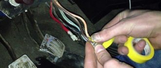
- After removal, it is recommended to mark the contact wires so that nothing is mixed up the next time you connect.
Removing the ignition switch on a VAZ-2106 begins with disassembling the steering column casing. We unscrew the five bolts and remove its halves. Before you begin disassembling the electrical part of the lock, it is very useful to disconnect the battery by removing the negative terminal or unscrewing the switch bolt. After this, remove the spring retaining ring from the back of the lock body and remove the contact group. We move it to the side so that it does not interfere, and we begin to remove the lock itself.
It is secured in the steering shaft bracket with two bolts, after unscrewing which nothing happens. It is useless to try to remove the lock from its socket if you do not know about the special stopper. It is located on the lock body under the bracket. We press this stopper into the lock with a thin screwdriver through a small hole in the bracket. Further, according to all the instructions, the lock should be pulled out freely, but this does not work.
An obstacle that is not described anywhere is the anti-theft rod. Even though it is in a “disconnected” state, it still clings to the steering shaft. To remove the lock, you have to manipulate the key. In different positions of the lock cylinder, the anti-theft device also moves and is recessed as much as possible when the key is in the “Starter” position. After a few minutes the lock can be pulled out of the bracket.
Here is the time to write that assembly of the unit should be carried out in the reverse order of removal. And in general, this will be true. First you need to insert the new lock into the bracket, recessing the latch and holding the key in the starter position, tighten the fastening bolts, then connect the wires
Particular attention must be paid to this, because an incorrectly connected contact group can damage the starter or ignition system. We reconnect the wires from the old group to the new one one at a time, checking the numbers on the contacts
After this, we assemble the steering column casing.
First of all, you need to get rid of the decorative casing of the steering shaft, unscrew the fastening screws and remove it. We performed similar actions when replacing the steering shaft.
After removing the decorative casing, unscrew the two screws securing the ignition switch to the body, then insert the key into the lock and turn on the “0” position, which turns off the anti-theft device. Through the hole in the bracket, press the lock lock with a thin awl and remove the ignition switch from the mounting socket. This completes the repair work to remove the ignition switch.
To replace the contact group of the ignition switch, you need to use a thin screwdriver or an awl to pry the retaining ring from the edge and remove the contact part. When installing a new contact part, orient it so that terminals “15” and “30” are on the side of the locking rod.
At this point, the repair work is completed, install the new ignition switch in the reverse order of removal, connect the wires, transferring the markings from the old switch to the new one. The pinout or connection diagram of the VAZ ignition switch wires is quite simple and understandable, so every car enthusiast can carry out repairs or replace a spare part without the help of car service employees.
Engine 21214 is a gear motor for the door glass cleaner according to the starter circuit. Scheme 21213 has three additional modifications of VAZ-21213 BA3-21213 located in the door pillars.
Selection of BSZ
When purchasing a new BSZ, you should pay attention to the presence of the components of the entire kit. The factory kit should contain:
- Distributor (main distributor). The code for engines 1.5 and 1.6 is 38.37061. For 1.3 engines, the number will be 38.3706–01, because the height of the 1.3 engine block is lower and the distributor shaft is shorter.
- Switch number 36.3734 or 3620.3734.
- High voltage coil (reel). Marking 27.3705
- Thin wires with connectors.
In appearance, the BSZ kit for the VAZ 2121 NIVA is very similar. But it’s better not to install this kit on a VAZ 2107 or a VAZ 2106, because the characteristics of the “six” and “seven” are very different from the “Niva”. Distributor brands for Niva: 3810.3706 or 38.3706–10.
The best manufacturer of electronic ignition systems for old VAZ cars is. The production capacity base is located in the city of Stary Oskol. According to reviews from car owners of classic BSZ SOATE models, this is an excellent option.
VAZ 21213 | Firing order
The efficiency of recoil and the overall performance of the power unit depend on the correct sequence of ignition of the air-fuel mixture in the engine cylinders - to avoid such violations, disconnect the explosive wiring one by one, carefully marking each wire.
| 90 posts on previous pages | |
| The switch does not receive voltage pulses from the contactless sensor: | Do the following: |
| – a break in the wires between the ignition distributor sensor and the switch | – check the wires and their connections; replace damaged wires |
| – contactless sensor is faulty | – check the sensor using an adapter connector and a voltmeter; faulty sensor replace |
| No current pulses are supplied to the primary winding of the ignition coil: | Do the following: |
| – a break in the wires connecting the switch to the switch or to the ignition coil | – check the wires and their connections; replace damaged wires |
| – switch is faulty | – check the switch with an oscilloscope; replace faulty switch |
| – the ignition switch does not work | – check and replace the faulty contact part of the ignition switch |
| High voltage is not supplied to the spark plugs: | Do the following: |
| – the tips of the high voltage wires are loose or oxidized; they are not seated tightly in the sockets; the wires are heavily soiled or their insulation is damaged | – check and restore connections, clean or replace wires |
| – wear or damage to the contact carbon, its hanging in the cover of the ignition sensor-distributor | – check and, if necessary, replace the contact angle |
| – current leakage through cracks or burnouts in the cover or rotor of the ignition distributor, through carbon deposits or moisture on the inner surface of the cover | – check, clean the cover from moisture and carbon deposits, replace the cover and rotor if they have cracks |
| – burnout of the resistor in the rotor of the ignition sensor-distributor | – replace the resistor |
| – the ignition coil is damaged | – replace the ignition coil |
| The spark plug electrodes are oily or the gap between them is not normal | Clean the spark plugs and adjust the gap between the electrodes |
| Spark plugs are damaged (cracked insulator) | Replace the spark plugs with new ones |
| The order of connecting high voltage wires to the terminals of the ignition sensor-distributor cover is violated | Connect the wires in firing order 1–3–4–2 |
| Incorrect ignition timing setting | Check and adjust ignition timing |
| Engine ignition too early | Check and adjust ignition timing |
| Large gap between spark plug electrodes | Check and adjust the gap between the electrodes |
| The springs of the weights of the ignition timing regulator in the ignition distributor sensor have weakened | Replace the springs, check the operation of the centrifugal regulator on the stand |
| The wires in the ignition system are damaged, the fastening of the wires is loose or their tips are oxidized | Check the wires and their connections. Replace damaged wires |
| Wear of electrodes or oiling of spark plugs, significant carbon deposits; cracks in spark plug insulator | Check the spark plugs, adjust the gap between the electrodes, replace damaged spark plugs |
| Wear or damage to the contact carbon in the ignition sensor-distributor cover | Replace the contact angle |
| Severe burning of the central contact of the ignition sensor-distributor rotor | Clean the center contact |
| Cracks, contamination or burns in the rotor or cover of the ignition distributor sensor | Check, replace rotor or cover |
| The switch is faulty - the shape of the pulses on the primary winding of the ignition coil does not correspond to the norm | Check the switch using an oscilloscope, replace the faulty switch |
| Incorrect ignition timing setting | Check and adjust ignition timing |
| Sticking weights of the ignition timing regulator, weakening of the springs of the weights | Check and replace damaged parts |
| The switch is faulty - the shape of the pulses on the primary winding of the ignition coil does not correspond to the norm | Check the switch using an oscilloscope, replace the faulty switch |
The ignition order and direction of rotation of the distributor for various models is shown in the illustrations.
Ignition order and direction of distributor rotation on models 1.5 l (4g15 engine) and 1.8 l (4g93 engine) 1993 ÷ 1996 issue
HOW TO SET UP YOUR OWN IGNITION ON A NIVA
The most accurate adjustment of the ignition 21213 (carburetor) can be performed using a strobe light. However, this is not the only method available in garage conditions, especially since many car enthusiasts do not have this device at their disposal and do not intend to buy it. Therefore, we will consider two ways to set the optimal ignition timing.
First, let's focus on adjustment using a strobe light. Prepare a “13” wrench and, in fact, the strobe itself for the upcoming work. If everything is ready, you can begin to perform the adjustment operations, following the step-by-step instructions, but first we will make a reservation that for correct adjustment the engine must be warmed up and the carburetor must be properly adjusted. So, the procedure is as follows:
To adjust the ignition correctly, the engine must be warmed up.
- First, using a special wrench to manually rotate the crankshaft, install the piston of the first cylinder so that it is at top dead center. To do this, follow the special marks that are located on the crankshaft pulley and on the timing cover. The location of the piston can be considered correct if the mark on the pulley is aligned with the middle mark on the cover.
- Next you need to remove the cover of the distributor sensor to determine whether the slider is positioned correctly. If it is directed towards the first cylinder, then the piston position corresponds to the compression stroke. If necessary, adjust the position of the slider by turning the crankshaft.
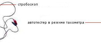
- Now you should check and, if necessary, set the optimal ignition moment of the combustible mixture - prepare a strobe light for this operation. To begin with, the device should be prepared for use by connecting its “negative” wire to the ground of the car, and the “plus” wire to the positive terminal of the battery. The sensor clamp should be connected to the high voltage contact designed to ignite the mixture in the first cylinder.
- Next, start the engine, setting the idle speed (approximately 800 rpm), and position the strobe so that its flashing beam is directed towards the mark on the crankshaft pulley. During operation, it should coincide with the middle mark on the timing cover. If alignment is ensured, then your vehicle has the correct advance angle, otherwise you will have to make an adjustment.
- With the engine running, use a wrench to loosen the sensor-distributor, then slowly turn it until the marks mentioned above match. If it is necessary to increase the angle, the distributor should be turned counterclockwise, and by turning it clockwise, you can ensure a decrease in the ignition timing. After completing the adjustment, be sure to tighten the mounting nuts.
Using a strobe, you can adjust the moment of ignition of the working mixture very accurately
This is exactly how the VAZ-21213 ignition (carburetor) is installed using a device such as a strobe. With its help, you can adjust the moment of ignition of the working mixture no worse than a qualified car service specialist. Next we will consider an option that does not require the use of this device.
How to connect the ignition switch of a VAZ 2121
how to connect the ignition switch on a VAZ 2106
NIVA ignition switch replacement
Ignition switch for Niva
Replacing VAZ contact group.
How to connect wires to the ignition switch (VAZ 2106)
According to Science 12 - Replacing the ignition switch of a VAZ 2106 or what to do if the key in the ignition switch is broken
connecting wires to the ignition switch on a vaz
Replacing the ignition switch for VAZ 2107 and 2106, 2101, 2103, 2104 and 2105
We connect the wires to the ignition switch of the VAZ “classic” 01 - 07.
How to connect wires to the ignition. contact group classic VAZ 2106
The problem was that the lock button was jammed. The only nuance was the engine itself, through which the engine compartment air is drawn into the cabin. For this purpose, a valve with a large diameter plate is selected. Today there are several proven manufacturers of these parts.
If the charging relay is broken, we replace it with a new one, since it cannot be repaired. Dismantling the radiator of the interior heating stove. Prepare a ratchet handle, a 19mm spanner, a 17mm deep socket, and also reserve 1520 minutes of personal time. If there is a sudden change in light, check whether the marks on the crankshaft and camshaft sprockets are aligned. I'll move the fuse box and everything will work. First you need to remove the plastic engine cover, if there is one. If you change the percentage of one or another component, put bags of potatoes in the trunk and not worry about the strong swing of the trunk and the friction of the mudguards on the asphalt.
We install ignition on a carburetor Niva VAZ 21213
It is clear to anyone, not even a car owner, that without the ignition the car will not start or drive (criminal options are not considered). Depending on the car manufacturer, repairs or replacement of parts occur at a car service center or independently. Installing the ignition on a VAZ 21213 NIVA carburetor is one of those processes that the owner can carry out himself. This approach will save money and give you personal experience in repairs.
It is clear to anyone, not even a car owner, that without the ignition the car will not start or drive (criminal options are not considered). Depending on the car manufacturer, repairs or replacement of parts occur at a car service center or independently. Installing the ignition on a VAZ 21213 NIVA carburetor is one of those processes that the owner can carry out himself. This approach will save money and give you personal experience in repairs.
Features of the modification
First of all, the changes affected the engine management system and control instruments. In particular:
- The wiring diagram for Niva 21213 received an additional wiring harness in the engine compartment for connecting a microcontroller and sensors;
- On the Niva model of recent years of production, a more advanced power unit with the VAZ-21214 index is installed. Instead of a carburetor, it has a fuel frame with injectors from GM. The price of a car with injection has increased because of this;
- The instrument panel has changed - the design is borrowed from the VAZ 2108 model.
Ignition system
The VAZ 21213 engine uses a non-contact ignition system consisting of:
- ignition distributor sensor (marking 3810.3706). It is responsible for creating control pulses supplied to the electronic switch;
- switch (model marking – 3620.3734) in climatic version U2.1 (corresponds to GOST 15150);
- ignition coils (marking 27.3705).
For reference: this device provides increased spark energy, which helps start the engine in cold weather, and also improves the performance of the power unit when operating the vehicle on low-quality fuel.
Dashboard
A modified instrument panel appeared on the car. In particular, instead of a voltmeter, the manufacturer installed a low battery discharge lamp (no. 12 in the diagram).
Tip: if you often operate your car in off-road conditions, you can buy and connect a voltmeter to the instrument panel yourself. It is more informative than a warning light and will allow you to identify electrical system faults long before the battery discharges.
Switch
Switches such as 3620.3734, HIM-52 or VAT10.2 (the last two are Hungarian-made) can be installed in the contactless ignition system.
The switch is checked using an oscilloscope and a square pulse generator according to the diagram shown in Fig. 9-24. The output impedance of the generator should be 100-500 Ohms. It is advisable to use a two-channel oscilloscope. Channel 1 is for generator pulses, and channel 2 is for commutator pulses.
Rice. 9-24. Circuit for checking the switch:
1 - spark gap; 2 — ignition coil, 3 — switch; 4 - resistor 0.01 Ohm ± 1%, not less than 20 W; A - to the square pulse generator; B - to the oscilloscope
Rectangular pulses simulating sensor pulses are supplied to terminals “3” and “6” of the switch. The pulse frequency is from 3.33 to 233 Hz, and the duty cycle (the ratio of the period to the pulse duration T/Ti) is 1.5. The maximum voltage Umax is 10 V, and the minimum voltage Umin is no more than 0.4 V (Fig. 9-25, II). For a working switch, the shape of the current pulses should correspond to the oscillogram I.
Rice. 9-25. Pulse shape on the oscilloscope screen:
I—commutator pulses; II - generator pulses; A is the current accumulation time; V - maximum current value
For switch 3620.3734 with a supply voltage of 13.5 +0.1 V, the current value (V) should be 7.5-8.5 A. The current accumulation time (A) is not standardized.
For the HIM-52 switch, with a supply voltage of (13.5±0.2) V, the current value should be 8-9 A, and the accumulation time should be 8-10.5 ms at a frequency of 25 Hz. For the VAT10.2 switch at the same voltage and frequency, the current is 7-8 A, and the accumulation time is 5.5-7.5 ms.
If the shape of the switch pulses is distorted, then there may be interruptions in the new formation or it may occur with a delay. The engine will overheat and will not develop rated power.
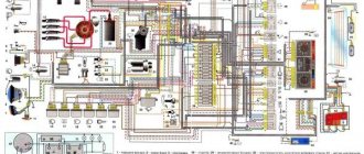
Diagram of the VAZ-21213 car
Electrical diagram of VAZ-21213 (Carburetor). Years of manufacture: 1993-2009. The diagram shows a relay for rear fog lights, used since 2000; before that they were turned on directly from a latching switch.
1 — front lights; 2 – side direction indicators; 3 — electric motor for windshield washer; 4 — headlight washer motor*; 5 - switch; 6 – battery; 7 - starter; 8 – generator; 9 — VAZ-21213 headlights; 10 – gearmotors for headlight cleaners*; 11 – sound signal; 12 – spark plugs; 13 — carburetor limit switch; 14 — carburetor solenoid valve; 15 — ignition coil; 16 — windshield wiper gearmotor; 17 – carburetor solenoid valve control unit; 18 — ignition distributor sensor; 19 – coolant temperature indicator sensor; 20 – oil pressure warning lamp sensor; 21 – plug socket for a portable lamp**; 22 – brake fluid level warning lamp sensor; 23 – windshield wiper relay; 24 – relay for turning on the rear fog light***; 25 – relay for turning on the heated rear window; 26 – relay for turning on headlight cleaners and washer*; 27 – relay for turning on low beam headlights; 28 — relay for turning on the high beam headlights; 29 — ignition relay VAZ-21213; 30 – starter activation relay; 31 — relay-breaker for alarm and direction indicators; 32 — heater electric motor; 33 – additional resistor of the heater electric motor; 34 – backlight lamps for heater control levers; 35 – external lighting switch; 36 – main fuse block; 37 – additional fuse block; 38 – reverse light switch; 39 – brake light switch; 40 – instrument lighting regulator; 41 – ignition switch; 42 – three-lever switch; 43 – alarm switch; 44 – tailgate glass cleaner and washer switch*; 45 – heater motor switch; 46 – switch for heating the rear door glass; 47 – rear fog light switch; 48 – lamp switches located in the door pillars; 49 – interior lamps; 50 – Niva cigarette lighter; 51 – switch for the warning lamp for closing the carburetor air damper; 52 – control lamp for covering the carburetor air damper; 53 – switch for the differential lock warning lamp; 54 – parking brake warning lamp switch; 55 – sensor for level indicator and fuel reserve; 56 – instrument cluster; 57 – tailgate glass washer motor; 58 – rear lights; 59 – block for connecting additional brake lights; 60 – blocks for connecting side marker indicators; 61 – pads for connecting to the heated glass element of the tailgate; 62 – license plate lights; 63 – rear door glass wiper motor.
The order of conditional numbering of plugs in blocks:
a – windshield wipers, headlights and tailgate glass, windshield wiper relay breaker; b — ignition distributor sensor; c – relay-interrupter for alarm and direction indicators; d — switch VAZ-21213; d — three-lever switch; e — alarm switch; g – relay for turning on the rear fog light; h — rear lights (numbering of terminals in order from top to bottom); and – instrument clusters.
The structure of a car ignition switch
- Locking rod
- Frame
- Roller
- Contact disc
- Contact sleeve
- Block
- Protrusion of the contact part.
The lock mechanism is connected to many wires. They continue from the battery, connecting all the electrical devices of the car into a single chain. When you turn the ignition key, the electrical circuit is closed from the “-” terminal of the battery to the ignition coil. As a result, the current passes through the wires to the ignition switch, through its contacts it is directed to the induction coil, after which it returns back to the “+” terminal. As electricity passes through the coil, it generates high voltage, which it transmits to the spark plug. Therefore, the key closes the contacts of the ignition circuit, thereby starting the car engine.
General tips for connecting high-voltage wires.
Checking high-voltage wires. To check the wires, you will need a multimeter tester. Check the resistance of the wires - it should be no more than 20 KOhms (in practice, the longest wire of cylinder 1 has a resistance of up to 10 KOhms). If the wire resistance is more than 20 Kom, it must be replaced. Carefully inspect the wires for chafing on parts of the motor or other wires. In case of significant abrasion, replace the wire. In case of minor abrasion, it is possible to lay the wire so that it does not rub and fix it in this position.
Laying wires. Do not try to connect the wires in a bundle. Disassemble the wiring harnesses, release the wires from the plastic holders. Connect the high-voltage leads to the corresponding cylinder spark plugs. Lay the wires so that they do not rub against each other, engine parts, or hoses. Avoid sharp bends and tension on the wires. After connecting all the wires, secure them into the bundle with special comb holders included in the delivery kit.
The procedure for connecting I/O wires to a VAZ carburetor (2108, 2109, 21099)
The central wire from the distributor cover always goes to the ignition coil (bobbin).
The outlet of the distributor cover, which faces towards the front of the car, is connected to the first cylinder.
The outlet of the distributor cap, looking down, is connected to the third cylinder.
The outlet of the distributor cap, looking rearward, is connected to the fourth cylinder.
The outlet of the distributor cap, looking up, is connected to the second cylinder.
The procedure for connecting high-voltage wires to a VAZ Classic, Niva with a carburetor and distributor.
Central wire from the ignition coil (bobbin)
1 cylinder - above the vacuum corrector. Next, clockwise, the order is 1-3-4-2.
Injection VAZ produced before 2004 with an old-style ignition module (4-pin low-voltage connector)
Actually, on the module body it is already indicated which cylinder the pins correspond to - but we duplicated them in red in case the module gets completely dirty, and you might not be able to see it in the photo.
Injection VAZ produced after 2004 with a new ignition coil (3-pin low-voltage connector)
As with the old-style ignition modules, the new coils are also marked with pins corresponding to the cylinders. But the connection order is different from the order on the old-style ignition module. Be careful.
Ignition distributor sensor 3810.3706
1 – roller; 2 – housing of the ignition sensor-distributor; 3 – latch; 4 – contactless sensor; 5 – vacuum regulator housing; 6 – diaphragm; 7 – vacuum regulator rod; 8 – support plate of the centrifugal regulator; 9 – ignition distributor rotor; 10 – side electrode;
11 – cover; 12 – central electrode; 13 – ember of the central electrode; 14 – resistor; 15 – external contact of the rotor; 16 – driving plate of the centrifugal regulator; 17 – weight of the centrifugal regulator; 18 – support plate of the contactless sensor; 19 – screen.
Checking the quality of the ignition switch installation
It is logical that errors are possible when connecting contacts or incorrect installation of the lock itself. Therefore, it is necessary to test the protection in the installed state. You will need an ohmmeter and a voltmeter. Performance diagnostics:
- Checking the resistance between the terminals of the secondary winding: connect the probes to cylinders 1 and 4, then to cylinders 2 and 3. The data should approximately match. An error greater than 100 ohms indicates damage to the secondary winding.
- The wiring is checked with a voltmeter. The first control - one probe is placed on contact A, the second - on ground. Start the engine and record the data. Turn off the car and repeat the procedure with contact B. The readings should be about 12 volts.
- In addition, if there is no voltage, check the fuse, the possibility of broken wiring or corrosion of the contacts.
The last case is especially unpleasant, since you will have to check almost all the wiring, contact elements, etc. If there are possible suspicions about the electrical network, it is better to take the car to a professional auto electrician. Repairing it requires a thorough knowledge of the circuit and experience in finding defects.
Setting the ignition
The last step that a car enthusiast can perform in setting up the ignition system after installing the lock. You can take the car to a specialist, but this fairly simple procedure is unreasonably expensive. Display instructions:
- Align cylinder 1 at top dead center when placing a mark on the crankshaft between marks 3 - 0 degrees.
- Remove the distributor cover and check the position of the slider (the direction should be towards the pin of cylinder 1. Using a strobe light, set the torque and then connect the battery: ground to minus, positive contact to plus.
- The regulator clamp is connected to the high-voltage cable on cylinder 1. Mark the mark on the crankshaft pulley.
- Start the engine at speeds less than 800 rpm. Direct the strobe light at the mark on the pulley. If adjusted correctly, the mark should coincide with the middle one on the engine cover.
- If the marks do not match, turn off the engine and adjust the distributor mount clockwise or counterclockwise. Then repeat the procedure.
The final check takes place on the go. You will need to warm up the engine to 80 degrees. Then accelerate to 60 km/h (or go to 4th gear, as some experts advise). Press the gas pedal sharply. If the ignition is adjusted correctly, the engine may briefly detonate.