If the instrument panel does not work on a VAZ 2110, you need to understand the cause of the malfunction. It may be serious or minor. Often, to eliminate a breakdown, the panel has to be dismantled, but sometimes it is enough to replace the fuse or secure the ground wire.
What to do if the VAZ-2110 dashboard does not work
Owners of VAZ “dozens” have to deal with certain malfunctions during the operation of their iron horse. Some may take a few minutes to resolve, while others may take several days to resolve. It all depends on which part of the car has failed.
There are many problems, including with the instrument panel. Alas, the build quality of Russian cars is often far from ideal, and virtually any unit or component can suddenly fail.
Replacement
Now to the question of how to make replacements. To do this, we dismantle the old device and connect a new one in its place. Your steps look like this step by step:
Remove the negative cable from the battery, which will allow you to turn off the power to the car; Now disconnect the wires from the sensor and be sure to remember what form the pinout was in; The device can be dismantled by simply twisting it by hand. There is usually no need to use any tools. But if the device fits tightly, then use 22 or 21 millimeter keys. Depending on the modification of your “ten”, the design of the sensor may differ slightly; At the same time, we recommend checking the wiring; After removing the meter, unscrew the fixing nut that holds the wire going to the gearbox; Remove carefully so as not to drop the rod into the box. If this happens, you will have to completely disassemble the gearbox.
This is clearly not in your best interest; A new device with a rubber ring must be lubricated with transmission fluid so that the fixation in the new place is as reliable as possible; Assembly is performed in reverse order; Pay special attention to the pinout. Connect the multimeter with the ignition on
If the device showed “minus”, then you connected the wire to positive, which is absolutely not allowed. This is why we initially advised using a sensor that is not labeled 1, 2, or 3.
If you couldn’t avoid using a new device with inconvenient markings 1, 2 and 3, then remember an important pinout detail:
- 1 corresponds to “+”;
- 2 denotes signal output;
- 3 is “-“.
>
Start with the fuse
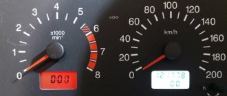
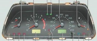
So, let's take a closer look at the situation when the instrument panel on a VAZ-2110 does not work (partially or completely), as well as possible causes and troubleshooting options. To do this, we first list the instruments and indicators available there:
- tachometer;
- speedometer;
- fuel level and coolant temperature indicators;
- 18 lamps – 6 panel lights and 12 control lamps;
- reserve socket for control lamp;
- 2 terminals for connecting wiring.
Regarding the latter, I would like to give a brief explanation on how to distinguish them on electrical circuits. In particular, the white block is designated as X1, the red block, respectively, as X2.
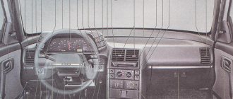
Another rather important point: VAZ-2110 cars can have one of two dashboard options. If it is an old model, then all devices are placed symmetrically. At the same time, the “Europanel”, in addition to the fact that it is more beautiful purely visually, is also distinguished by its coolant temperature and fuel level indicators shifted to the right.
If we talk about malfunctions of the VAZ instrument panel of the “tenth” series, then the most serious option is its complete failure, when neither the instruments, nor the indicator lamps, nor the backlight work. The first thing to do in such a situation is to check the 15-amp fuse located in the mounting block, marked F6.
If it turns out that it has burned out, it is best to immediately start looking for the root cause. Otherwise, the new fuse will most likely simply share the same fate as the old one. It can be damaged by a short circuit in the electrical circuit. If you lack the necessary skills, it is better not to waste time, but to hand the car over to a specialist who can not only detect the problem, but also fix it.
Tuning
This is what often causes the dashboard to malfunction. Perhaps the new shield was not fixed correctly, which is why it actually does not work. Either when installing the wiring, not all cables were connected, or they were simply bent. In such cases, only individual elements of the dashboard often stop functioning: for example, displays, battery, handbrake or oil pressure indicators, as well as the carburetor choke light. The instrument panel of the VAZ-2110 does not work after tuning - what to do in this case? The first thing to do is replace the wires. Usually, this allows you to easily solve the problem.
The problem may be caused by a ground wire
Sometimes situations arise when the needles on instruments behave completely inappropriately, jumping sharply from the minimum to the maximum mark and vice versa. In the vast majority of cases, the cause of this malfunction is the lack of normal contact with ground. There is nothing difficult in fixing this problem. First of all, you should find the fastening of the ground wire connecting the instrument panel to the partition that separates the interior from the engine compartment. It can be detected by removing the car radio from its standard socket.
However, there is one caveat here. If an alarm was installed on the car, then the fastening of the mass wire could well be moved to some other place. However, as a rule, the car owner is warned about such actions. In most cases, the fastening of the mass wire is moved to the area where the driver’s left foot is located, placing it behind the interior trim.
By the way, a situation where the arrows on the instruments begin to “jump” can also arise after installing the radio. In order to do this, you need to unscrew the ground wire coming from the dashboard. It happens that it is then screwed in poorly, and subsequently, due to body vibration, the contact becomes unreliable. To solve the problem, just twist the wire normally. It is worth noting that doing this is not very convenient, so you will have to make some effort.
The cigarette lighter is another possible cause of instrument panel failure. Often various additional devices are connected here. At the same time, many consumers require high current, and because of this, either fuse F19 blows or the cigarette lighter itself fails. The check in this case will be quite simple, provided that the fuse has not burned out, you need to disconnect the cigarette lighter connector.
If this is not the problem, then you will have to look for the cause directly in the instrument panel. It should be pulled out from its standard mounting location as far as possible, but do not disconnect the wires going to the pads. Next, we measure the voltage at the contacts indicated in the diagrams by numbers 6, 9 and 10. Everywhere there should be the same indicator - 12 volts. In addition, you should also check the ground wire on block X1 (white). Also inspect for possible damage to the tracks on the back of the instrument panel that supply electricity to the appropriate consumers.
Cigarette lighter failure
It is its malfunction that often causes the shield to fail. The fact is that many car owners turn on various devices through the cigarette lighter, for example, a special vacuum cleaner, chargers, pumps and other devices. Due to the fact that these gadgets require high current, either the socket itself or fuse F19 often breaks, as a result of which the instrument panel on the VAZ-2110 does not work.
In addition, the cigarette lighter may become damaged if left on for too long. In this case, you can return the instrument panel to functionality by disconnecting the socket block. But it is worth saying that such manipulation will be successful only if fuse F19 is functioning. If it does burn out, it must be replaced.
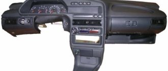
The device of the instrument panel on the VAZ 2110
The term “instrument panel” on cars refers to a block of warning lamps and indicators located in front of the driver. The correct name of the part is the shield, which is installed in a plastic panel called the dashboard.
The instrument panel on the VAZ 2110 includes:
- a device for determining the speed of movement - a speedometer;
- speed meter - tachometer;
- indicators of coolant temperature and fuel level in the tank;
- control indicator lamps equipped with yellow, orange, green, blue and red filters;
- lighting system (6 separate lamps);
- installation location of the warning lamp.
On VAZ 2110 cars it is possible to see several options for instrument combinations:
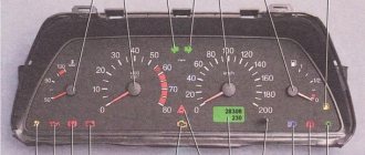
- The first releases used an electromechanical version of the panel with serial number 2110-3801010. Externally, the device is easily identified by a mechanical odometer mounted on the speedometer scale. Its drive is made from an electric motor, the rest of the indicators operate on a magnetic principle. On the back of the shield there are two connection blocks located at right angles.
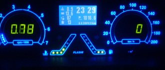
- Later, an electronic version of the dashboard appeared, equipped with a liquid crystal display on the bottom of the speedometer. There are “gauges” with a “suction” indicator (which was not installed on the VAZ 2110 with such a panel from the factory) or with an airbag lamp in the same place. There may be cars with a double display window - under the tachometer and speedometer.
- A very rare variant of the instrument cluster is designed for the VAZ 21106, equipped with a 2.0-liter Opel engine. The part number is 21106-3801010 and features an extended speed measurement range (up to 240 km/h) and an additional liquid crystal display on the bottom of the tachometer.
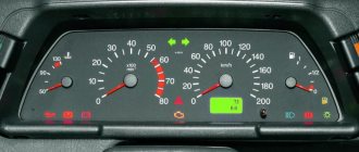
- On the latest versions of the VAZ 2110, a shield began to be used, unified with the 2118 Kalina car (model 1118-3801010), differing in the layout of the scales. Such a part is called a “new sample” panel among its owners. The device is installed in a modified type dashboard.
Electronic panel of the “new” sample Electronic panel of the “old” sample Electromechanical panel Shield for the Opel engine
Depending on the manufacturer and date of assembly, there are different designs for the VAZ-2110 instrument clusters. It is possible to digitize the tachometer in hundreds or thousands of revolutions, write technical information on the scale, etc.
vaz-2110-lada-110.jpg
The VAZ-2110 is a passenger front-wheel drive vehicle in which the power unit is located in a transverse position. The car is designed for use on roads “equipped” with hard surfaces. The car body is all-metal, four-door, monocoque, sedan type. In order to transport long and bulky cargo, the seats located in the rear of the cabin can be folded.
Thus, the volume of the trunk increases. The engines - carburetor or with different fuel injection systems - consist of four cylinders. Volume - 1.5 l. The model has significantly improved handling characteristics when compared with rear-wheel drive VAZs, thanks to its front-wheel drive layout.
This is especially noticeable on unsafe, slippery roads or when taking difficult turns. It is possible to equip the car with fog lights, electrically heated seats, practical electric windows, a modern on-board computer, a useful catalytic converter for gases that have “worked their way” in the exhaust system, as well as electric exterior mirrors that provide a rear view.
The car can also be secured with an electronic anti-theft mechanism, an airbag, air conditioning, an anti-lock brake system, and lighting using a sunroof.
Instrument panel pinout
The instrument cluster is connected to the vehicle's on-board network using plugs located on the rear wall. The connectors are made of white plastic (indicated as X1 in the diagrams) and red (X2 in the diagrams). Depending on the manufacturer, the pinout of the plugs is different. This point should be taken into account when performing repairs.
Placement of elements on the rear wall of the shield
Purpose of elements:
- 1 — fuel remaining lamp;
- 2 — panel illumination;
- 3 — right turn indicator;
- 4 — left turn indicator;
- 5 — white block X1;
- 6 — coolant temperature indicator;
- 7 — lamp for side lights;
- 8 — indicator of the switched on “suction”;
- 9 — control lamp for engine oil pressure;
- 10 — indicator of the applied parking brake;
- 11 — indicator of lack of battery charging;
- 12 — tachometer;
- 13 — Check Engine indicator;
- 14 — speedometer and red block X2;
- 15 — lamp for emergency brake fluid level drop;
- 16 — operation of external emergency signaling with turn signals;
- 17 — high beam indicator;
- 18 - a device that displays the fuel level in the tank.
Purpose of wires in the white plug of old-style combinations. The pin positions of the block are indicated in the diagram above.
| Pin number | Purpose | VDO wire color | Wire color Schetmash | AP wire color |
| 1 | Mass signal | Black | Black | Black |
| 2 | Tachometer from the engine control unit | Brown-red | Brown-red | Brown-red |
| 3 | Tachometer from ignition coil | Yellow | Yellow | Yellow |
| 4 | Constant positive supply (via fuse) | Red-blue | White-red | Red-blue |
| 5 | Liquid temperature signal | Green-white | Green-white | Green-white |
| 6 | Side lights (via fuse) | Yellow-black | Brown (2 pcs.) | Yellow-black |
| 7 | Choke indicator | Not used | Not used | Not used |
| 8 | Check Engine Light | White-red | White-red | White-red |
| 9 | Positive power supply (via fuse) | Orange (2 pcs.) | Blue | Orange (2 pcs.) |
| 10 | Likewise | Orange (2 pcs.) | Orange | Orange (2 pcs.) |
| 11 | Parking brake indicator | Brown-blue (2 pcs.) | Brown blue | Brown-blue (2 pcs.) |
| 12 | Generator terminal D | Brown-white | Brown-white | Brown-white |
| 13 | Signal from oil pressure sensor | Gray blue | Gray blue | Gray blue |
Purpose of wires in the red plug of old-style instrument clusters.
| Pin number | Purpose | VDO wire color | Wire color Schetmash | AP wire color |
| 1 | Outdoor air temperature sensor | Blue-red | Blue-red | Blue-red |
| 2 | Positive power supply (via fuse) | Orange | Orange | Orange |
| 3 | Negative signal | Black (2 pcs.) | Black | Black (2 pcs.) |
| 4 | Instrument lighting control | White | White | White |
| 5 | Right turn indicator | Blue | Blue (2 pcs.) | Blue |
| 6 | Same for left | Blue-black | Blue-black (2 pcs.) | Blue-black |
| 7 | Signal from brake fluid level sensor | Pink blue | Pink blue | Pink blue |
| 8 | Communication channel with the trip computer | Brown | Brown | Brown |
| 9 | Signal from vehicle speed sensor | Grey | Gray and yellow | Grey |
| 10 | Signal from fuel level sensor | Pink | Pink | Pink |
| 11 | High beam protection (fuse) | Green-black (2 pcs.) | Green-black | Green-black (2 pcs.) |
| 12 | Signal from alarm relay | Blue-white | Not used | Blue-white |
| 13 | Ignition switch control | White | Red | Red |
The pinout of the new panel is distinguished by the use of a single block with 32 contacts, some of which are not used.
| Pin number | Purpose | Note |
| 1 | Electric power steering | When installed on a VAZ 2110 it is not used |
| 2 | Alarm | — |
| 3 | Oil pressure | — |
| 4 | Hand brake | — |
| 5 | Standard immobilizer | When installed on a VAZ 2110 it is not used |
| 6 | Airbags | When installed on a VAZ 2110 it is not used |
| 7 | Side lighting | — |
| 8 | Right turn indicators | — |
| 9 | Left turn indicators | — |
| 10 | The engine control unit | — |
| 11 | Pad wear sensor | When installed on a VAZ 2110 it is not used |
| 12 | Seat belt indicator | When installed on a VAZ 2110 it is not used |
| 13 | traction control system | — |
| 14 | Controlling the on-board computer from the steering column switch | — |
| 15 | Brake fluid level sensor | — |
| 16 | ABS unit | — |
| 17 | High beam switch | — |
| 18 | Adjusting the backlight brightness | — |
| 19 | Negative power | — |
| 20 | Terminal "30" | — |
| 21 | Terminal "15" | — |
| 22 | Fuel consumption signal | — |
| 23 | Switching the computer menu forward | — |
| 24 | Switching the computer menu back | — |
| 25 | Negative external temperature | — |
| 26 | Positive external temperature | — |
| 27 | Fuel level sensor | — |
| 28 | Speed sensor | — |
| 29 | Engine temperature sensor | — |
| 30 | Low voltage tachometer signal | — |
| 31 | Diagnostic channel | When installed on a VAZ 2110 it is not used |
| 32 | Terminal L on the relay regulator | — |
Arrangement
So, what can you see on the instrument panel in this car? The combination consists of several components:
- antifreeze temperature indicator in Celsius;
- tachometer - number of revolutions of the power unit;
- right and left turn indicators;
- speedometer - vehicle speed;
- fuel reserve - the volume of fuel in the tank;
- image of a gas station - a signal about the need to refuel;
- control indicator for starting dimensions;
- brake fluid level indicator;
- starting high beam headlights;
- knob for adjusting the clock;
- display with total and daily mileage;
- alarm control indicator;
- clock screen;
- battery charge level;
- check engine - indicates an engine malfunction;
- indicator indicating the handbrake is engaged;
- oil pressure level;
- choke light - only available on carburetor engines.
What problems can arise with the instrument panel on the VAZ 2110?
The reasons why the instrument cluster stopped working are divided into two types:
- incorrect operation of the backlight or part of the indicators;
- complete shutdown of the panel.
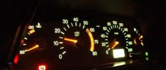
Instrument panel backlight does not light up
Several light bulbs are used to illuminate the combination. A darkened section indicates one or two burnt out bulbs. If the backlight fails completely, you should check the fuse responsible for the power circuit. It is located in the cabin block in the first place on the left in the top row, and has a nominal value of 5A.
The cause of the indicators not working may be problems in the electronics. So, a malfunction in the engine controller is a possible reason for the failure of the Check Engine lamp.
If, in the event of a complete failure of the instrument lighting on a VAZ 2110, the rear license plate lighting lamps and the left side side lights stop working, all these symptoms indicate a failure of the fuse link.
Complete node failure
Complete failure of the instrument cluster means turning off the dial indicators, warning lamps, and display. The main cause of the malfunction is the blown fuse located in the cabin unit. The 10 A insert is installed second from the right in the bottom row.
You can verify that the fuse has failed by looking at the direction indicators not working. If the new insert burns out, you should look for the problem in a short circuit in the wiring. It is forbidden to try to solve the problem by installing fuses of increased ratings or “bugs”, as this may cause a fire.
Arrows jump up and down
The reason for the chaotic movement of the arrows is a poor mass signal due to rotting or loosening of the wire fastening. According to the factory wiring diagram, ground comes from a wire attached to the engine panel. The bolt attachment point is located behind the audio system installation location. There may be other points for conducting the mass wire, obtained as a result of repairs performed by the previous owners of the car. After locating the contact point, you need to securely crimp the fastener and check the integrity of the conductor with a tester.
Instrument panel problem
On many used cars, instrument failures are often encountered due to the destruction of printed circuit board elements. To check, you need to pull the combination out of the panel without disconnecting the power supplies.
Cigarette lighter problem
A common cause of incorrect operation of the instrument panel on the VAZ 2110 is the cigarette lighter. When high-power consumers are connected, the fuse and the power supply to the instrument cluster located next to it burn out. The 25 A cigarette lighter insert is located to the left of the indicator panel (discussed in the complete unit failure section).
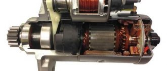
How to check the speed sensor
There is no need to talk about checking the DS on cars with a carburetor, since they use a cable system for transmitting torque directly to the speedometer, and there is simply no sensor. On cars with an injector, a DS is installed, the operation of which is based on the use of the Hall effect. The device is located on the gearbox near the exhaust manifold. This “neighborhood” leads to heating and chafing of the wires entering the block.
The performance of the speed sensor can be checked in several ways. To do this, the output electrical characteristics are measured using a portable oscilloscope or multimeter. The DS can be dismantled and the core can be rotated counterclockwise with a screwdriver. The oscilloscope screen should display a rectangular signal with a lower voltage value of 1 V, and an upper voltage value of at least 5 V. When the wheel is turned 1 revolution, 6 pulses appear at the output.
If there is a signal, but the speedometer does not work, a possible cause is a breakdown of the sensor drive. If the edges of the shaft are “eaten”, then the device will have to be completely replaced. If no signal appears when measuring the output characteristics, this indicates a malfunction of the sensor motor. Their measurement can be carried out without dismantling the primary device. To do this, you need to jack up the front wheel and, rotating it, take readings. It is more convenient to carry out such work with an assistant.
If, after replacing the sensor, the speedometer shows a speed that does not correspond to the driving mode, then the reason may lie in a breakdown of the DS drive gear. In this case, it is replaced along with the gear.
When purchasing a working drive, you need to pay attention to the number of teeth. If their number does not coincide with the standard gear, then the work will have to be carried out again
Diagnosis and troubleshooting
If the instrument panel of the VAZ 2110 does not work, then to fix the problems you need to:
- check the lamps and replace faulty elements;
- check the integrity of the wiring using a multimeter or test indicator;
- inspect the condition of the contacts and clean their surface from traces of oxidation;
- check the condition of the fuses;
- test the operation of the devices.
The diagram shows fuses in blue that need to be checked if problems arise with the devices on the VAZ 2110.
Instrument cluster circuit fuses
To check the temperature or fuel level gauge you must:
- Connect the ignition.
- Connect the positive power output of the device (attached to pin 5 in the white plug) to ground with a wire. If the arrow deviates, you need to check the condition of the wiring connecting the sensor and indicator.
- If the temperature indicator constantly indicates overheating, it must be disconnected from the sensor. If the needle drops to zero, the sensor needs to be replaced. Otherwise, there is a short circuit in the wiring to ground or failure of the indicator device itself.
- To test the device, you need to remove the white plug from the panel and apply power to pin 10 directly from the positive terminal of the battery. At the same time, a negative voltage is applied to pin 1. A working indicator shows a value equal to zero; if the arrow deviates, the device requires replacement.
Other possible repair options:
- Testing the tachometer is only possible on a stand that simulates engine operation. The speedometer is also checked using special equipment, which compares the measurement results with a reference device.
- After this, a visual inspection of the tracks on the printed circuit board located inside the combination is carried out. If cracks, ruptures and delaminations are detected, contact must be restored with solder. If repairs do not help, the instrument cluster will need to be replaced.
A video from the channel “In Sandro’s Garage” demonstrates how to replace backlight bulbs.
Precautionary measures
When repairing the instrument cluster, a number of recommendations must be followed:
- fuses are replaced with the ignition off;
- when testing devices, be careful to avoid short circuits;
- soldering is done with a low-power soldering iron with a thin tip;
- Removal and installation of the combination is carried out with little force so as not to damage the attachment points.
Expert recommendations
Some expert recommendations regarding diagnostics and repair of speakers:
- Diagnosis of the cause of unit failure should begin with a visual inspection of the speed sensor, as well as the wiring connected to it. As practice shows, the reason often lies in a broken wiring, in particular, in the place next to the plug.
- If the controller is covered with dust or oil, you need to dismantle it and wipe it thoroughly. Then you can put the sensor in place and try to check the performance of the speaker. There is a possibility that after these steps the speaker will operate normally.
- Under no circumstances should you drive with a non-working speaker, so if problems are found in its operation and you cannot check it yourself, you need to seek help from a specialist.
How to remove and disassemble the old-style instrument panel on a VAZ 2110?
To dismantle the instrument panel of a VAZ 2110, high qualifications are not required. Removing and installing another combination does not lead to immobilization of the car and the appearance of errors in the electronic units. The complex itself is equipped with a collapsible body and is divided into several components for repair or tuning.
What tools will you need to remove the panel yourself?
To remove and disassemble the instrument cluster, two screwdrivers are required:
- set of wrenches and sockets;
- short with a cross-shaped sting;
- regular length with a cross-shaped tip.
Preparatory work
Preparation for removing the instrument panel includes:
- turning off the power supply to the on-board network by removing the battery terminal;
- dismantling the steering wheel and column trim;
- glove box removal;
- a number of owners remove the front seats, freeing up additional space for work.
Instructions for removing the instrument panel
Step-by-step disassembly of the VAZ 2110 dashboard:
- Remove the screws securing the shield in the passenger's feet and the shield itself.
- Using a similar scheme, remove the shield from the driver's side.
- Remove the curved plug located under the parking brake lever.
- Remove the four screws securing the center console cover to the brackets. Attachment points are located on the sides, center and trailing edge.
- Disconnect the power window control key pads (if they are installed on the car). Remove the cigarette lighter connector.
- Remove the protective cover of the gear shift lever from the console cover housing. Dismantling is carried out carefully so as not to tear the cover.
- Remove the center console cover from the vehicle.
- Remove the warm air supply ducts to the rear seats.
- Unscrew the nuts securing the lower part.
- Remove the plastic trim on the front roof pillars.
- Remove the radio, heater control unit, clock, on-board display unit.
- Remove the plugs located along the top edge of the panel, in the area of the small non-adjustable deflectors.
- Unscrew the fixing nuts located underneath them.
- Unscrew the screws securing the casing along the lower edge. Two screws are located on the left, the third secures the diagnostic connector. Two more screws are located in the center of the dashboard, at the feet of the driver and passenger. Additionally, there are screws in the fuse box and in the cavity under the glove box.
- Remove the mounting block.
- Carefully remove the plastic casing from the seats. You may need to remove the plastic ties that secure the wiring.
Removing the shields in the legs Console cover screws Removing the front mounting points Separating the gear knob cover Removing the console from the floor Disassembled panel Side upper mounting points Panel removed View of the engine shield from the interior Another photo of the shield
Instructions for removing the instrument cluster
Sequence of steps for removing the instrument cluster:
- Remove the two screws securing the instrument cluster frame to the top. The screws have a head for a Phillips screwdriver; due to cramped space, a short tool or ratchet is used.
- Unscrew two similar screws securing the trim along the lower edge.
- Carefully remove the trim from its original place and bend it towards the steering column.
- For further dismantling, it is necessary to disconnect the wiring harnesses from the buttons installed on the sides of the cover. You can disconnect the wires on only one side and bend the trim to the side, but for greater convenience it is recommended to remove the part completely.
- Remove the two screws securing the instrument cluster to the dashboard frame.
- Pull the combination towards you, removing the metal hooks from the attachment points along the top edge.
- Unfasten the two connectors connected to the rear wall of the combination.
- Remove the instrument cluster from the panel.
Disassembling the instrument cluster is carried out as follows:
- Unfasten the back cover mounted on the plastic tabs.
- Unscrew the screws securing the protective glass.
- Mark the position of the arrows and then carefully remove. Some owners remove the hands using a table fork, placing it under the base. You can dismantle the part by hand - turning it counterclockwise with a little force and pulling it up.
- The substrate with the scales is a plate glued to a light-conducting panel.
Rear view of the instrument cluster Removing the cover Removing the glass Instrument panel without glass Arrows removed Peeling off the instrument scale
How to properly disconnect the wires?
When disconnecting the wiring plugs, do not apply significant force or swing the connection. Over time, plastic becomes brittle and brittle. Therefore, the plug is removed by pulling and applying vertical force. Before reinstallation, you can lubricate the surfaces with a special lubricant that prevents moisture from getting inside.
Procedure
Now let's figure out how to remove the drive when the speedometer on a VAZ 2109 does not work:
- To do this, release the cross member that secures the gearbox to the body, give back the nut that secures the drive
- Pry off the drive housing with a flat screwdriver (as in the photo below)
- By pressing the gearbox to the side (for example, with a piece of pipe) from the drive, we pull the drive out of it
- Then we check its serviceability
- To do this, twist the gear and see whether the groove for the speedometer cable begins to turn or not
- If the groove does not turn, then replace the speedometer drive
- When going to the store for a new drive, it’s better to take the old one with you as a sample just in case (you can confuse the number of teeth on its gear)
- And if you install a “foreign” (not the one you need) drive, then in no more than 100 meters it will break the box cover, because a mismatched gear pitch will simply turn the entire drive outward and result in serious damage to the gearbox
- To be able to use this gearbox in the future, it will be necessary to replace its rear cover and completely change the oil
- If the old one suddenly pours out, there will still be fragments and crumbs of the housing left in it, which can subsequently fall on a gear tooth or clog the oil channel
Now that you know how to determine what the reason is if the speedometer needle suddenly starts jumping and fix it with your own hands.
Drive repair
We only considered replacing the drive, if the speedometer does not work in the VAZ 21093, sometimes this is easier and cheaper to do:
- The speedometer drive is removed, as a rule, to replace its housing, or the sealing ring from under which lubricant flows, or the drive gear itself
- It can be removed without dismantling the gearbox assembly; for this purpose it is better to drive the car onto an overpass, inspection hole or lift
The repair procedure will look like this:
Using a socket wrench, unscrew the bolt that secures the drive housing, pry it off with a screwdriver, then remove it
Unscrew the drive nut, remove it, then pry off the housing with a flat screwdriver and remove the drive
Now we can remove the driven gear. This gear is made of plastic, so it is important to carefully inspect it and if you find signs of wear, replace it immediately
We inspect the condition of the rubber seal (shown by the arrow), then remove and inspect the plastic gear
In addition, it is important to pay attention to the condition of the mounting socket, where the tip of the flexible rod (cable) of the speedometer enters. The socket should not have licked corners or be broken, otherwise such defects will be the reason for replacing the gear. It is also worth paying attention to the condition of the box body in that place , where our drive is installed. If traces of lubricant leaks are visible, then it will be necessary to replace the rubber ring of the drive seal, which is located on its body. To remove it, you will need to remove the driven gear, then push the sealing ring out of the groove. All parts are then washed in clean kerosene
Of course, no one has canceled the service station services, if you are too lazy to tinker, although tinkering is probably not an applicable expression here (it only takes 10-20 minutes), and the price of their services suits you, then decide for yourself.
Replacing the cable
Almost everywhere, car owners are faced with the problem of speedometer failure, which is often caused by a faulty cable. To replace the cable, it is not at all necessary to go to a car service center, because you can easily cope with this task yourself, our instructions will help with this. So:
Go down the car (on a pit or overpass), then you need to unscrew the cable from the drive of your speedometer, located on the side of the engine compartment, move the rubber cover up, and unscrew the nut on the cable. After that, disconnect the cable. To disconnect the cable from the speedometer, you must first remove the instrument panel from dashboard In this case, if your car has a low dashboard, then unscrew two bolts and carefully remove the visor, squeezing the spring-loaded clamps with your fingers. Then you can remove the instrument cluster. If the car has a high dashboard, then first you will need to remove the trim, then unscrew the unit instruments Then you should unscrew the cable nut from the speedometer from the back side, and pull out the old cable through the engine compartment, remember how it went through. Because the next step you will have is laying (pulling) the new cable. Inserting the plug into the compartment bulkhead will be much easier , if you pre-lubricate it with oil, for example Litol
Installation of a new instrument panel on a VAZ 2110
Due to the different geometry of the combination of the new and old sample, three installation methods are possible:
- with adjustment of a new type of combination to the dimensions of the instrument panel;
- installation of a completely new instrument panel;
- with the installation of the so-called Euro pad (an extremely rare case, since the part is not on sale).
The fitting procedure is as follows:
- Trim the mask along the bottom edge. Trimming is done with a knife, soldering iron tip or other tool. The upper part is adjusted by heating with hot air.
- Putty the transitions of the mask, using the new devices as a template.
- Sand the transitions, sealing possible defects with putty.
- Perform final surface grinding.
- Coat the part with primer and paint it in the desired color.
- Install parts on the car.
Photos of the process of fine-tuning the VAZ 2110 mask for installation of a new sample combination.
Preparing the mask Puttying the opening Fitting parts Final result
Installation of the Euro trim is carried out on the removed instrument panel. Instead of the removed old shield from the VAZ 2110, it is possible to install a part from Priora. But for all components to work properly, you will need to connect parts of the old and new wiring, which is a difficult task.
Device connection diagram
The wire connection is shown in the diagram. Since factory wiring adapters are not available, owners make homemade harnesses. To assemble it, you will need a plug for the new dashboard and two plugs removed from the old type combination.
Standard connection diagram for a new “tidy”
How to check DS?
First, we check for the presence of grounding and 12 V voltage in the contacts. Such contacts are checked by dialing. And the contact of the pulse signals is checked during torsion.
The voltage between the output and the ground of the working speed sensor ranges from 0.5 V to 10 V.
Checking with a voltmeter:
- Remove the sensor.
- Connect one contact to the pulse signal terminal. We connect the second contact to the ground of the car.
- Next, we turn the speed sensor and see if signals are sent when the cycle is running and measure the output voltage of the DC. To rotate the sensor axis with your own hands, you need to put a tube on the sensor axis and twist it at a speed of up to 5 km/h. The faster you rotate the sensor axis, the more voltage the voltmeter will show.
Without removing the sensor from the car
- We put the car on a jack (jack up one wheel).
- We connect a voltmeter to the contacts of the car speed sensor.
- Spin the raised wheel and see if tension appears. A working sensor should show voltage and frequency (Hertz).
Using a light bulb or control
- Disconnect the pulse data wire from the sensor.
- We jack up one wheel.
- Turn on the ignition and look for “+” and “-“ using the control.
- Use the control to connect the “Signal” wire and turn the wheel by hand. If the sensor is working properly, the control should show a “-” (minus) signal.
In the absence of control, diagnostics can be carried out using a regular 12 V light bulb and a piece of wire:
- We take the wire and connect one end to the “plus” of the battery. We connect the second end to the “Signal” contact.
- Then we spin the raised wheel. The light should blink if the machine speed sensor is working.
The most common cause of this breakdown is a violation of the integrity of the electrical circuit. Therefore it needs to be checked. First of all, we inspect all the contacts, disassemble them and clean them from oxidation.
The wires near the chips need to be given special attention; most often the wires break there
We check the resistance value, it should be about one Ohm. If a problem is found and the problem has been resolved, then you should begin checking the functionality of the sensor. There are several types of sensors operating on different principles: Hall, inductive, reed.
What should I do if, after installing a new panel, it does not work?
In rare cases, after connecting a new panel, it does not function. This is typical for parts from early releases that are found on sale. Usually these instrument clusters are released. To make a correct connection, you will need to change the routing of one wire.
Device reconnection diagram
The difference is in the connection of the contact coming from pin No. 20 of the combination plug. It should connect to pin No. 4 in the white block of the standard wiring. After carrying out such a manipulation, the “tidy” will come to life.
What is a shield
Behind the steering wheel there is a special panel equipped with a set of control and signal light indicators, which is commonly called a panel. This block in domestic and foreign cars is endowed with approximately the same functionality. On its front side there are the following components:
- the main space is reserved for a dial indicator that measures the current speed value;
- To the left of the speedometer there is a tachometer scale, which helps control engine speed;
- there are two smaller dial indicators responsible for displaying information about the temperature of the engine and the fullness of the fuel tank;
- six lamps are built-in to indicate the status of the backlight and pairs for the turn signals;
- all kinds of lamps responsible for the activated emergency lights, battery charge, oil pressure, raised handbrake, Check Engine and several reserve cells.
Users have access to two factory versions of the shield, one of which is an old model, and the second is a “European panel”. In the first embodiment, the location is more symmetrical, and in the second, the indication of fuel and heating of the internal combustion engine is shifted to the right.
Device
In this case, the instrument cluster on the VAZ 2110 includes:
- Tachometer;
- speedometer;
- Fuel level indicator;
- Coolant temperature gauge;
- Indicator lamps in the amount of 12 pieces;
- 6 instrument panel suspension lights;
- Reserve socket for control lamp;
- A pair of terminals for connecting wires.
We must add that the red block on the electrical diagram is designated X2, and the white block is marked as X1. Therefore, it will no longer be possible to confuse them. If you remember, of course.
As for the instrument panel, two types are used for the VAZ 2110 model. It all depends on the year of the car as there is an old version and an updated version.
- In old panels, devices are located symmetrically.
- The new instrument panel is characterized by two indicators being shifted to the right side - the coolant temperature and the fuel level in the tank.
Before you begin to solve the problem yourself, we recommend that you familiarize yourself with the pinout of the instrument panel on the VAZ 2110. In other words, you should understand where which wiring leads, what it is intended for, what fuses are available, and so on.
All this can be easily found out using the information from the instruction manual. Having such visual literature at hand and the car in front of your eyes, you can correct typical dashboard faults without the help of specialists and special knowledge in electronics.
Broken ground contacts
This problem manifests itself on the panel by displaying incorrect information; the tachometer needle may drop below the current level. The needles of other instruments may also freeze , either permanently or for a short period of time. The panel backlight may also disappear, but the arrows will show the correct data.
Bolt for fixing ground wires from all devices
Through trial and error, it was found that these glitches can occur due to the fact that the ground contact is broken . Under the dashboard, near the driver’s right foot (near the gas pedal), there is a special mount to which ground wires from all instruments are fixed.
To solve such a malfunction in the operation of the VDO dashboard, you simply need to improve the contact . Unscrew the bolt at “8”, disconnect and clean all contacts suitable for it. To be safe, it is advisable to treat them with “electronic contact cleaner”. After this, all that remains is to connect the wires and screw the bolt back.
Bottom line of the route display
If you have stopped switching the parameters that are displayed in the bottom line of the route display (under the total or daily mileage), then the problem lies in the steering column switch.
It is responsible for switching between the following options:
- current time;
- outside air temperature;
The buttons on the switch work every once in a while
- travel time (valid from the last reset);
- average fuel consumption;
- instantaneous fuel consumption (changes as the vehicle moves);
- average speed since reset;
- residual power reserve with the remaining fuel in the tank;
- amount of gasoline consumed since reset.