VAZ 2110 on-board system unit
The on-board control system of the VAZ 2110 is represented by several sensors and alarms that help eliminate deficiencies in the operation of the vehicle system. At one moment they may no longer be necessary, and at another they can save a person from unexpected breakdowns or even save a person’s life. Their serviceability must be constantly monitored. In order for the on-board display unit of the VAZ 2110 control system to always remain in working condition, you need to know the number of sensor data.
Typical faults
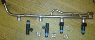
In the VAZ 2110 car, the fuel sensor is based on a rheostat with a resistor, which is made of nichrome particles. The moving element of the rheostat is lowered into the fuel and moves using a lever and a float.
The second part of the lever is, in fact, an additional contact. If you place it in a certain position, the circuit regulating the process of replenishing with spare fuel will be closed. In the domestic “ten”, the volume of reserve fuel is about 4-6.5 liters.
Alas, despite the importance of a fuel level meter, its quality is far from perfect, which is why car owners often have to deal with sensor malfunctions. It is important to note that not all breakdowns necessarily require replacement.
Sometimes you can get by with a simple tweak that will allow you to return the previous functionality to the pointer.
It is important to note that not all breakdowns necessarily require replacement. Sometimes you can get by with a simple setting that will allow you to return the previous functionality to the pointer.. https://www.youtube.com/embed/1uARg__D6HE
Typical breakdowns
Definition of marking
There are several typical malfunctions that even a beginner can cope with.
- The fuel level indicator suddenly changes its values. Most likely, the contact track has worn out due to the slider. If the wear is not severe, it is enough to simply bend the fasteners of the slider so that it is slightly above the problem area. But when wear is severe, the contact track changes completely.
- The indicator arrow is at a level that is not true. For example, it shows an empty tank even though you just filled up. This will require some adjustment. Disconnect the sensor from the gasoline tank and adjust the indicator. It is enough to move the arrow from the value at which it is stuck to zero. Most often, this measure helps.
- The arrow barely moves and cannot reach the desired position. In such a situation, the tongue bends slightly, which allows you to increase the range of the pointer arrow. It is possible that the contacts on the pointers have broken or come loose. To do this, look under the dashboard and check the condition of the wiring.
- It is possible that the fasteners securing the wires have become loose. They need to be tightened up. If the instrument panel is in good condition, examine the entire wiring path. A short circuit often occurs, causing the measuring device to stop working.
https://youtube.com/watch?v=uo_Qwbp4QKY
If all the measures taken have not yielded any result, the sensor continues to show complete inoperability, you will have to replace it.
Problems and their solutions
Old and new sample
There are several common problems typical for the dashboard of the domestically produced VAZ 2110 model.
- The instrument panel lights on the VAZ 2110 do not light up. Check the contacts and the condition of the wiring that is responsible for the suspension. The fuses could simply have blown, or the light bulbs themselves could have burned out as a result of wear and tear or a short circuit. In fact, there can be many reasons, so it is not always possible to resolve the issue in a couple of minutes.
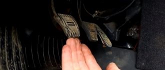
- The most serious failure for the instrument panel is a complete failure of the unit. In such a situation, all indicators stop working, the arrows fall down, and the warning lamps do not light up. To fix the problem, first check fuse 15, which is designated F6. You will find it on the mounting block. If this element is blown, simply replacing the fuse will not solve the problem. Look for the reason why it burned out. Usually this is a simple short circuit in the electrical network.
- The arrows jump up and down. This is also a common phenomenon, the cause of which in most cases is poor ground contact: This ground wire goes to the partition that separates the interior and engine compartment, from the instrument panel. To get to it, remove the radio from its seat. Check the quality of its fastening;
- Often, when installing an alarm system, the ground wire is moved to another location for more convenient access. Therefore, if you have an alarm system, but there is no wire under the radio, then look for it behind the interior trim near the driver’s left foot;
- The ground wire may be damaged when installing a new audio system. When the minus is connected, the mass is unscrewed and then often mounted back, only not as reliably as it was originally. Due to vibrations, collisions with bumps and holes, the fastening weakens and contact disappears. Hence the non-functional panel. Do not be lazy to properly wrap the bulk wire, since poor fastening is often explained by the inconvenience of performing this activity.
As practice shows, most problems associated with the failure of the dashboard can be solved independently. Especially when it comes to a car like the VAZ 2110.
But there is an important BUT. If you do not have minimal experience working with electronics and do not understand anything about electrics, we strongly do not recommend that you approach the dashboard wires. In this case, contact a service station, deal only with experienced auto mechanics and people who are well versed in automotive electricals.. https://www.youtube.com/embed/Utxc7RKfav4
Improve yourself. Perhaps soon you will be able to change to a more expensive, modern car. Then solving the electronics problem will be much more difficult. The VAZ 2110 is an excellent simulator that allows you to carry out repairs yourself, understand the structure of the car, and experience all the delights of self-repair
It is important for any man to be able not only to drive, but also, if necessary, to repair his car.
Sources
- luxvaz.ru/vaz-2110/99-ne-rabotaet-panel-priborov.html
- avtozam.com/vaz/2110/ne-rabotaet-panel-priborov-vaz2110/
- ladaautos.ru/vaz-2110/chto-delat-esli-ne-rabotaet-pribornaya-panel-vaz-2110.html
- drive2.ru/l/8812598/
Computer operation
Modern models have about 500 functions. They are all similar to each other, but in order to master the BC, you need to study the instructions that come with each device. The instructions are most intensively mastered inside the car, when the computer display is working in front of you. The most important section will be the icons and commands - you need to take them seriously, as they will inform you about the critical state of the motor and its systems.
There are usually few buttons on bookmakers, so this is unlikely to be a problem. Depending on the model you decide to install, the number of keys and functions will differ, but they can be divided into several sections:
- Those. service. Using this group, commands are created from replacing the filter or lubricant to passing the next technical inspection.
- System errors. The group is responsible for displaying errors on the display. Once you see the code, you will need to take the instructions and look it up to find out the reason.
- Diagnostic group. Here you can get information about almost all parameters, as well as the condition of the working parts and components of the car. You can also give commands to these units through the BC. For example, you can set pre-start heating - this is important in the winter season.
- Router. This includes useful data such as a black box; remaining fuel in the tank; fuel consumption in different modes; average speed.
The Orion BK-10 car on-board computer is designed for operational control of the operation of the main components of the car and is intended for installation in a standard place on VAZ 2110, VAZ 2111, VAZ 2112 cars equipped with an injection engine with electronic control units: January 5..., Bosch M1.5.4, Bosch M1.5.4N., Bosch MP 7.0 (Euro 2.3), VS 5.1 Itelma, Bosch MP 7.9.7 (Bosch 80), January 7.2, you can connect the device without installing it in a standard place on cars: VAZ 2108, VAZ 2109 , VAZ 21099, VAZ 2115, VAZ 2120, VAZ “Classic”, Niva, Chevrolet Niva, Kalina, Priora, as well as on the car The Orion BK-10 car on-board computer is designed for operational control of the operation of the main components of the car and is intended for installation in the standard place for VAZ 2110, VAZ 2111, VAZ 2112 cars equipped with an injection engine with electronic control units: January 5..., Bosch M1.5.4, Bosch M1.5.4N., Bosch MP 7.0 (Euro 2.3), VS 5.1 Itelma, Bosch MP 7.9.7 (Bosch 80), January 7.2, you can connect the device without installing it in a standard place on cars: VAZ 2108, VAZ 2109, VAZ 21099, VAZ 2115, VAZ 2120, VAZ “Classic”, Niva, Chevrolet Niva, Kalina, Priora, as well as for cars: IZH (ODA), ZAZ (Slavuta), DAEWOO (Sens) equipped with an injection engine with an electronic control unit MIKAS 7.6. The selection of blocks in VAZ cars is carried out automatically.
FEATURES The current time is always displayed on the dial. Installation and connection: — Installed in a standard place — Remote temperature sensor — Non-volatile memory Display: — Liquid crystal display — Pointer clock is constantly displayed — Russian-language interface and convenient navigation system — Super bright backlight with several stages of brightness adjustment — Regular or inverse display — Controls: - Quick call to your favorite function “Hot button” - Indication of parameters out of range
BASIC MODES 1. 1 Calendar 1. 1. 1 Calendar setting 1. 2 Clock 1. 2. 1 Clock setting 1. 2. 2 Clock adjustment 1. 3 Travel time 2. 1 Average fuel consumption 2. 2 Total fuel consumption 2. 2. 1 Fuel consumption calibration 2. 3 Instantaneous fuel consumption (l/100 km) 2. 4 Instantaneous fuel consumption (l/h) 3. 1 Average speed 3. 2 Instantaneous speed 4. 1 Trip mileage 4. 2 Mileage before maintenance 5. 1 Fuel in tank 5. 1. 1 Setting fuel after refueling 5. 1. 2 Resetting and re-setting the amount of fuel after refueling 5. 2 Mileage with remaining fuel 6. 1 Air temperature 6. 2 Temperature per day 6 2. 1 Ice warning 7. 1 Voltmeter 7. 1. 1 Overvoltage warning 7. 2 Engine temperature 7. 2. 1 Overtemperature warning 7. 3 Tachometer 8. 1 Throttle position 8. 2 Drying spark plugs 9. 1 Diagnostics - display of fault codes 9. 1. 1 Resetting fault codes 10. 1 Selecting the computer 10. 2 Adjusting the brightness of the backlight
Indication symbols
As you know, all the lights on the control panel come on when the ignition is turned on, and then, when the engine is already running, most of them go out. But when one remains on or blinks, this cannot but be alarming, because not everyone can immediately figure out what malfunctions this indicates, which of the systems needs urgent repairs.
Let's look at the designations of the instrument panel of the VAZ 2110. You should know that regardless of whether the panel is new or old on your car, the designations are almost the same, but the indicators may be located slightly differently.
Before deciding to upgrade the instrument panel, it is recommended to understand its pinout. Details: https://vazweb.ru/desyatka/elektrooborudovanie/raspinovka-paneli-priborov.html
Overvoltage protection (OVP)
BSK 6(10) kV can have a different internal design. It usually contains many low voltage capacitors connected in series. These chains are then connected in parallel to increase power. Next, groups of chains are assembled into a triangle or star to organize a three-phase system.
So, if the smallest capacitors in an accident can be under voltage of more than 110% of the nominal value, then the entire BSK is equipped with protection against overvoltage with a shutdown effect. The protection operates with a time delay.
Consider that the ZPN is mandatory because at the design stage it is difficult to understand the intricacies of the BSK design. Easier to install protection.
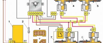
Pinout of mounting block 2113, 2114, 2115
Diagram of the VAZ-2113, 2114, 2115 mounting block Option No. 1.
K1–relay for turning on headlight cleaners; K2–relay-interrupter for direction indicators and hazard warning lights; K3 – windshield wiper relay; K4 – lamp health monitoring relay; K5 – power window relay; K6 – relay for turning on sound signals; K7 – rear window heating relay; K8 – headlight high beam relay; K9 – relay for turning on low beam headlights;
Diagram of the VAZ-2113, 2114, 2115 mounting block Option No. 2.
Numbering of plugs in the connecting blocks of the VAZ 2113, 2114, 2115 mounting block
New model mounting block VAZ-2113, 2114, 2115. Location of fuses and relays.
K1–relay for turning on headlight cleaners; K2–relay-interrupter for direction indicators and hazard warning lights; K3 – windshield wiper relay; K4 – lamp health monitoring relay; K5 – power window relay; K6 – relay for turning on sound signals; K7 – rear window heating relay; K8 – headlight high beam relay; K9 – relay for turning on low beam headlights; F1–F20—fuses; X11 – terminals of the wiring harness block
Fuse and relay block VAZ 2107
Table of circuits protected by fuses on the VAZ 2114
| Fuse number | Current strength, A | Circuits protected by a fuse |
| F1 | 20 | Rear fog lamp switching relay. Rear fog lamp lamps. Rear fog lamp switching indicator |
| F2 | 10 | Direction indicators, relay-interrupter of direction indicators and hazard warning lights (in hazard warning mode) Hazard warning lamp |
| F3 | 7.5 | Front interior lamp. Central interior lamp. Luggage compartment lighting. Illumination lamp for the ignition switch. Lamp for monitoring the engine management system. Brake light bulbs. Trip computer (if installed) |
| F4 | 20 | Socket for connecting a portable lamp. Relay for turning on the heated rear window (contacts). Rear window heating element |
| F5 | 20 | Sound signal. Horn relay. Cooling fan electric motor. Fan fuse. |
| F6 | 30 | Electric windows. Power window relay (contacts) |
| F7 | 30 | Heater electric motor. Heater fuse for VAZ 2114, VAZ 2115. Electric motor for windshield washer. Headlight wiper motors (in operating mode) Cigarette lighter fuse. Glove box lighting lamp. Rear window heating relay (winding) |
| F8 | 7.5 | Fuse for fog lamps VAZ 2114, 2115 - Right fog lamp |
| F9 | 7.5 | Fuse for fog lamps VAZ 2114, 2115 - Left fog lamp |
| F10 | 7.5 | Side light lamps on the left side. Indicator lamp for turning on the side light. License plate lamps. Engine compartment lamp Instrument lighting switch. Fuse for backlight lamps of switches, instruments, cigarette lighter, ashtray, heater control levers |
| F11 | 7,5 | Side light lamps on starboard side |
| F12 | 7,5 | Right headlight (low beam) |
| F13 | 7,5 | Left headlight (low beam) |
| F14 | 7,5 | Left headlight (high beam). High beam indicator lamp |
| F15 | 7,5 | Right headlight (high beam) |
| F16 | 15 | Direction indicators, relay-interrupter for direction indicators and hazard warning lights (in turn indication mode). Reversing lamps. Relay for monitoring the health of lamps. On-board control system display unit. Instrument cluster. Insufficient oil pressure indicator lamp. Parking brake indicator lamp (brake light fuse). Brake fluid level indicator lamp. Low battery indicator lamp. Trip computer (if installed). Generator excitation winding (in engine starting mode). Front windshield wiper. Seat heating control. |
Video text
Adapter for diagnostics ELM327 V1.5 ► https://ali.pub/2e82kw (this version is the most complete, unlike V2.1 and is suitable for a much larger number of cars with different ECUs)ELM327 - adapter for do-it-yourself diagnostics ►https: //ali.pub/3v6rfh
BI BSK VAZ (VAZ on-board control system display unit) The VAZ 2114 2113 2115 display panel and the VAZ 2110 on-board control system display unit often fail due to a breakdown of the Microswitch. Replacing the VAZ ignition switch just because of one switch is impractical.
►Restoring a 12 year old battery. RESUSCITATION. Polarity reversal and the second life of the battery https://www.youtube.com/watch?v=20e8PIrJkeA
In this video I will show my solution to the problem with the VAZ BSK, Refinement of the VAZ BSK (real-time mode) and Pinout of the BI BSK. Reworking the BSK is very simple and elementary!
The standard BSK polls all sensors ONLY when the ignition is turned on. This means that if the coolant level has dropped (the Coolant reservoir has burst or the pipe from under the clamp has leaked), the driver will not know about it until the next time he turns on the ignition, or sees the rapidly rising temperature of the Antifreeze (Antifreeze/water) Well and the “brake pad wear” indicator, also known as the VAZ 2114 pad wear sensor, monitors in real time, that is, constantly, with the ignition on.
Of course, it remains a big mystery why AvtoVAZ employees didn’t think of implementing the On-Line mode for the coolant level. After all, a brake pad sensor is present on a small number of Lada Samara cars, but a water level sensor (Coolant) is present on ALL cars.
The most common problem why the BSK VAZ 2114 does not work is the microswitch in the ignition switch. But before applying Plus forcibly (for example, from the side lights key/button), you need to make sure that fuse F16 is working properly.
The display unit of the on-board control system BI BSK 2114 is designed for installation in cars of the SAMARA and SAMARA-2 family (2108-21099 and 2113-2115) to indicate malfunctions of vehicle systems. The unit is installed in a standard location on the instrument panel and connected with the appropriate connector to the vehicle's On-Board Electrical Network (c) https://schetmash.com
BI BSK is located under the Standard BC (On-Board Computer), and in its absence - under the BC 2114 plug
BIBSK VAZ has outputs to signals from sensors:
-Relay for monitoring the health of lamps (needs modification if Diodes are used in Dimensions) -Door limit sensor -Oil level sensor -Coolant level sensor -Washer fluid level sensor -Seat belt sensor (unfastened belt sensor) -Brake sensor (pad wear sensor) - Driver door opening sensor (limit switch)
BSK VAZ 2113 2114 2115. BI BSK does not work. Revision + online___________________________
Basic designations of icons on the VAZ instrument panel
The presence of icons on the dashboard plays one of the most important roles while driving a car. They are responsible not only for navigation through the vehicle systems, but also promptly inform about the occurrence of any malfunctions, breakdowns or improper operation of the vehicle. That is why every car enthusiast needs to know the location, interpretation and designation of icons on the VAZ instrument panel.
If one or another indicator suddenly appears on the dashboard, you will be able to react in time, which will save you from getting into a difficult situation. Often the indicators only serve as a kind of alarm, but when they go off, it is best to immediately go to the garage for repairs or seek help from a car service center.
DISTINCTIVE FEATURES OF BSK UKKZ LLP:
- certification of BSK in JSC FGC UES;
- relatively low cost and quick payback;
- extensive experience in the manufacture of capacitors and power capacitor equipment;
- own production base for the production of capacitors;
- quick installation and ease of operation;
- development of BSK according to customer requirements;
- the possibility of using BSK as part of filter-compensating devices, static thyristor compensators.
Installing an on-board computer on a VAZ 2110 with detailed instructions
Each standard on-board computer on the VAZ 2110 comes with instructions, according to which you can dismantle the old computer and put a new one in its place. Therefore, first of all, arm yourself with this guide.
It’s not difficult to figure out for yourself how to connect an on-board computer to a domestically produced VAZ 2110 car. It is necessary to act consistently and follow stages.
- First, remove the terminal that comes from the battery.
- Find the alarm block and remove it. The on-board computer is connected to it.
- The orange wire should be removed from the seventh contact.
- In its place, a red and white wiring is attached, which is pulled from the on-board computer harness.
- Disconnect the orange wire and install it in the connector from which you previously removed the wire.
- The red wire with black stripes will be disconnected from the tenth contact. The red wire from the BC harness is attached here. Instead of red, connect red-black. Essentially, you are swapping wires.
- Disconnect the black wire from the fifth contact. A wire of the same black color from the on-board computer harness is connected to it. This is a very important point, don't miss it.
- The black wire from the block is connected here.
- Now it’s the turn of the eighth contact. The white wire is removed from it, and the white wire from the harness is connected in its place. That is, a change of places occurs again.
- Make sure there is contact between the wires.
- Check the quality of fixation of each disconnected and connected wiring. Use insulating tape in areas where they are curled.
- The harness is pulled through the internal section of the console to the site for subsequent installation of the on-board computer.
- Next, you should carefully and firmly connect it to the sensor, which is responsible for adjusting the fuel level in the car.
- Remove the instrument panel to give yourself access to the gray block.
- Disconnect the fuse box. It is located to the left of the driver.
- From the gray block, remove the pink wire that transmits the signal to the fuel level sensor. The pink wire from the harness of your on-board computer is connected to it.
- Install the sideboard in its rightful place.
- Reconnect the battery terminal to turn the ignition on. Start the engine and check if everything works on the installed on-board computer.
By following fairly simple instructions, you should be able to connect the VAZ 2110 BK to your car without any problems. Carefully study each point, think about whether you can really do everything yourself.
As we have already noted, the approximate cost of a new on-board computer intended for installation on a VAZ 2110 car is 2 thousand rubles. There is no need to purchase additional tools or materials for self-installation, that is, the whole process will cost you 2 thousand.
When you contact a service station, you will be asked for about 2 thousand rubles more to connect the on-board computer. This is the best case scenario.
Considering the relative simplicity of the work, there is no need to trust it to car mechanics. By consistently performing each step and following the instructions, you will be able to equip your VAZ 2110 with an on-board computer with your own hands.
Installation specifics
Table of characteristics of a digital voltmeter.
If there are no problems during installation with digital voltmeters that are powered from the cigarette lighter, then models installed directly into the dashboard often force drivers to think about the order in which they are connected.
Most voltmeters on the market have two or three wires for connecting to the network, although there are models with four contacts. The wires have standard color markings:
- the red wire corresponds to “plus”;
- the black wire is connected to the negative;
- The white wire is responsible for controlling the backlight intensity and turning the device on and off.
In some cases, an unexpected problem arises when connecting the voltmeter in this way: it lights up dimly or refuses to work at all. The reason may be the alternative marking of the wires, in which the white wire is responsible for the “minus”, and the black wire for controlling the device.
The voltage sensor is installed in the standard place of the clock, but in some cases, when it is impossible to find free space for the voltmeter, you have to make a hole for it directly in the dashboard.
An excellent place to connect the device is the dashboard plug on the left side of the steering wheel. It is small in size and easy to remove and secure for processing.
Figure 1. Connection diagram for a voltmeter with a pulse stabilizer.
The voltmeter body has a raised surface: the frame around the display will protrude above the surface of the car panel. Thanks to this, the device will not fall inside the mounting socket, and will also hide uneven edges of the hole.
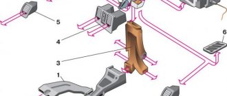
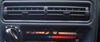
Additional panel
The additional front panel of the new-style BSK control has indicators:
- An oil can is shown. If the light works, check the oil level;
- An icon lights up, which, with some imagination, can be “identified” as working wipers. This indicates that there is not enough windshield washer fluid in the tank;
- Conventional image of a thermometer over a container with liquid - high temperature of antifreeze;
- A crossed out light, which the arrow points to, is a sign that the brake light or parking lights are not working;
- If the light with the image of a wheel with brake pads lights up, it is quite possible that the pads are worn out and require replacement;
- The sign of a man with a seat belt indicates that the seat belt should be fastened.
Reworking the low beam button
As already mentioned, the button for turning on the low beam and the button for the dimensions of the VAZ 2114 are combined and located in pairs. Their main drawback, which most car enthusiasts point out, is the absence of a power-on LED on the low-beam headlight button.
This problem is quite serious, since very often it becomes unclear whether the headlights are working or not (especially during daylight hours). You can solve this by upgrading the button yourself.
For this you will need:
- a button that will be redesigned;
- the second button is the same - donor;
- soldering iron or (better) soldering station.
The button modification should be carried out according to the diagram shown here. Resoldering the LED itself from one board to another is highly not recommended, since this requires a soldering station equipped with a hair dryer, a special flux and high skill in working with them.
First, we need to remove the main button from the car panel (how to do this has already been discussed above).
After it is removed and disconnected from the wires, perform the following operations:
- remove the keys by prying them off with a flat screwdriver;
- we disassemble the body of the buttons by pressing the latches with a screwdriver (the buttons themselves at this moment must be in the “on” position);
- we see that the sidebar button has two diodes (backlight and indication), and the low headlight button has only a backlight button;
- remove a pair of legs and a pair of contacts from the donor button;
- we rearrange them into the free spaces on the working button;
- remove the board from the donor button with two diodes and insert it into the working button instead of the board with one diode;
- solder the board to the legs that were added;
- make a hole in the button cover (this can be done with a sharp knife or simply punched with a flat screwdriver).
The junction of the newly installed legs and the new board must be well soldered. Otherwise, the button may quickly fail or not work correctly.
After all these operations have been completed, all that remains is to assemble everything in the reverse order and install the upgraded button in its place (during installation, it is important that all the mini-latches on the case fall into place)
The meaning and location of the main instruments on the VAZ panel
The combinations of all instruments on the most popular brand (VAZ-2110) are located directly on the left side of the panel itself. This part of the dashboard is often called a “dashboard” by drivers. The instrument panel also contains switches of various functions and types and a set of indicator lights. They are responsible for controlling the operation of lighting equipment, heaters and other important units.
Standard instrument panel on a VAZ-2110 car
First of all, when examining the dashboard, the eye falls on the variety of dial gauges and indicators under them, which are equipped with a small electronic digital window and a set of signal lights with various functions. The main elements here are:
- Sample induction speedometer;
- Tachometer model;
- Pointer type indicator for adjusting the coolant temperature;
- A device for determining the fuel level in the tank.
Let's look at each of the devices in more detail.
Tip: if light bulbs, indicators and dial gauges do not work, then the problem lies in the wiring. Be sure to check the fuse box on the VAZ-2110.
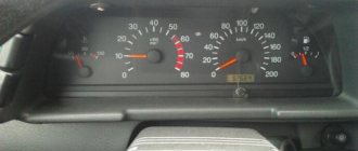
Symbols in the induction speedometer
Models of induction speedometers receive speed readings from sensors that are located directly in the gearbox structure. It displays the actual speed of the car - the scale ranges from 0 to 200 km/h.
The division value is an indication of 10 km/h. However, the driver must remember that any induction speedometer on the VAZ-2110 will have an acceptable error rate of up to 3-5 km/h.
The lower and central part of the speedometer is equipped with a small window with an electronic display option, which, through 2 lines, transmits the total mileage for the entire period of operation of the vehicle and the current mileage value.
Tachometer symbols
The tachometer is located on the left side of the dashboard. Using this device, the driver receives the current crankshaft speed values. Information enters the tachometer through the on-board computer, which in turn receives these values from sensors on the crankshaft. Often, if the car jerks when you sharply press the gas. The tachometer will show low speed values or will be completely faulty.
On the scale, all divisions are divided into 5 units, and the digitization of values is made into 10 units. The maximum values are limited to 80 units. In order to understand what number of revolutions the car is currently showing, you need to multiply the number on the tachometer by 100. The sector is in the range from 55 to 60 units. shaded in red - this is a signal to the driver that the car will be approaching a critical number of revolutions.
Advice:
When the crankshaft speed approaches the red sector, a sudden stop and engine failure may occur.
The lower middle part of the device, using an electronic display, displays the real temperature of the air surrounding the car and the time.
Designations on the coolant temperature dial gauge
On the left side of the tachometer there is a universal dial indicator that regulates the temperature in the coolant. The device receives signals about current indicators from the corresponding coolant temperature indicator, which is located next to the cylinder head and thermostat structure.
Here, the division value is considered to be 20 degrees, and the general digitization indicators start at a value of 50 units. and end with a division of 130 degrees. The dangerous zone of the device operation is highlighted in red, which starts at a value of 105 degrees. If the instrument needle begins to fall into this zone, the VAZ-2110 engine must be immediately turned off and the car stopped.
If the engine overheats, not only the main set of power unit units may fail, but also the fan switch sensor, as on the VAZ-2107.
Designations in the fuel gauge in the tank
To the right of the speedometer there is an indicator showing the level and general availability of gasoline in the fuel tank of your vehicle. It works using a sensor in the tank, and sends data through the on-board computer to the scale. The indicators of the dial gauge have the following designations:
- 0 - your tank is completely empty (the machine will be able to work for another 15-20 minutes).
- ½ - there is still half a tank of gasoline in the car.
- 1 - the car is filled with a full tank.
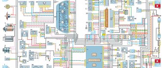
Which wire goes where?
First, let's look at the back of the instrument panel. At the top there are:
- fuel level indicator;
- dashboard lighting lamps;
- control of right and left turns (separately);
- tachometer;
- block with many plugs;
- coolant temperature gauge.
As you can see, there is really nothing particularly complicated here. At the bottom of the instrument panel on the back side there are controllers:
- high beam;
- "emergency lights";
- CHECK ENGINE;
- battery charge;
- parking brake;
- oil pressure;
- air damper (for models with a carburetor);
- outdoor lighting work.
In addition, there is also a speedometer and a brake fluid level indicator lamp.
Now let's take a closer look at the pads. There are two of them - white and red. In the first, the connectors and wires look like this (in order):
- Ground wire black.
- Red-brown – low-voltage supply from the ECU to the tachometer.
- Yellow – high-voltage supply to the tachometer from the coil.
- Red-blue - comes from the battery through the 6th fuse Const with a voltage of 12 volts.
- Green-white - leads to the coolant temperature sensor.
- Green-yellow – fuse F1, responsible for the side lights.
- This connector has no color, it goes to the throttle valve.
- Red and white – leading to the CHECK ENGINE indicator light.
- 2 orange wires leading to two F19 + 12 volt power fuses.
- Same as the previous connector.
- 2 blue-brown wires leading to the “VK” terminal of the handbrake.
- The output to terminal D of the generator is a brown-white wire.
- Gray and blue - wire going to the oil pressure sensor.
In the red block, the connector number according to the account, the color of the wires and the devices to which they lead are as follows:
- Red-blue – leads to the external temperature sensor.
- Orange – goes to power fuse F19 + 12 volts.
- 2 black ground wires.
- White – leads to the instrument lighting switch.
- Blue – to the right turn indicator.
- Blue-black - to the left turn indicator.
- Blue-pink - to the brake fluid level sensor.
- Brown – leads to the on-board computer.
- Gray - to the speedometer.
- Pink – to the fuel level indicator.
- 2 green-black wires leading to fuse F3, which is responsible for the high beam.
- Blue-white - to the hazard warning switch.
- The white wire leads to terminal 50 - the ignition switch.
It is worth especially noting here that the most typical and common pinout diagram is shown above. However, different manufacturers may have differences in color markings. For example, in the instrument panel manufactured by the Kursk "Schetmash" there will be minor differences from the above diagram, in particular in the red block (connector number and wire color):
- black;
- red-brown;
- yellow;
- red and white;
- green-white;
- 2 brown wires;
- empty;
- red and white;
- blue;
- orange;
- blue-brown;
- white-brown;
- blue-gray.
As you can see, there are still certain differences, even if they are small.
However, these little things are very important. Therefore, it is best, before starting work, to find out which panel your car has (by year of manufacture and manufacturer), and then find the correct pinout diagram. However, there is another option - the self-adhesive pieces of paper already mentioned above.
When disconnecting the wires, be sure to label them - this will greatly facilitate the assembly process.
However, there is another option - the self-adhesive pieces of paper already mentioned above. When disconnecting the wires, be sure to label them - this will greatly facilitate the assembly process.
What standard trip computers exist?
Option 2. Installed instead of a small plug next to the ACS unit
These were installed on “luxury” dozens. There are models AMK 211000 without diagnostics, and AMK 211001, AMK 211002 with diagnostics. You can find out which one you have by looking at the numbers on the back cover. To do this, naturally, the MK must be removed. If on the back there are the inscriptions AMK-211001 or AMK 211002, and in clock mode, when you press the “clock” button, the inscriptions Err appear and then two more - great. You have a full-fledged bookmaker.
If these are the inscriptions:
Unfortunately, this is a BC that either lacks diagnostic capabilities or has “cut-off” firmware.” Craftsmen resolder and reflash such models, but in my opinion they are not worth it.
It is very easy to remove such a MK. Disconnect the negative cable terminal from the battery terminal. We pry it off with a screwdriver...
remove the MK from its seat....
....disconnect the wire block from it.
Checking the BSK in minimum mode
Next, you need to check whether using the BSC in the minimum mode will not lead to exceeding the maximum permissible voltage value. The load curve unevenness coefficient is assumed to be 0.6.
According to the calculation results, the voltage in the node under consideration was 10.77 kV, which is within acceptable limits. Based on this, we can conclude that turning off the BSC in minimum load mode is not required.
Network calculations in PC RastrWin3 in minimal mode are given in this file.
Indicators
Dashboard
At the moment of ignition, all the lights on the instrument panel light up; after the engine starts, most of the indicators go out. Sometimes, even after starting the engine, one light continues to glow or even blink. This alarms drivers, because it is difficult to say which component in a VAZ 2110 car is malfunctioning; diagnostics are required to determine the breakdown.
At the bottom of the instrument panel there are indicators that indicate a malfunction in the operation of various systems of the VAZ 2110. If they continue to light when the engine is running, it means that repairs will have to be carried out.
We go from left to right:
- The leftmost light, located on the instrument panel, refers to the air damper - the indicator is present in models with a carburetor engine;
- Oil can icon. If the indicator lights up or flashes, it means that the oil compression in the power unit has dropped and the pump is not working properly;
- The letter "P" inside a circle. The dashboard tells you that you forgot to turn off the parking brake;
- A light indicating a faulty battery or generator. Perhaps the alternator belt has broken, there is an open circuit in the circuit, charging is not performed;
- When the “high beam” is working, the headlight icon lights up on the panel;
- On light bulb icon – the indicator shows the lights on;
- "Check Engine" indicator. If it burns, then it is urgent to carry out diagnostics and subsequent repair of the VAZ 2110 engine; serious defects have appeared in the operation of the power plant. The best solution is to stop moving;
- Directly above the faulty engine sign is a warning light.
In addition to these indicators, the front part is equipped with a display showing mileage. Also in this area are the clock and setting keys for it. In the “tens” of the new generation, the screen may be of a narrow format, but the layout remains the same.
Additional panel
New cars have an additional panel with useful indicators. A flashing icon depicting a person with a seatbelt informs you that you should fasten your seat belt - this applies to both the driver and his companions. While driving, the wheel icon may light up; there is a possibility that the pads are worn out and require repair.
- Oil light - lights up when the oil level drops below normal - you should check the level as soon as possible.
- Windshield washer - it tells us that the washer fluid is almost empty.
- The thermometer above the container indicates an increased temperature of the coolant.
- A crossed out arrow icon means the parking or brake lights are not working.