As you remember, last time we looked at how to replace the timing chain and sprockets with new ones. However, before installing the valve cover in place, it is necessary to adjust the thermal clearance in the valve drive. Today we will analyze this moment.
The gap is adjusted after work involving intervention in the gas distribution mechanism, when a loud knocking occurs on a warm engine, and also every 10 thousand kilometers (according to the operating manual). Before work, you need to check and adjust the chain tension, which we did earlier. The adjustment is carried out with a flat, wide feeler gauge 0.15 mm thick or an adjusting rod at an engine temperature of 20 C°, however, it can also be done at a different temperature by making the necessary adjustment.
| The release can be ignored |
However, it should be borne in mind that then you will need a set of probes of various thicknesses.
Rack adjustment is considered the most accurate for setting the clearance, even with significant wear on the camshaft and valve levers (rockers). Using a feeler gauge to set the correct gap on parts even with low production is already problematic, but this option is simpler and more accessible in garage conditions. So, we will need:
- socket wrenches “8”, “10”
- wrenches “13”, “17”
- flat screwdriver
- special wrench or socket for the crankshaft nut (ratchet)
- probe 0.15 mm
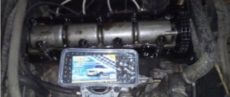
Before starting work, you must turn off the engine and allow it to cool to the required temperature. Remove the cylinder head cover, having first removed or moved aside the interfering pipes and filters.
Now you need to install the crankshaft and camshaft to the position of the top dead center of the 4th cylinder (TDC), aligning the factory marks on the crankshaft pulley and camshaft sprocket with the corresponding ebb marks on the engine body.
This can be done using a special wrench (or socket), turning the crankshaft by the nut clockwise.
Or by jacking up the rear wheel and spinning it in 4th gear, we ensure that the marks match.
To make work easier, you can unscrew the spark plugs and remove the alternator belt. So, in this position we can adjust the thermal clearance on the 8 and 6 valves. Sequential numbering starts from the camshaft sprocket.
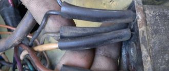
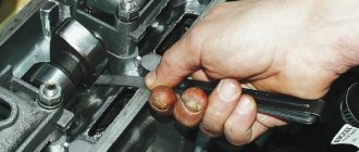
To do this, insert the dipstick into the gap between the rocker and the camshaft cam. If it fits quite freely without noticeable resistance or, conversely, when it “bites”, it is necessary to make an adjustment: use a “17” wrench to loosen the lock nut of the adjusting bolt and use a “13” wrench to tighten or unscrew the bolt, having achieved the required clearance, tighten the lock nut back.
When tightening the locknut, you must keep in mind that the gap will decrease slightly, so an adjustment should be made. It is unlikely that you will be able to select the gap the first time - as a rule, this comes with skill.
After adjustment, the probe should enter with noticeable force, bend a little, but not “bite”. Consistently turning the crankshaft 180° (camshaft 90°), we check and adjust the clearances of the next pair, observing the order.
To make adjustment work easier, additional marks can be applied to the crankshaft pulley and camshaft sprocket.
After the adjustment is completed, the crankshaft should make almost two revolutions, and the camshaft should make almost one revolution. We check again the tightness of all locknuts. To be on the safe side, you can crank the crankshaft and check the clearances again.
Reinstall the removed parts in reverse order.
Subscribe to the blog! Good luck on the roads!
Source: https://autovazremont.blogspot.com/2018/02/regulirovka-zazora-klapanov-vaz-2107.html
Adjustment of valves
If knocking, unstable operation, or increased vibration occur, you should pay attention to the valves.
If the valve timing of the gas distribution mechanism is disrupted, they do not operate accurately, that is, the full volume of gas does not enter the working area of the cylinders, complete combustion of the fuel-air mixture in the working chamber does not occur, and the cylinders are not purged. This is all accompanied by the appearance of a shock load on the camshaft cams on the drive lever and the shaft rod. Fuel and engine oil consumption also increases. What happens if you drive with unadjusted valves? Answer: rapid wear of engine parts, increasing cost and repair time.
Rubber oil deflectors, also known as oil deflectors, also burn out due to a burnt valve cap, which leads to increased engine oil consumption. If the wear of engine parts is large, then it may be better and easier to do an engine swap with your own hands or at a service station.
Even if your engine does not have a belt drive, but a chain drive, then if you do not change the chain before its service life expires, the valves will bend on the piston, as, for example, in the sr20det engine manufactured by Nissan.
Adjustment with a micrometer
The most accurate method for regulating valve thermal clearances is to use a device with a dial indicator - a micrometer. A micrometer is a very sensitive device that responds to changes in the translational movement of its measuring rod every hundredth of a millimeter.
The procedure is similar to the order of adjustment using a feeler gauge. The peculiarity of this method is to install a rail on the studs of the camshaft bed, onto which a micrometer is attached. The rack contains information on the angles of the crankshaft position to the valves corresponding to adjustment.
Before starting work, the micrometer is mounted on a device that has a lever in the form of a rocker arm. One side of the lever rests on the micrometer rod with a light touch, and the other on the extreme part of the rocker. By lifting the rocker without force with a special “spade” until it touches the back side of the camshaft cam, note how many divisions the arrow has deviated from the zero position. For a carburetor engine, the needle should deviate by 52 divisions.
A micrometer for adjusting valves is supplied with a description and all necessary accessories.
A homemade rail can be made according to a factory design. With the help of such a rack, the actions when independently adjusting the valves are more confident and there is no need to remember the routine or sequence of operations.
The procedure for adjusting valves VAZ 2101-2107
First we prepare the car:
- wait until the engine cools down if it was running;
- park the car on level ground;
Valve adjustment procedure:
- Remove the air filter cover and the filter itself.
- Remove the air damper control cable (choke).
- Remove the throttle linkage.
- Unscrew the nuts securing the valve cover and remove it.
- Before adjusting the valves, immediately check how the chain is tensioned. If the tension is not normal, you will have to do the work again.
- Remove the distributor cover.
- We install the piston in the 4th cylinder at top dead center (TDC). TDCs are set using marks on the internal combustion engine crankshaft pulley and the camshaft drive cover, and marks are also applied to the camshaft gears and camshaft cover. The mark is set with a special key for the internal combustion engine crankshaft pulley bolt. If you don’t have a key, you can set the 4th piston to TDC by rotating one of the rear wheels. Raise one side with a jack and place the gear shift lever in 4th gear to make it easier to turn and turn the wheel slowly. When setting marks without a key, you will need an assistant to look at the marks.
- When the marks on the camshaft and the camshaft cover are aligned, check that the marks on the crankshaft are also aligned. You can also check whether the marks on the distributor slider match. The contact terminal should be directed to the high voltage wire terminal of the fourth cylinder. We have already discussed how to determine whether ignition is early or late in another article.
- After the marks match, we proceed to adjusting the valve clearances.
The correct procedure for adjusting the valve mechanism of the VAZ “Classic” 2101-2107. Crank angle Adjustable valves 8 and 6 180 4 and 7 360 1 and 3 540 5 and 2
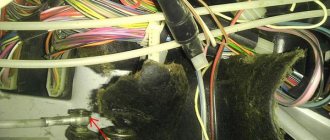
Disconnect the filter mounting tubes and remove the mount.
From the table we see that if the 4th piston is set to top dead center, then we measure and adjust the 6th and 8th valves.
Adjustment order table:
On a carburetor engine, to more accurately determine the position of the camshaft, it is possible to use a distributor, the slider of which is directed to the socket of the high-voltage wire of the corresponding cylinder. If the distributor cover is removed, then four screws on the housing that coincide with the sockets of the high-voltage wires can serve as a guide.
You can also use the distributor with the cover removed: connect a control light to the low-voltage circuit and turn the crankshaft with the ignition on. The moment the light turns on indicates the exact position of the camshaft at which the corresponding pair of valves is adjusted.
Adjusting valves on VAZ 2101-VAZ 2107
Welcome! Valve adjustment is currently an integral part of all engines that do not have hydraulic compensators. What are hydraulic compensators? In short, thanks to them, the valves open and close with the most even gap, and therefore the valves no longer need periodic adjustment, and their smooth stroke is also created, thanks to which the engine runs quieter and softer. But today we will not talk about hydraulic compensators, but about valve adjustments on cars of the “Classic” family.
Note! To adjust, you will need the following tools: First, stock up on a basic set of wrenches, and you will also need screwdrivers, a flat feeler gauge for adjusting valves with a thickness of “0.15 mm” and finally, you will need to stock up on a special wrench for turning the crankshaft! (If there is no special key, then in this case you can use a “36” head instead)
Summary:
When should valves be adjusted? Valves require adjustment when:
- If a knock appears in the area where the valves are located, the knock can only be heard when the car engine is running.
- And so they must be adjusted after work, during which the camshaft was removed from the car.
Note! As a note, keep in mind one important detail: when operating a car, the valves develop gaps over time, which do not lead to emergency engine breakdowns, but only disrupt its operation, as a result of which the parts of the valve mechanism will wear out faster!
Puller drawings. Repair equipment. Tool
Device for tensioning the timing belt (for a new type of roller).
The device is a metal, slightly curved strip, 2 - 3 mm thick, 120 mm long. and width - 25 mm. On one side at a distance of 10 mm. two pins with a diameter of 4 mm are installed from the end. The height of the pins is 10 mm, the distance between the pins is 17 mm. The diameter of the semicircle is 16 mm. Everything should be clear from the photograph of the device.
Instead of this device, to tension the timing belt, you can use two drills (4 mm in diameter) inserted into the holes of the tension roller. We insert a screwdriver between the drills and use it as a lever to tighten the timing belt.
Device for adjusting valves.
Due to the relative complexity of this device and its low cost (less than 200 rubles), I recommend just buying it.
As a last resort, you can use a pair of regular flathead screwdrivers. Using one powerful screwdriver, we recess the pusher, and with the second (you can bend it a little and sharpen it in place) we fix the pusher by the side. But this method is extremely inconvenient and the fixing screwdriver can fly out; in general, it’s only suitable as a last resort.
How to adjust valves on a VAZ 2101-2107?
1) First, remove the cylinder head cover. (For information on how to remove the cylinder head cover, read the article, “Setting the valve timing by marks,” in the “ removal ” section, from point 1-10)
2) Then set the piston of the fourth cylinder to the TDC position. (For information on how to install the piston of the fourth cylinder to the TDC position, see the article “Installing the piston of the fourth cylinder to the TDC position”)
3) Then adjust the “eighth and sixth” valves, but before you start adjusting them, check if they need adjustment, to do this:
1. Insert the feeler gauge into the valve gap and see how it moves there.
Note! When you insert the feeler gauge into the gap, it should move there with little difficulty, but if it moves smoothly in and out of the gap, then the valve needs adjustment!
4) If the valves need adjustment, then:
1. Insert the probe into the “sixth or eighth” valve and then use the key indicated under the letter “B” to loosen the lock nut.
2. At the same time, use another wrench to set the valve gap you need by unscrewing or tightening the adjusting bolt, which is marked with the letter “A”.
3. And to complete the operation, tighten the bolt indicated under the letter “B”.
5) Next, read the section “Sequence of valve adjustment” just below, and adjust all the remaining valves on your car.
In what order should the valves be adjusted?
Note! Before you start studying, remember one thing that will be indicated in the instructions, namely, it will say that the crankshaft will need to be turned “180°”, which means half a turn! (The crankshaft revolutions are easy to understand by following the mark on the camshaft)
1) You should start adjusting the valves:
1. First from the “sixth and eighth” valves.
2. Then you will need to turn the crankshaft clockwise, exactly 180° and then begin adjusting the “fourth and seventh” valves.
3. Next, again turn the crankshaft 180° clockwise, and this time adjust the “first and third” valves.
4. And to complete the work, turn the crankshaft 180° clockwise again, and then adjust the “second and fifth” valve.
Important! 1) Do not disturb the order of valve adjustment! 2) The valves need to be adjusted only on a cold engine!
For newbies! Question: What does the gap adjustment feeler look like? Note: The photo shows two types of probes!
Additional video clip: Especially for you, we have prepared an interesting video clip, after watching it, most of your questions about valve adjustment will most likely disappear, but if you still have questions, then ask them in the comments and we will answer them for you.
Source
Purpose and design of the valve mechanism of the VAZ 2101
The operation of an internal combustion engine is impossible without a gas distribution mechanism (GDM), which ensures timely filling of the cylinders with the fuel-air mixture and removes its combustion products. To do this, each cylinder has two valves, the first of which is intended for the intake of the mixture, and the second for the release of exhaust gases. The valves are controlled by camshaft cams.
The camshaft is driven by the crankshaft via a chain or belt drive. Thus, the piston system ensures time-distributed intake and exhaust of gases in compliance with the sequence of valve timing. The rounded tips of the camshaft cams press on the rocker arms (levers, rockers), which, in turn, actuate the valve mechanism. Each valve is controlled by its own cam, opening and closing it in strict accordance with the valve timing. The valves are closed using springs.
The valve consists of a rod (rod, neck) and a cap with a flat surface (plate, head) covering the combustion chamber. The rod moves along a sleeve that guides its movement. The entire timing belt is lubricated with engine oil. To prevent lubricant from entering the combustion chambers, oil seals are provided.
Each valve timing must strictly correspond to the position of the pistons in the cylinders. Therefore, the crankshaft and camshaft are rigidly connected through the drive, with the first shaft rotating exactly twice as fast as the second. The full operating cycle of the engine consists of four phases (cycles):
- Inlet. Moving down in the cylinder, the piston creates a vacuum above itself. At the same time, the intake valve opens and the fuel-air mixture (FA) enters the combustion chamber under low pressure. When the piston reaches bottom dead center (BDC), the intake valve begins to close. During this stroke, the crankshaft rotates 180°.
- Compression. Having reached BDC, the piston changes direction of movement. As it rises, it compresses the fuel assembly and creates high pressure in the cylinder (8.5–11 atm in gasoline engines and 15–16 atm in diesel engines). In this case, the inlet and outlet valves are closed. As a result, the piston reaches top dead center (TDC). In two strokes, the crankshaft made one revolution, that is, it rotated 360°.
- Working progress. A spark ignites the fuel assembly, and under the pressure of the resulting gas, the piston is directed to BDC. During this phase the valves are also closed. Since the beginning of the working cycle, the crankshaft has rotated 540°.
- Release. Having passed BDC, the piston begins to move upward, compressing the gaseous combustion products of the fuel assembly. At the same time, the exhaust valve opens, and under the pressure of the piston, gases are removed from the combustion chamber. In four strokes, the crankshaft made two revolutions (rotated 720°).
The gear ratio between the crankshaft and camshaft is 2:1. Therefore, during the operating cycle the camshaft makes one full revolution.
The timing belts of modern engines differ in the following parameters:
- upper or lower location of the camshaft;
- number of camshafts - one (SOHC) or two (DOHC) shafts;
- number of valves in one cylinder (from 2 to 5);
- type of drive from the crankshaft to the camshaft (toothed belt, chain or gear).
The first carburetor engine of VAZ models produced from 1970 to 1980 has four cylinders with a total volume of 1.2 liters and a power of 60 hp. With. and is a classic in-line four-stroke power unit. Its valve train consists of eight valves (two for each cylinder). Unpretentiousness and reliability in operation allows it to use AI-76 gasoline.
Video: operation of the gas distribution mechanism
Gas distribution mechanism VAZ 2101
The gas distribution mechanism of the VAZ 2101 is driven by the crankshaft, and the camshaft is responsible for the operation of the valves.
The torque from the engine crankshaft (1) through the drive sprocket (2), chain (3) and driven sprocket (6) is transmitted to the camshaft (7), located in the cylinder head (cylinder head). The camshaft lobes periodically act on the drive arms or rockers (8), driving the valves (9). Thermal clearances of the valves are set by adjusting bolts (11) located in the bushings (10). Reliable operation of the chain drive is ensured by the bushing (4) and the adjusting unit (5), the tensioner, and the damper (12).
The power strokes in the cylinders of the VAZ 2101 engine have a certain sequence.
Main malfunctions of the VAZ 2101 timing belt
According to statistics, every fifth engine malfunction occurs in the gas distribution mechanism. Sometimes different faults have similar symptoms, so a lot of time is spent on diagnosis and repair. The following are the most common causes of timing belt failure.
- Incorrectly set thermal gap between rockers (levers, rocker arms) and camshaft cams. This results in incomplete opening or closing of the valves. During operation, the valve mechanism heats up, the metal expands, and the valve stems elongate. If the thermal gap is set incorrectly, the engine will have difficulty starting and will begin to lose power, popping noises will appear from the muffler and a knocking noise will appear in the engine area. This malfunction is eliminated by adjusting the gap or replacing the valves and camshaft if they are worn.
- Worn valve stem seals, valve stems or guide bushings. The consequence of this will be an increase in engine oil consumption and the appearance of smoke from the exhaust pipe during idling or acceleration. The malfunction is eliminated by replacing the caps, valves and repairing the cylinder head.
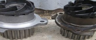
- Failure of the camshaft drive as a result of a weakened or broken chain, breakdown of the tensioner or chain guide, wear of the sprockets. As a result, the valve timing will be disrupted, the valves will freeze, and the engine will stall. It will require a major overhaul with the replacement of all failed parts.
After eliminating any of the malfunctions of the VAZ 2101 engine, it will be necessary to adjust the gap between the rockers and the camshaft cams.
Video: the influence of thermal valve clearance on timing belt operation
Consequences of untimely adjustment
Untimely maintenance of the gas distribution mechanism negatively affects engine performance, causing unbalanced operation. The engine runs rough, there is no traction performance, and fuel consumption increases. It is known that the injection phase is directly dependent on the thermal clearance of the valves. Correct and correct adjustment allows the valves to open and close in a timely manner. If the gap is set less than the permissible value, then the valve begins its operation with some advance, and vice versa, if the gap is large, it opens late. Reduced clearance on exhaust (hot) valves increases the time they remain open, which can cause the edges to slowly burn out, leading to loss of compression in the cylinder.
When operating the engine on gas (propane or methane), the thermal clearances must be adjusted with the same gaps, the value of which is determined by the instructions for operating the engine on gasoline. Adjusting the valves for gas does not have scientific and technical validity and can lead to unstable engine operation.
Source
Dismantling and repair of the cylinder head of the VAZ 2101
To replace valve mechanisms and guide bushings, you will need to dismantle the cylinder head. This operation is quite labor-intensive and painstaking, requiring certain metalworking skills. To perform this you will need the following tools:
- a set of wrenches (heads 8, 10, 13, 17, 19 are required);
- slotted and Phillips screwdrivers;
- pliers;
- mandrels for pressing out and pressing in guide bushings;
- device A.60311/R for removing valve springs (depressurizer);
- puller and mandrel for oil seals;
- torque wrench.
Before dismantling the cylinder head, you must:
- Drain antifreeze from the engine cooling system.
- Remove the air filter and carburetor, first disconnecting all pipes and hoses.
- Disconnect the wires, unscrew the spark plugs and antifreeze temperature sensor.
- After unscrewing the fastening nuts with a size 10 wrench, remove the valve cover along with the old gasket.
Replacing valve springs and oil seals
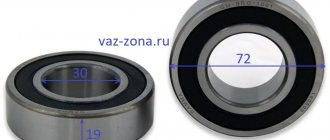
Support bearings, camshaft, springs and oil seals can be replaced without removing the cylinder head. To do this, you will need a device for extracting (loosening) the valve springs. First, the specified elements are replaced on the valves of the first and fourth cylinders, which are at TDC. Then the crankshaft is turned by a crooked starter 180°, and the operation is repeated for the valves of the second and third cylinders. All actions are performed in a strictly defined sequence.
- A soft metal rod with a diameter of about 8 mm is inserted into the spark plug hole between the piston and the valve. You can use tin solder, copper, bronze, brass, or, in extreme cases, a Phillips screwdriver.
If no other repair work is required, the timing belt is assembled in the reverse order. After this, it is necessary to adjust the thermal clearance of the valves.
Replacement and grinding of valves, installation of new guide bushings
If the valve caps are burnt out, or a coating of impurities in oil and fuel has formed on them, preventing a tight fit to the seats, the valves must be replaced. This will require dismantling the cylinder head, that is, you will need to complete all the points of the above algorithm before installing new oil seals on the valve necks. The caps and springs themselves can be installed on the removed cylinder head after replacing and grinding in the valves. The work is performed in the following order.
- The hoses are disconnected from the carburetor, the inlet pipe and the outlet pipe of the cylinder head cooling jacket.
- The starter protective shield and the exhaust pipe of the mufflers are disconnected from the exhaust manifold.
- The oil pressure sensor is disconnected.
- The bolts securing the cylinder head to the cylinder block are broken off and then unscrewed with a wrench and ratchet. The cylinder head is removed.
- If the valve mechanisms have not been disassembled, they are removed in accordance with the instructions given above (see “Replacing valve springs and valve stem seals”).
Video: repair of cylinder head VAZ 2101–07
Getting started and disassembling
Before starting work related to adjusting the thermal clearances of the valves, it is necessary to prepare the engine, tools and related materials.
Secure the car with the handbrake and move the gearbox to neutral. For safety reasons and to prevent independent movement, additionally install shoes under the wheels. Open the hood and check the engine temperature, which should be approximately 20 degrees to carry out the valve adjustment process.
As an exception, there is a correction table for valve clearances depending on engine temperature, but given the unpredictable deformations of the metal structure, we recommend adjusting at the temperature specified in the manufacturer's instructions. It is at a temperature of 20 degrees that the metal structure is in a stable state, without noticeable thermal linear expansion or contraction (negative temperatures).
Before disassembling parts and assemblies to provide access to the valve regulation operation, turn off the power to the on-board electrical network of the machine by disconnecting the negative terminal of the battery.
Further operations for preparing the gas distribution mechanism of a carburetor engine differ from those of an injection engine.
On a carburetor engine:
- Unfasten the retaining spring latches of the air filter housing cover or unscrew the wing nut;
- Remove the cover and put the air filter element aside;
- Using an “8” socket or an open-end wrench, unscrew the four nuts holding the air filter housing on the top of the carburetor and move it to the side, separating it from the crankcase ventilation pipe;
- Remove the carburetor choke drive cable by partially unscrewing the half-clamp holding the cable sheath and the cable rod clamp;
- Using a slotted screwdriver, unfasten the plastic ends of the accelerator pedal drive on the carburetor and, by removing the locking ring from the drive axis mounted on the valve cover, remove the rod.
- Remove the limiter (in the form of a bracket) for spontaneous release of the cable from the throttle linkage groove.
- Turn the throttle linkage counterclockwise and pull the cable tip to the side;
- Unscrew the two bolts holding the accelerator cable assembly bracket with a 10mm head;
- If there is an adsorber, remove the connector on the purge valve;
- Loosen the clamps on the air duct and gas ventilation pipes, unscrew with a “10” head the bolt securing the plastic sleeve of the pipes on the valve cover and remove them;
Using a “10” socket, unscrew the eight bolts securing the valve cover and remove it from the block head. Inspect the parts of the gas distribution mechanism for damage and the condition of the springs.
Adjusting the thermal clearance of valves
A design feature of engines of classic VAZ models is that during operation the gap between the camshaft cam and the rocker-valve pusher changes. It is recommended to adjust this gap every 15 thousand km. To work, you will need wrenches 10, 13 and 17 and a feeler gauge 0.15 mm thick. The operation is simple, and even an inexperienced car enthusiast can perform it. All actions are performed on a cold engine in the following order:
- According to the above instructions, remove the valve cover (Section 4 of the section “Dismantling and repairing the VAZ 2101 cylinder head”), then the ignition distributor cover. The oil dipstick is removed.
- The crankshaft and camshaft marks are aligned (clause 5 of the section “Dismantling and repair of the VAZ 2101 cylinder head”). The piston of the fourth cylinder is set to the TDC position, with both valves closed.
- A feeler gauge is inserted between the rocker and the camshaft cam of valves 8 and 6, which should fit into the slot with little difficulty and not move freely. Use a 17 wrench to loosen the lock nut, and use a 13 wrench to set the gap. After this, the adjusting bolt is tightened with a locknut.
Video: adjusting valve clearance on VAZ 2101
Adjustment Tools
The adjustment procedure begins with disassembling the valve cover and parts that prevent access to it.
Necessary tools for preparing the gas distribution mechanism for adjustment:
- 1/2 inch ratchet wrench with extension and socket for “10” and “8”;
- universal screwdriver;
- pliers.
To adjust the thermal clearances of the valves, the following tool is required:
- Ratchet key to “38”;
- Open-end wrench 17;
- Open-end wrench 13;
- The probe is 0.15 mm thick (for an injection engine - 0.20 mm).
Valve lid
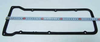
The valve cover covers and seals the timing belt, preventing grease from camshaft, valves and other parts from leaking out. In addition, new engine oil is poured through its neck when replacing. Therefore, a sealing gasket is installed between the valve cover and the cylinder head, which is changed every time after repair or adjustment of the valves.
Before replacing it, you should thoroughly wipe the surfaces of the cylinder head and cover to remove any remaining engine oil. Then the gasket is put on the cylinder head studs and pressed with the lid. It is necessary that the gasket fits exactly into the grooves of the cover. After this, the fastening nuts are tightened in a strictly defined sequence.