The serviceability of the steering system of any car is an important safety requirement on the road. Repair of the steering rack on Kalina must be carried out when any suspicious sounds occur. As practice shows, many car enthusiasts are calm about the fact that when turning the steering wheel there is a knocking or creaking noise, but this may indicate that the steering rack is knocking. Repairing the steering rack on Kalina is best done at a service station, but you can do it yourself.
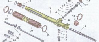
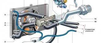
Steering mechanism: 1 – boot; 2, 20 – bolts; 3 – washer; 4 – oil seal; 5 – crankcase cover; 6, 17 – sealing rings; 7 – separator; 8 – drive gear with bearing; 9 – steering rack; 10 – left protective cap; 11 – rod support; 12 – bracket; 13 – plug; 14 – stop nut; 15 – stop spring; 16 – retaining ring; 18 – rack stop; 19 – stop liner; 21 – locking plate; 22 – cover plate; 23 – clamp; 24 – protective cover; 25 – right protective cap; 26 – steering gear housing
Design Features
The steering system of the Lada Kalina includes an electric power steering and a steering column that is adjustable in height and tilt. The steering mechanism is a steering rack with a variable transmission ratio. The rack engages with the engine crankcase through a gear having helical teeth, the pitch of which varies along the length of the rack. The figure shows the design of the Kalina steering rack.
The steering rack on Kalina is pressed against the gear by a spring. Friction is reduced by a plastic insert. The spring pressure is changed with an adjusting nut (the factory-set gap between the rack and the shaft is 0.1 mm). The second end of the rail rests against a plastic sleeve. Adjusting the gap helps eliminate knocking noises.
The steering system shaft is installed in bearings (one in the column bracket, the other in the electric booster housing). The column bracket is attached to the pedal bracket (front) and to the body bracket. The column bracket with the pipe is connected in the form of a hinge of two plates, which allows you to change the position of the steering wheel, and the range of movement is limited by the slots in the plates.
To fix the position of the pipe, there is a lever connected to the adjusting sleeve. It is screwed into a coupling bolt located in the slots of the plates. When you turn the lever, the bushing rotates, loosening the fixation of the plate, which allows you to change the position of the steering wheel. Springs between the plates and the bracket pull the pipe up when the fastening is loosened.
The steering system of the Lada Kalina has two tie rods and swing arms. The rod consists of external and internal tips and an adjusting threaded sleeve, which, when rotated, changes the length of the rod. The required adjustment of the rods is fixed with bolts. The rod is connected to the swing arm using an external tip that has a ball-type joint.
Kalina's electric power steering reduces the force applied to the steering wheel. It is assembled on the basis of an electric motor with a gearbox located under the steering system casing. The amplifier is controlled by an electronic unit that receives signals from sensors of vehicle speed, shaft rotation and steering torque.
The principle of operation of the amplifier is based on the fact that when the car is stationary, the torque on the steering shaft is the greatest, and when moving, it decreases with increasing speed. There is a power steering indicator on the dashboard.
Steering innovations
It seems like the issue has been resolved. Now it was possible to increase the force on the steering wheel, make the number of revolutions from lock to lock minimal, everything was smoothed out by the amplifier, but another problem arose. The car is operated in too different modes and the exact dosage of the steering angle at speeds of 140 and 55 km/h have completely different values. Not to mention the fact that there was almost no effort on the steering wheel, which made the steering even more insane. Then we had to change the design of the steering rack again. This time the objects of attention were the rack/pinion pair. Installing a new pair helped. The new steering rack was called “short” because the number of steering revolutions was reduced from 3.8 to 2.9. As a result, the waviness has almost disappeared and the steering wheel has become sharper.
This was achieved by using an uneven distribution of tooth pitch. In the central position of the steering wheel and at very small angles of rotation, the force on the steering wheel remains noticeable. This is very useful at high speeds. When actively maneuvering, in a parking lot, in heavy traffic and in cramped conditions, the greater the turning angle, the less force on the steering wheel. So the ten began to be controlled more clearly, without losing its lightness. How this affected the maintenance of the rack and its resource is a separate conversation.
Causes of extraneous sounds, removing the rack
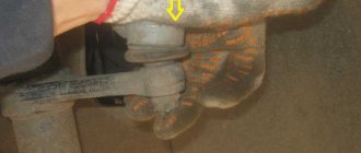
Situations often arise when, when turning the steering wheel of the Lada Kalina, you can hear something knocking and rattling. Such extraneous sounds can be heard constantly or appear after a long period of parking. If something rattles in the steering mechanism, then you should find out the causes of these noises. They often occur due to wear on the ball joint. Such a defect may result in the impossibility of traffic movement, and the part will need to be replaced in a timely manner.
The cause of knocking or squeaking of the steering wheel is sometimes damage to the grenade. If the steering racks are faulty, in addition to knocking, the steering wheel kicks back or signs of the steering wheel biting appear. In this case, the steering rack will need to be adjusted or repaired, and possibly replaced. Noises appear when the shock absorber bushings wear out. The knocking noise may be caused by loosening of the bolts securing the crankcase.
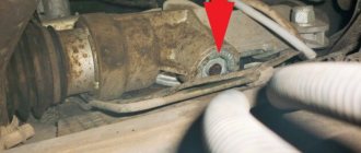
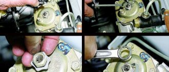
The design of the Kalina steering system is such that tightening the steering rack and adjusting the spring can only be done after removing the rack. It is removed in the following order. The front part of the car is raised using a lift or trestles. From the interior side, the bolt for the splined fastening of the steering column is turned out.
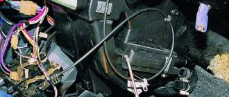
The mounting location is located below the pedal block. The front wheels of the car are removed. Then the nuts of the rotary cams are unscrewed and removed. The battery is removed from under the hood along with the platform. The heat reflector is removed. Finally, the nuts securing the steering rack to the body are unscrewed. After this, the rail can be removed out.
When disassembling, adjusting and repairing the Kalina steering rack, you will need the following tool:
- special key for adjusting the VAZ rack;
- dial-type gap indicator;
- screwdriver, pliers, set of socket wrenches and wrenches;
- hammer;
- mallet;
- steering wheel end remover;
- calipers;
- chisel;
- brush.
Any extraneous sounds when turning the steering wheel should make the driver wary. It is necessary to immediately find out the reasons for their appearance. Repairing and adjusting the Kalina steering rack can improve driving safety.
Video
This video shows how to repair the steering mechanism on Kalina.
Knock in Kalina steering rack. How to remove.
Installation of Kalina steering rack.
Repair of the steering column gearbox and the RR itself on Priora, Kalina, Grant.
How to install a steering rack from Kalina 2 to Kalina 1.
Steering rack for Lada Kalina Sport with a gear ratio of 3.1 instead of 4.02.
Do-it-yourself repair of the steering rack, but not Kalina, but Daevoo Sens / Daewoo Sens.
0
Author of the publication
offline 1 week
Adjusting the spring and power steering
Very often, the cause of a knocking sound when turning the steering wheel is a weakening of the pressure spring. It provides the required force for pressing the steering rack gear against the main shaft gear, which is set at the factory by adjusting and fixing the spring. As the vehicle is used, the spring loses its elasticity and relaxes.
In order to increase the pressing force of the spring, it is necessary to tighten it, which is done after disconnecting the steering mechanism, but without removing the steering rack. Repairing the steering rack in this case consists of setting the required gap between the rack and the shaft gear. The steering rack is installed in the middle position and is secured against movement.
The rubber plug is removed, and the indicator probe is placed in the hole of the stop adjusting nut so that it comes into contact with the rack stop. It is better to use a dial indicator. Then, turning the gear shaft that pushes the stop, the indicator measures the size of the stop's movement. The length of movement should not exceed 0.05 mm.
If this value is exceeded, it is eliminated by turning the adjusting nut. The steering rack is fixed in the position corresponding to the required clearance, and the ease of rotation of the pinion shaft is checked within the entire possible movement of the rack.
The adjustment nut is rotated using a special wrench for adjusting VAZ steering racks. It is not recommended to tighten the nut too much, which can have a negative effect when turning the steering wheel at maximum speed. If there is play when turning the steering wheel, the spring can be tightened by practically selecting the correct force.
In this case, initially the adjusting nut is turned by 20-25°, and the presence of knocking is checked when the rack is turned. If the noise is not eliminated, then tighten the nut again by 10-15°, and so on until the knocking noise is eliminated. If tightening the spring does not help, the steering rack needs to be repaired.
Adjusting Kalina's electric power steering is best done after removing the steering rack, but it can be done without dismantling with some inconvenience. The car is placed on the repair pit so that from below there is access to the mounting of the front part of the amplifier.
Assembly procedure
We begin repairing the VAZ-2110 steering rack by installing the needle bearing of the drive gear. The seat is first generously lubricated with a special lubricant such as “Fiol-1”. After this, we press a new ball bearing onto the drive gear shaft. Next, install the support sleeve from the repair kit inside the control unit housing. Now we fill the inner cavity of the column with lubricant and insert the steering rack into it.
We mount the drive gear and secure it with a locking ring and nut. We put a new boot on its shaft.
We install the stop with the seal in place, secure it with a stopper and a thrust nut. That's basically it. Now you need to adjust the control unit and put the protective cover on it.
Disassembling the steering rack and repairing it when jammed
If steering rack repair is required, it begins with disassembling it. During repairs, a steering rack repair kit is used. Disassembly is carried out in a certain order. First, the adjusting nut is unscrewed, which sometimes requires considerable effort. Then the thrust bushing is removed.
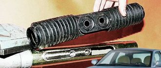
If it is difficult to remove, you can use a mallet to lightly hit the rack body. The side plugs and boot are removed after cutting off the plastic fasteners. For preventative purposes, it is recommended to replace the boot with a new one in any case. The shaft is removed from the rack housing by hitting the body with a mallet.
Steering rack parts: 1 – rack bushing ring; 2 – rack support sleeve; 3 – steering gear housing; 4 – roller bearing; 5 – drive gear; 6 – ball bearing; 7 – retaining ring; 8 – protective washer; 9 – sealing ring; 10 – bearing nut; 11 – lock washer; 12 – boot; 13 – rack; 14 – protective cap; 15 – rack stop; 16 – sealing ring; 17 – retaining ring; 18 – stop nut; 19 – clamp; 20 – protective cover; 21 – inner tie rod end; 22 – connecting plate; 23 – locking plate; 24 – bolt securing the rod to the rack; A - mark on the boot; B - mark on the crankcase
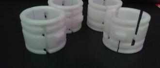
Inside the freed cavity of the housing, a plastic sleeve will become noticeable, which can be removed using a screwdriver. It must be replaced with a new one from the repair kit. All old grease is removed from the cavity of the steering rack housing; the surface is thoroughly cleaned, washed and blown.
New lubricant is applied both inside and outside the housing. Lithol is used for this purpose. Particular attention should be paid to lubricating the gearing areas. All rack parts are inspected and, if necessary, replaced with new ones from the repair kit. If the steering wheel is jammed, it must be removed. This operation for Lada Kalina is carried out as follows.
First, the airbags are disconnected from the battery, their locks and clamps are loosened. The cushions are released and moved to the side. The two horn wires are disconnected. On the steering wheel mounting shaft, in the place marked with an arrow, a mark is made on the location of the steering wheel before it is removed.
The steering wheel nut is loosened (but not completely unscrewed). When the steering wheel swings from side to side, it is tightened until it stops against the nut. Then you should align the car's wheels and ensure that the steering wheel is straight. The pin is removed and inserted into the switch block below the steering wheel.
The steering wheel must be locked at this time. Next, the wires are removed and the steering wheel is pulled out. All elements are checked and lubricated. The steering wheel is assembled in the reverse order.
Every Lada Kalina car owner will sooner or later be faced with the problem of steering rack failure and repair. Of course, experts and auto mechanics recommend changing this element, but not everyone can buy this element, so repair is the way out.
Video about steering rack repair on Lada Kalina:
The video material will tell you how to repair the steering rack, give basic recommendations and assembly features.
Choosing a high-quality steering wheel for the VAZ 2110
Of course, every car comes with its own steering wheel from the factory. Cars of the VAZ 2110 series are no exception.
However, the appearance, level of comfort and tactile sensations sometimes leave much to be desired. The rim often wears out quickly, the surface becomes smooth, which interferes with normal control.
Factory solution
Signs of a faulty steering rack
Steering rack repair kit
Before you begin repairing an element, you need to accurately determine that it is the steering rack on your car that has failed. For this, there are indirect and direct signs that will indicate the part. Of course, it is best to carry out diagnostics at a specialized car service center, but you can try with your own hands, for example, tighten the steering rack, but here you need to act carefully.
So, let's look at the main signs of a faulty steering rack:
- When turning the steering wheel there is a knocking noise under the hood.
- Longitudinal play of the steering wheel.
- Increased effort when turning the steering wheel.
- Oil stains under the car.
- Steering wheel sticks when turning.
All these signs are direct if the steering rack is faulty, which will be the first signs that the element needs to be diagnosed and repaired.
Causes of malfunction
General view of the steering
There are not many reasons for steering rack failure, but you need to know them. Timely maintenance, as well as diagnostics of the unit, can extend the life of the element.
Let's consider the main causes of steering rack malfunctions:
- Wear of elements that make up the rack.
- Damage due to an accident when the impact hit the wheel.
- Other reasons that caused the rack to start leaking.
All these reasons become the reason for repairing the steering unit.
Design characteristics
In order to repair the steering rack, you need to know its design and the elements that make up it. Let's look at the design diagram of the unit:
Steering rack diagram
Steering rack parts: 1 – rack bushing ring; 2 – rack support sleeve; 3 – steering gear housing; 4 – roller bearing; 5 – drive gear; 6 – ball bearing; 7 – retaining ring; 8 – protective washer; 9 – sealing ring; 10 – bearing nut; 11 – lock washer; 12 – boot; 13 – rack; 14 – protective cap; 15 – rack stop; 16 – sealing ring; 17 – retaining ring; 18 – stop nut; 19 – clamp; 20 – protective cover; 21 – inner tie rod end; 22 – connecting plate; 23 – locking plate; 24 – bolt securing the rod to the rack; A - mark on the boot; B - mark on the crankcase
What will be needed for repairs?
For restoration work related to the steering rack, a repair kit will be required. Usually, they cannot be found in specialized stores, and car enthusiasts, as a rule, go to the car market, where they can purchase a set of spare parts. In terms of price, this is much cheaper than buying a new rail.
The steering rack repair kit can be purchased either individually or as an assembly.
Repair kit for steering rack manufactured by Ricardo
2110-3403090-11 is the catalog number of a complete steering gear repair kit for the Lada Kalina. You can buy bushings and plastic inserts separately, but it is not recommended, since the quality of the products may be different, and accordingly, the wear on the left and right sides may differ.
Preparatory activities
The first thing you need to do is buy a steering rack repair kit. Without it, starting work is completely useless. The set may have different configurations.
- Minimum (washers, fasteners, bushings, nuts, bearings).
- Medium (in addition to all of the above, shafts are added). The cost of such a kit is twice as much.
- Maximum (everything is included here, including the rack).
Please note that there are different slats - old and new. The former are intended mostly for the VAZ 2108, and the latter for the VAZ 2110. It is better, of course, to give preference to the second option, because in this case the bushing is much easier to change (there is no need to disassemble the entire rack).
Dismantling and disassembling the rack on Lada Kalina
When all the materials for repairing the steering rack have been collected and purchased, you can proceed directly to the repair operations.
Before you begin, you need to completely clean the steering rack. This can be done manually, but it is best to use a steam mechanism under pressure, which will efficiently remove dirt and dust from all elements without damaging the parts.
Now, let's proceed to sequential operations to repair the steering rack:
Selection of repair kit
Before starting repair and restoration work, you should decide on the choice of repair kit.
Minimum set. This set includes the necessary list of fastening and sealing elements: washers, bearings, nuts and fluoroplastic bushings.
The basic set has bearings and shafts in addition to the minimum set, but its cost can be twice as high as the first option.
Please note that the steering rack can be either old or new. The old racks are designed for the VAZ 2108, while the new ones are designed for the “tenth” model. The new version is also more convenient to repair. If there is a need to repair the steering rack, which involves replacing the bushing, then there is no need to disassemble the entire mechanism. Remove the corrugation, unscrew the central nut and disassemble the rack into two component parts. One part will contain the mechanism, and the other part will be the one where the bushing is located.
Lada Kalina - Steering - Steering column - removal and installation
Note: Depending on the purpose of the work, the steering column can be removed as an assembly with the steering wheel and steering column switches. The operation is shown with partial disassembly of the steering column.
Removal
1. We prepare the car for work and remove the terminal from the negative terminal of the battery (see “Preparing the car for maintenance and repair”).2. Turn the steering wheel to a position that corresponds to driving in a straight line. Remove the steering wheel (see “Steering wheel - removal and installation”).3. Remove the decorative linings of the steering column (see “Decorative linings of the steering column - removal and installation”).4. Using a Phillips screwdriver, unscrew the three screws and remove the lower trim of the instrument panel.
Note: The steering column can be removed complete with the intermediate shaft. However, it is more convenient to remove and install the steering column if you disconnect the intermediate shaft. The connection of the intermediate shaft universal joint flanges is possible only in one position, so you do not need to mark their relative positions.
9. Using a 13 mm spanner, unscrew the nut of the coupling bolt connecting the universal joints of the intermediate shaft. We remove the bolt.
10. Using a 13 mm socket wrench, loosen the two nuts 1 of the lower steering column mounting. Using the same wrench, unscrew the two nuts 2 of the upper mounting of the steering column.
11. Remove the steering column assembly.
12. Using a 13 mm spanner, unscrew the nut of the coupling bolt of the flange of the lower cardan joint of the intermediate shaft. We remove the bolt.
13. Use a slotted screwdriver to open the flange and remove the cardan joint from the steering shaft splines.14. Using a marker or other available method, we mark the relative position of the flange of the upper universal joint and the steering shaft. Using a 13 mm socket wrench, unscrew the nut of the coupling bolt, holding the bolt head with a spanner of the same size.
15. Through the bevel we knock the cardan joint off the steering shaft splines.
Installation
Install the steering column in the reverse order. Before installation, make sure that the front wheels are in a straight line position, and the groove on the shaft and the mark on the steering gear housing cover, as well as the marks on the protective cover are located properly (see photo).
Location of marks for installing the steering gear shaft in the position of straight-line movement of the car: 1 - angular recess in the steering gear housing cover; 2 — groove on the steering shaft; 3 — steering gear housing cover; A - angular protrusion on the protective cover; B - cutout in the edge of the protective cover The protective cover must be put on the steering gear shaft so that mark A is located opposite the angular-shaped recess 1 located in the crankcase cover, and the shaft is rotated so that its groove 2 is located opposite mark B of the protective cover. Tighten the coupling bolt nuts on the flanges of the intermediate shaft to a torque of 23-28 Nm (2.3-2.8 kgf-m). Tighten the steering column mounting nuts to a torque of 15-18.6 Nm (1.5-1.9 kgf-m).
Characteristics of the steering mechanism of different modifications of Kalina
The steering mechanism (RM) is one of the most important elements of a car and is designed to change the trajectory of its movement. Control is carried out by turning the steering wheel, and the greater the angle of rotation, the more the car turns. Among the variety of PMs, rack and pinion mechanisms are most widespread due to their simplicity of design, low weight and size, high reliability and low cost.
All models and modifications of the Lada Kalina car have a standard safety rack and pinion mechanism, which is equipped with an electric amplifier.
The steering column can change its angle depending on the driver's height, ensuring comfortable driving. Currently, there are three manufacturers supplying components for electric power steering: Makhachkala, Aviaelectronics in Kaluga and Korea. All electric boosters are available for free sale and you can choose any one, but experienced drivers prefer the Korean device.
Removing the Kalina electric power steering column
- Medium Phillips screwdriver
- Large flat screwdriver
- Marker
- Open-end wrench 10 mm
- Open-end wrench 13 mm
- Driver for socket attachment
- High nozzle on the wrench 13 mm
- Knob attachment 13 mm
- Knob attachment 24 mm
1. Set the wheels to the straight-line position of the car.
2. Disconnect the wire terminal from the negative terminal of the battery.
3. Remove the steering wheel as described here. We remove the steering column switches as described here. Disconnect the ignition switch wire connectors from the instrument panel wiring harness connectors. If necessary, remove the ignition switch from the steering column.
4. Using a Phillips screwdriver, unscrew the three screws.
5. Then remove the lower cross member of the instrument panel.
6. Pressing the latches, disconnect the two wiring harness blocks from the power steering control unit. Disconnect the wiring harness connector from the steering column switch connector as described here.
7. Using a high “13” head, unscrew the four nuts securing the bracket (the fourth nut is not visible in the photo).
8. Lower the steering column to the floor.
9. If necessary, remove the connector for the steering column switches, as described here. Using a 13mm socket, unscrew the nut of the bolt securing the lower cardan joint to the steering gear shaft. If the bolt turns, hold it with a 13mm wrench.
10. Remove the bolt.
11. Using a powerful slotted screwdriver, release the terminal connection of the hinge.
12. Remove the intermediate propeller shaft from the steering gear shaft.
13. Before disconnecting the intermediate propeller shaft from the steering shaft, use a marker to mark the relative position of the upper joint of the propeller shaft relative to the steering shaft. Using a 13mm wrench, unscrew the nut of the hinge coupling bolt. If the bolt turns, hold it with a 13mm wrench. We take out the bolt.
14. Using a screwdriver, open the terminal connection of the hinge.
15. Remove the intermediate driveshaft from the steering shaft.
Intermediate cardan shaft
16. Install the intermediate driveshaft in the reverse order. When connecting the upper joint of the intermediate propeller shaft to the steering shaft, it is necessary to align the previously made marks. Install the steering column in the reverse order. Installation this way is best done with an assistant.
However, it is more convenient to install the column when the lower hinge of the intermediate propeller shaft is installed on the steering gear shaft in advance. To do this, after connecting the intermediate propeller shaft to the steering shaft, use a 13mm wrench to unscrew the nut of the intermediate shaft coupling bolt.
We carry out repairs
Remember that this unit is a rather “delicate” and fragile mechanism.
under the octagonal nut of the stop there is a spring that needs to be removed;
then remove the retaining ring, which is located under the specified spring;
lightly tap the wooden spacer to tap the rack stop out of the crankcase (note that there is a rubber sealing ring in the groove of the stop);
Next you need to remove the front shield seal;
- under the seal there is a boot, which is also removed (you can use a screwdriver that has a wide and thin blade);
- behind the boot there is a locking ring, which is also removed;
Using a 24mm octagonal head, unscrew the gear bearing mounting nut and remove the nut from the shaft;
we press out the shaft from the gear together with the bearing using a 14mm wrench, which we rest on the mounting blade; the shaft can be clamped in cleats;
How to remove and install a steering column
You will need: socket heads 13, 24, screwdrivers with Phillips and flat blades, a marker.
The steering column is one of the most important elements in ensuring traffic safety, so it is imperative to replace the shafts installed in the steering column for steering or the entire column in the event of such defects;
— deformation or damage to the intermediate shaft, play in the cardan joints, damage to the terminal connection of the lower joint with the steering gear shaft and the terminal connection of the upper joint to the steering column shaft;
— deformation or damage to parts and the steering column shaft, damage to the pins connecting the shaft to the steering wheel hub;
— damage to the mechanism for adjusting the position of the steering column;
— failure of the electric power steering control.
The steering column must be removed in this order.
1. Disconnect the wire in the battery from the negative terminal.
2. Remove the module from the airbag.
3. Remove the steering wheel.
4. Remove the steering column cover
5. Remove the steering column switches
6. Remove the airbag contact ring
7. Squeeze the clamp for the wiring harness block, disconnect the block from the contact group of the ignition lock (switch)
8. Release the clamp for the wiring harness block, disconnect the block from the antenna block from the immobilizer
9. Squeeze the clamp for the wiring harness block and disconnect the block from the electric power steering control unit
10. Similarly, disconnect the 2nd block from the block.
11. Mark, for example, with a marker how the lower cardan joint of the intermediate shaft and the steering mechanism shaft are mutually located.
12. Unscrew the nut from the coupling bolt of the steering column terminal connection.
13. Remove the bolt from the hole and disconnect the hinge from the steering mechanism shaft.
14. Unscrew the 4 nuts for securing the steering column to the dashboard frame and lower it down to the length of the wiring harness that you connect.
This is where the nuts for securing the steering column are located.
15. Squeeze the clamp for the wiring harness block, disconnect the column from the power steering.
16. Disconnect the holder for the wiring harness from the steering column bracket.
17. Disconnect the holder for the wiring harness from the bracket on the power steering.
18. Remove the steering column with the ignition lock (switch) and the intermediate shaft.
19. Install the steering column in the reverse order.
Electric power steering Lada Kalina | Auto repair
Removal and installation of electric power steering (EPS) Lada Kalina
On Kalina, the electromechanical power steering (EPS) is removed as an assembly with the steering column, for replacement, repair, or during the process of dismantling the instrument panel (dashboard).
To replace the EUR, you will need the following tool:
- two screwdrivers, Phillips and flathead
- socket wrench
- key
- spanner wrench
- knob
- head
- First of all, remove the negative terminal of the battery
- Using a curved screwdriver, unscrew the screws securing the lower and upper steering shaft housings
- lower the steering shaft adjustment lever and remove the covers
4. remove the steering column switches, having previously disconnected the harness pads
5. remove the horn switch cover by pulling it towards you
6. disconnect the wires from the horn switch
7. Using a wrench and a socket, unscrew the steering wheel fastening nut (we do not unscrew the nut completely)
8. Rocking the steering wheel from side to side, pull it towards you and remove it from the splines
9. Unscrew the nut completely and remove the steering wheel (before removing the steering wheel, use a marker to mark its position relative to the splined part of the shaft)
10. Unscrew the three screws securing the transverse reinforcement of the instrument panel and remove it
11. Using a socket wrench, unscrew the 4 nuts securing the bracket and lower the steering column
12. disconnect the wiring harness blocks from the ignition switch and the power steering controller
13. lower the steering column to the floor
14. Mark with a marker the position of the propeller shaft relative to the steering column shaft
15. Use a wrench to unscrew the bolt securing the intermediate cardan joint to the lower cardan joint, remove the bolt, and remove the steering column assembly with the electric power steering.
Reassemble in reverse order
Reasons for replacement
There are more than enough reasons to want to replace your steering wheel. But everyone has their own:
- The old steering wheel was worn out;
- The current rim does not meet the driver's requirements;
- The driver feels uncomfortable with the factory steering wheel;
- The unit received mechanical damage;
- Tuning, modifications to the interior and the entire car, etc. are carried out.
Drivers can name many more reasons why they want to get a new one to replace their old steering wheel.
Option for tuning
LADA KALINA: Removing the steering column with electric power steering
We set the wheels to the position of straight-line movement of the car. Disconnect the wire terminal from the “negative” terminal of the battery. Remove the steering wheel. Remove the steering column switches. Disconnect the ignition switch wire blocks from the instrument panel wiring harness blocks. If necessary, remove the ignition switch from the steering column
Using a Phillips screwdriver, unscrew the three screws.
. and remove the lower cross member of the instrument panel.
By pressing the clamps, disconnect the two wiring harness blocks from the power steering control unit. Disconnect the wiring harness block from the steering column switch connector.
Using a high “13” head, unscrew the four nuts securing the bracket (the fourth nut is not visible in the photo).
. and lower the column to the floor. If necessary, remove the connector for the steering column switches.
Using a 13mm socket, unscrew the nut of the bolt securing the lower cardan joint to the steering gear shaft. If the bolt turns, hold it with a 13mm wrench.
Using a powerful slotted screwdriver, release the terminal connection of the hinge.
. and remove the intermediate propeller shaft from the steering gear shaft. Before disconnecting the intermediate propeller shaft from the steering shaft, use a marker to mark the relative position of the upper joint of the propeller shaft relative to the steering shaft.
Using a 13mm wrench, unscrew the nut of the hinge coupling bolt. If the bolt turns, hold it with a 13mm wrench. We take out the bolt
Use a screwdriver to loosen the terminal connection of the hinge.
. and remove the intermediate driveshaft from the steering shaft.
Intermediate driveshaft Install the intermediate driveshaft in the reverse order. When connecting the upper hinge of the intermediate propeller shaft to the steering shaft, it is necessary to align the previously made marks. Install the steering column in the reverse order. Installation in this way is best done with an assistant. However, it is more convenient to install the column when the lower hinge of the intermediate propeller shaft is installed on the steering gear shaft in advance. To do this, after connecting the intermediate propeller shaft to the steering shaft..
. Using a 13mm wrench, unscrew the nut of the intermediate shaft coupling bolt. . remove the bolt.
. and disconnect the lower universal joint from the upper one. We install the lower hinge on the steering gear shaft (the bolt securing the hinge to the gear shaft should be located vertically on the right side). We turn the steering shaft so that the hole in the upper hinge for the intermediate shaft pinch bolt is located horizontally at the bottom of the shaft. We connect the upper and lower hinges of the intermediate shaft, insert the coupling bolt and tighten the nut. We carry out further installation in the reverse order.