Nuances of work
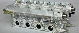
At different times, Lada Priora cars were equipped with engines with a displacement of 1.6 and 1.8 liters and a different number of valves in the heads - V8 (or 8V) and V16 (or 16V). The type of unit head determines the size of the bolts, the order of their installation and the tightening torque of the cylinder head on the Priora.
If the car has an 8-valve engine, then it can use head mounting bolts of different sizes:
- on old motors 21114, M12*1.25 hex head screws are used;
- on more modern 21116, which went into production approximately in mid-2011, M10*1.25 elements with an asterisk head are installed.
When installing a removed head, it is necessary to use new screws, since the old ones will be stretched and have internal damage.
Also, the engines use gaskets of different designs - combined on the old unit and all-iron on the new one. The procedure for tightening bolts for engines with metal and combined gaskets is absolutely identical.
The main nuances when performing work are checking the length of the fasteners, observing the sequence of tightening the screws and monitoring the tightening force. Violation of these conditions leads to damage to parts and the need for additional repair work. The procedure itself is not complicated and can be done independently in any convenient place - in a garage or in an open parking lot, with the exception of the case of installing the head on the engine, which is preferably installed indoors.
It is important to remember that tightening the bolts “by eye” without a torque wrench is unacceptable, since a uniform fit of the mating surfaces of the head and block will not be ensured.
Tools and materials
Before starting the tightening procedure, you should prepare everything necessary to perform:
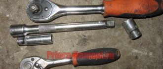
- wrench with built-in dynamometer up to 100 H⋅m;
- a set of sockets and regular keys;
- Togh E14 key;
- calipers for measuring the remaining length of bolts;
- plate with a marked scale up to 180 degrees;
- new bolts.
A torque wrench is an important tool for DIY repairs.
Step-by-step instruction
Sequence of operation on an 8 valve engine:
- Wipe the cylinder head surfaces and dry the bolt holes in the engine block.
- Install the gasket on the block and align it along the guides.
- Mount the head on top and insert 10 M10 or M12 mounting bolts. If the owner decides to save money and keep the old screws, then they should have a length of no more than 135.5 mm.
- Tighten the elements according to the diagram. The tightening force should not exceed 20 N⋅m.
- Then you need to re-tighten the bolts. The second tightening force should be in the range from 70 to 85 N⋅m.
- Next, you need to tighten the screws by 90 degrees in the same sequence. The rotation angle can be controlled using a special device, which is a plate with an attached scale from 0 to 180 degrees.
- In accordance with the regulations, you need to tighten the bolts again by 90 degrees.
- The attachment of the 8 valve head to the block is complete.
- After assembling the motor, you need to check the quality of operation by starting and warming up the engine. A securely tightened joint between the head and the block should not allow working fluids to leak from the crankcase of the power unit.
Homemade device for controlling the rotation angle
If a more powerful and modern engine with sixteen valves is installed on a car, for example, the VAZ 21126 model or 126 for short, the procedure for pulling the bolts has its own characteristics.
In order to correctly tighten the cylinder head screws on such units, you need to:
- Remove oil from the mating surfaces and check that there is no liquid in the bolt holes.
- Install the gasket, center it and place the head on top.
- Insert 10 mounting screws M10*1.25 into the guide holes, having previously lubricated the threads with engine oil. If you decide to use old bolts, which is permissible for 16 valve heads, then their remaining length should not exceed 98 mm.
- Perform preliminary pulling according to the scheme with a torque of 12-20 N⋅m.
- Increase the tightening degree to 26-34 N⋅m and re-run all the bolts in the same sequence.
- Then you need to tighten the screws 90 degrees, with a force of about 50 N⋅m.
- Repeat tightening by 90 degrees again, the torque on the key will be approximately 80 N⋅m. Some instructions recommend waiting up to 20 minutes between turns, but in practice no advantages of such a scheme have been identified.
- After assembling the power unit, you should check the quality of the work performed.
The procedure for pulling the head on 1.8 liter engines, which are 1.6 liter engines with an enlarged cylinder, is completely identical to that described above.
If during the work process the correct moment of force is applied to the bolts, corresponding to design calculations, then the gasket will be evenly and tightly pressed along the joint, ensuring a reliable and tight connection. It is important to note that if it is necessary to remove the cylinder head from the engine, then the screws are also loosened according to the scheme established by the regulations. Chaotic unscrewing of the elements will lead to deformation of the head and the appearance of invisible microcracks.
Cylinder head repair
We mark all hydraulic compensators with numbers using an ordinary clerical touch and put them away. An ordinary magnet will help you pull them out. We dry out the valves and remove the oil seals (valve seals), the valves into scrap metal, the oil seals into the trash. We clean all channels. We take the head for grinding, just in case. After washing it again with kerosene after sanding and blowing it with air, we begin to assemble it.
We arrange the freshly purchased valves in the sequence in which they will stand in the cylinder head and begin to grind in one by one. Lubricate the valve stem with clean oil and apply lapping paste to the edge.
We insert the valve into place and put a valve grinding tool on the valve stem. The stores sell a device for manual lapping, but since this is the twenty-first century, we are mechanizing the process. We take the old valve and cut off the rod from it, select a rubber tube for it of such a diameter that it fits tightly. The rod is in a reversible drill, one end of the tube is on it, the other is on the valve being ground in. At low speeds we begin to grind the valve, constantly change the direction of rotation and periodically press it to the seat or weaken the force. On average, the valve takes about twenty seconds. We take it out and wipe it. The valve is considered ground in if a uniform gray strip of at least 1.5 mm wide appears on the chamfer.
The same stripe should appear on the valve seat.
Video of manually grinding valves
For a sixteen valve head, everything is the same, only there are twice as many valves.
After lapping, all valves and seats are thoroughly wiped and washed with kerosene to remove any remaining lapping paste. We check for leaks. We tighten the old spark plugs and put all the valves in place. Pour kerosene and wait three minutes, if the kerosene does not run away all is well, otherwise we grind the valves on this cylinder.
We had to grind four valves again, after which the kerosene stopped flowing.
We stuff new valve seals.
We put the valves in place and dry them. Before doing this, lubricate the valve stems with clean oil. After lubricating it with clean oil, we put the hydraulic compensators in place and, covering them with a clean cloth, remove the head out of sight. We're done with the cylinder head.
Features of tightening fasteners
Even a non-professional can handle this work.
It is important to follow two rules - the tightening torque and the sequence of working with fasteners. The tightening torque on engines with 8 and 16 valves is no different, while the sequence is different. Pay attention to the diagrams below; numbers indicate the order of tightening the bolts. It is necessary to pay attention to the cylinder block:
- if during operation the bolts become loose due to vibration (the malfunction is detected by leakage of the gasket);
- after dismantling the cylinder head and installation;
- if the iron gasket is replaced;
- during tuning of the cylinder block.
Before work, take the instructions from your Priora to understand which engine is installed in the car.
Downloading a book
After successfully completing the payment (by any method) and returning to the KrutilVertel store from the payment system website, you will be taken to the successful payment page:
The book you purchased will be in your personal account, from where you can always download it.
Please note that after making the payment, you need to return back from the payment system website to the KrutilVertel website. If for some reason you did not return back to the site and closed the payment system tab with a message about the successful completion of the payment, please let us know - we will send you a letter indicating access to download the book
If for some reason you did not return back to the site and closed the payment system tab with a message about the successful completion of the payment, please let us know - we will send you a letter indicating access to download the book.
Removing and installing connecting rods on the Priora engine
The interesting thing is that, although this part is located almost in the middle of the engine, it can be removed without removing the engine from the car. Yes, this is, of course, not an easy operation, but it is quite doable. It must be carried out either in an inspection hole or on a special lift for cars so that there is access to the oil pan. When the vehicle is positioned for surgery, the engine compartment protection underneath is removed first. The cylinder head, engine sump and flywheel are dismantled. It is advisable to remove the oil intake so as not to damage it. You can start removing the connecting rods.
It is worth starting from the first cylinder. This is in order to put the details in order and not get confused. Rotate the Priora crankshaft so that the lower part of the connecting rod is level in the lower position. Unlock and unscrew the bolts securing the liner cover. Remove it and set it aside along with the liner itself. After this, push the piston up and remove it from the cylinder. One by one, remove all the Priora pistons and connecting rods in this manner. Now you can repair or replace elements.
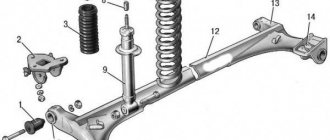
crank mechanism
This main engine unit consists mainly of the following groups:
Each part of the group has several additional elements. For example, each piston carries a set of O-rings, a connecting pin and pin retaining clips. The crankshaft has bearings and oil seals. The most interesting thing is the structure of the connecting rods.
The principle of operation of the mechanism
VAZ engines, like other cars, are based on explosive combustion of fuel. The piston creates a certain compression of the air-gasoline mixture, a spark from the spark generator ignites it, pushing the piston down, and the crank mechanism (CPM) converts translational motion into rotational motion. This occurs due to the special shape of the crankshaft. The mounting points of the connecting rods are located so that while the connecting rods pushing the pistons rise, the connecting rods pushed by the piston are lowered. And this process takes place in shifts.
Set of connecting rods "Priors"
These parts are collapsible. The main part is made of high quality metal. Only in the upper ring, where the piston locking pin fits, is an insert made of a different metal installed. In general, the connecting rod consists of the following parts:
- connecting rod;
- liner covers;
- coupling bolts 2 pcs.;
- special washers;
- connecting rod bearing.
This is due to the fact that the liners have special grooves for the passage of engine oil. Due to the high rotation speed, this unit requires uniform and abundant lubrication. The slightest discrepancy between these grooves and the oil supply holes of the crankshaft will lead to a disruption in the flow of lubricant and, as a result, jamming of the engine.
Is it worth observing the tightening torque of the main and connecting rod bearings when assembling the engine?
Many car enthusiasts who are accustomed to repairing their cars themselves know firsthand that engine repair is a very difficult and responsible task.
Since repairing a power unit requires from the car owner not only certain skills, but also knowledge to correctly carry out the technological process. Today in the article we will briefly look at the crank mechanism and its role in a car engine.
In addition, we will also talk about the importance of observing the tightening torque of the main and connecting rod bearings, the nuances and sequence of this operation, and other important aspects. Therefore, it will be useful for beginners to somewhat expand their knowledge of the topic by reading our article.
The concept of CVM
The crank mechanism, abbreviated as KShM, is the most important unit unit for the engine. The main task of this mechanism is to change the linear movements of the piston into rotational ones, and vice versa. This torque occurs due to the combustion of fuel in the engine cylinders.
As you know, gases tend to expand during combustion of a fuel mixture. Then, under great pressure, they push the engine pistons down, and they, in turn, transmit force to the connecting rods and crankshaft. It is due to the specific shape of the crankshaft that the engine transforms one movement into another, which ultimately allows the wheels of the car to rotate.
In terms of its functions, the crankshaft is the busiest engine mechanism. It is this unit that determines what type of power unit will have and how the cylinders will be located in it. This is due to the fact that each type of engine is created for a specific purpose. Some cars require maximum engine power, light weight and dimensions, while others prioritize ease of maintenance, reliability and durability. Therefore, manufacturers produce different types of crank mechanisms for different types of engines. KShM are divided into single-row and double-row.
The role of crankshaft liners
The crankshaft must withstand heavy loads while the engine is running. But bearings cannot be used for this device. This role was taken on by the main and connecting rod bearings. Although, according to their task, they perform the functions of sliding bearings. The liners are made from a bimetallic strip consisting of low-carbon steel, copper and lead, as well as an aluminum alloy ASM or Babbitt.
It is thanks to the liners that the free rotation of the crankshaft is ensured. To ensure durability and wear resistance, the liners are coated with a thin, micron layer of oil during engine operation. But for their complete and high-quality lubrication, high oil pressure is simply necessary. This role was taken over by the engine lubrication system. All these conditions contribute to reducing the friction force and increasing the service life of the engine.
Types and sizes of liners
In general, crankshaft liners are divided into two groups:
- The first type is called radical liners. They are located between the crankshaft and the places where it passes through the engine housing. They bear the greatest load, since it is on them that the crankshaft is attached and rotates.
- The second group includes connecting rod bearings. They are located between the connecting rods and the crankshaft and its journals. They also carry enormous loads.
Main and connecting rod bearings are manufactured individually for each engine type with their own dimensions. Moreover, for most automobile engines, in addition to the nominal factory sizes, there are also repair inserts. The outer size of the repair liners remains unchanged, and the inner diameter is adjusted by increasing the thickness of the liner. There are four such sizes in total, with increments of 0.25 mm.
It is no secret that with high mileage of a car, not only the main and connecting rod bearings wear out, but also the crankshaft journals. These circumstances lead to the need to replace liners of nominal sizes with repair ones. To install one or another repair liner, the neck is bored to a certain diameter. Moreover, the diameter is selected individually for each size of the liner.
If, for example, a repair size of 0.25 mm has already been applied, then when getting rid of imperfections on the crankshaft journals, a size of 0.5 mm should be used, and in case of serious scuffing, 0.75 mm. If the bearings are replaced correctly, the engine should last for more than one thousand kilometers, unless, of course, the other systems of the car are in good working order.
There are also options when boring is not required and the liners are simply replaced with new ones. But people who do this professionally do not advise simply replacing the earbuds with new ones. This is explained by the fact that during the operation and operation of the liners, microdefects still appear on the shaft that are not visible at first glance. In general, without grinding there is a possibility of rapid wear and a short service life of the crankshaft.
Signs of wear on the main and connecting rod bearings
In the conversations of car enthusiasts, phrases are often heard: “The engine knocked” or “The liners turned,” these words most often refer to the wear of the liners. This in turn is a serious breakdown in the motor. The first signs of such malfunctions are loss of oil pressure or the appearance of extraneous sounds when the engine is running. It will be difficult for an inexperienced car enthusiast to identify signs of faulty liners, so it is better to immediately contact a specialist.
For a professional, listening and making a diagnosis will not pose any serious problems. Typically, this procedure is performed at idle speed of the engine, sharply pressing the gas pedal. It is believed that if there is a dull tone or an iron grinding sound, then the problem is in the main bearings. If there is a problem with the connecting rod bearings, the knocking sound is louder and stronger.
There is another way to check wear. It is necessary to alternately unscrew the spark plugs or injectors of diesel engines. If the knocking noise disappears when you unscrew a spark plug, then this is the cylinder in which there are problems.
The problem of low oil pressure may not necessarily arise from wear of the liners. The oil pump, pressure relief valve may be faulty, or the camshaft bed may be worn out. Therefore, we first check all the components of the lubrication system and only after that we draw conclusions about what exactly to repair.
We measure the gap between the liner and the crankshaft
The inserts are produced in 2 separate parts, which have special places for installation. The main task during assembly is to ensure the required clearance between the shaft journal and the liner. Typically, a micrometer is used to determine the working gap between them, and a bore gauge measures the inner diameter of the liners. After this, some calculations are made, which make it possible to identify the gap.
However, it is much easier to perform such an operation using a special plastic calibrated wire. Pieces of the required size are placed between the liner and the journal, after which the bearing is clamped with the required force and disassembled again. Next, take a special ruler, which comes in the kit along with the wire, and measure the width of the corresponding imprint on the shaft. The wider the crushed measuring strip, the smaller the bearing clearance. This method allows you to control the required distance between the neck and the liner with high accuracy.
How and with what force are the main and connecting rod bearings tightened?
You can tighten the main and connecting rod bearings with the required force using a special torque wrench. The key can be either a ratchet or an arrow. Both wrenches are marked with the dimensions required to tighten the nuts and bolts to any torque. To configure, you will need to set the required value on the key, and after that you can immediately begin tightening.
Remember that for a force of less than 5 kg there is no need to put a pipe on the wrench to create additional leverage. This can be done with one hand to avoid stripping the bolt threads.
Tightening torque for main and connecting rod bearings
Before installing the liners, the first step is to remove the preservative grease from them and apply a small layer of oil. Next, we install the main bearings in the bed of the main journals, not forgetting that the middle liner is different from the others.
The next step is to place the bed covers and tighten them. Moreover, the tightening torque must be applied in accordance with the standards that are sometimes specified in the operating rules of the vehicle. But most often there are cases when the technical manual for the car does not indicate the tightening torque for the main and connecting rod bearings. In such cases, it is recommended to look for this information in special literature on repairing a specific engine. For example, for Lada Priora cars, the tightening torque for the bed covers ranges from 64 N*m (6.97 kgf*m) to 81 N*m (8.61 kgf*m).
Next, we proceed to install the connecting rod bearings. In this case, you should pay attention to the correct installation of the covers; each of them is marked, so do not mix them up. Their tightening torque is much less than that of the main ones. For example, if we take the same Lada Priora model, the tightening torque of the connecting rod bearings will start from approximately 43 N*m (4.42 kgf*m) to 53 N*m (5.46 kgf*m).
Please note that the data provided for example assumes the use of new liners for repair, and not used parts. Otherwise, when using the old liners, the tightening torque should be selected based on the upper limit of the recommended torque from the documentation for this engine. This is done due to the possible presence of some wear on old parts. Sometimes ignoring this fact can lead to significant deviations from the recommended norm.
When all the bolts are tightened for the first time, it is advisable to rotate the shaft. To do this, there is a place on the side of the crankshaft for a wrench, calmly turn it clockwise. If the ring has burst or there is any other malfunction, it will be immediately visible. Next, after making sure that there are no problems, we check all the bolts again with a wrench at the tightening torque.
It should be remembered that the tight fit of the sliding bearings to the crankshaft and, accordingly, the efficiency of the engine itself depend on how correctly this process is performed. Because if the bolt is not fully tightened, there will be excess oil, the entire lubrication cycle will be disrupted, and can also lead to breakage of the liner. If we overtighten, the liner will begin to overheat and there will no longer be enough lubricant. Ultimately, the liner may completely melt and rotate, which will lead to a major overhaul of the engine.
Replacing the cylinder head gasket on a VAZ 2170 2171 2172 Lada Priora
Operations performed when replacing the cylinder head gasket on a VAZ 2170 2171 2172 Lada Priora
If an external leak of engine oil or coolant is detected at the junction of the head and cylinder block, remove the head and replace its gasket. A leak can also occur due to warping of the block head due to overheating. In the absence of sealing on the cylinder head gasket into the internal cavities, antifreeze can get into the oil which begins to foam (foam can be seen especially clearly on the filler neck and in the cavity of the valve cover), in addition, an oil film may appear in the antifreeze. In case of this malfunction, it is necessary to replace the gasket as soon as possible, since this malfunction can lead to engine failure due to the incorrect operation of two systems at once - lubrication and cooling.
Tools required when replacing the cylinder head gasket on a VAZ 2170 2171 2172 Lada Priora
You will need: a torque wrench, “13”, “17”, “19” keys, “10”, “13”, “17” socket heads, “10” hex key, screwdriver.
Warning
The head gasket is a one-time use unit, so each time the head is removed, the head gasket must be replaced.
Interchangeability of cylinder head gaskets for Priora, Tenth Family, Lada Kalina.
Fig. 1 Cylinder head gaskets (engines: 21126,11194,21124)
In addition, I would like to touch upon the issue of interchangeability and features of the cylinder block gasket for engine 21126 and earlier versions 21124. The cylinder head gasket for engine 21124 (Fig. 1) is non-shrinkable, made of non-asbestos material with metal cylinder seal edgings produced by Fritex, Yaroslavl, or VATI, Volzhsky . The 21126 engine has a Federal Mogul gasket - metal, two-layer with spring ridges to seal the gas joints and the lubrication system channel. The cylinder head gasket from engine 21124 is not interchangeable with the gasket from engine 21126 Lada Priora. On engine 11194 there is a similar metal gasket, only with smaller diameters of the holes for the cylinders - 76.5 mm. Thanks to the new cylinder head gasket used on the Lada Priora, the deformation of the cylinder walls has been significantly reduced. Together with piston rings of a new design (less height and tangential force), a reduction in the mass of the connecting rod and piston set and an increase in the length of the connecting rod, this significantly reduced friction losses, oil consumption due to waste and the breakthrough of gases from the combustion chamber into the engine crankcase. Read more about replacing the cylinder head gasket on a VAZ 2170 2171 2172 Lada Priora
Sequence of operations when replacing the cylinder head gasket on a VAZ 2170 2171 2172 Lada Priora
1. Remove the decorative engine casing (see “Removing and installing the decorative engine casing on a VAZ 2170 2171 2172 Lada Priora”). 2. Set the piston of the 1st cylinder to the TDC position of the compression stroke (see “Installing the piston of the 1st cylinder to the TDC position of the compression stroke on a VAZ 2170 2171 2172 Lada Priora”). 3. Reduce the pressure in the power system if the work is performed immediately after a trip (see “Reducing the fuel pressure in the engine power system on a VAZ 2170 2171 2172 Lada Priora”). 4. Disconnect the wire from the negative terminal of the battery. 5. Drain the coolant (see “Replacing the coolant on a VAZ 2170 2171 2172 Lada Priora”). 6. Remove the air filter (see “Removing and installing the air filter on a VAZ 2170 2171 2172 Lada Priora”). 7. Disconnect from the throttle assembly the heating hoses, the small branch of the crankcase ventilation system, the canister purge, the air supply hose, the wiring harness blocks of the throttle position sensor and the idle speed regulator (see “Removing and installing the throttle assembly on a VAZ 2170 2171 2172 Lada Priora ( Lada Priora)"). 8. Remove the throttle assembly (see “Removing and installing the throttle assembly on a VAZ 2170 2171 2172 Lada Priora”). 9. Disconnect the wiring harness connectors from the ignition coils. Remove the ignition coils and unscrew the spark plugs (see “Replacing and servicing spark plugs on a VAZ 2170 2171 2172 Lada Priora”). 10. Disconnect the wiring harness block from the emergency oil pressure drop sensor...
11. ...from the coolant temperature sensor of the engine management system...
12. ...and phase sensor.
13. Loosen the clamps and disconnect the five cooling system hoses from the thermostat pipes.
14. Disconnect the wiring harness connector from the coolant temperature gauge sensor.
15. Using a 13mm wrench, unscrew the nut securing the tip of the “mass” wire...
16. ...and remove the wire.
17. Unscrew the nut of the fuel hose fitting and disconnect it from the fuel line tube.
Warning
The tip of the fuel line tube is sealed with a rubber ring. Don't lose it during disassembly. Replace a severely compressed or torn sealing ring.
18. Unscrew the screw of the pressure plate of the bracket securing the fuel line to the cylinder head and remove the plate.
Removing and installing connecting rods on the Priora engine
The interesting thing is that, although this part is located almost in the middle of the engine, it can be removed without removing the engine from the car. Yes, this is, of course, not an easy operation, but it is quite doable. It must be carried out either in an inspection hole or on a special lift for cars so that there is access to the oil pan. When the vehicle is positioned for surgery, the engine compartment protection underneath is removed first. The cylinder head, engine sump and flywheel are dismantled. It is advisable to remove the oil intake so as not to damage it. You can start removing the connecting rods.
It is worth starting from the first cylinder. This is in order to put the details in order and not get confused. Rotate the Priora crankshaft so that the lower part of the connecting rod is level in the lower position. Unlock and unscrew the bolts securing the liner cover. Remove it and set it aside along with the liner itself. After this, push the piston up and remove it from the cylinder. One by one, remove all the Priora pistons and connecting rods in this manner. Now you can repair or replace elements.
Torque and sequence of tightening the camshaft bed
Camshaft cover tightening sequence
Correct tightening of the camshaft bed, as well as other parts of the cylinder head, determines the normal functioning of all components and assemblies. So, in order to tighten threaded connections, a standard tightening pattern and a torque wrench are used.
Before installing the bolts in place, they must be washed thoroughly and lubricated with silicone grease.
In order to properly tighten the bolts, you need to know the sequence. It starts from the middle part and gradually moves directly to the edges. The detailed sequence can be seen in the photo below.
Tightening diagram for each camshaft bed bolt with numbering
As for the tightening force itself, it is 8.0-10.0 Nm. After the bed is installed on the block head, the connection bolts are tightened by hand or without much force using a ratchet with a head.
We tighten all the bolts by hand, but do not tighten them
When all the bolts are in place, you need to take a torque wrench and tighten them according to the standards in the order indicated above.
Torque wrench for tightening threaded connections
In what cases is it necessary to tighten the camshaft bed?
The bolts are tightened. Marked with arrows
Tightening the camshaft bed will be necessary if it was previously dismantled for restoration and repair work. So, in what cases will you need to remove the bed, let’s look at it in more detail:
- Replacing camshafts, lifters or valve seals.
- Overhaul of the block head.
- Engine repair operations.
- Replacement of individual elements of the cylinder head.
Consequences of improper bed tightening
The consequences of improperly tightening the camshaft bed include the following:
- Oil leakage due to a gap or loose connection.
- Passing air inside the cylinder head.
- Malfunction of the engine or cylinder head.
- Ingress of foreign objects (water, dirt, dust).
Let's start to disassemble
Tightening torque of the cylinder head of a ZMZ 406 gazelle engine with a torque wrench
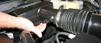
First, drain the oil and antifreeze. We remove the protective cover, the air filter with pipes, disconnect the ignition coil connectors, the throttle cable and the throttle assembly.
We remove the thermostat housing and simultaneously disconnect all the available connectors and pipes. We remove all the wiring that was in our way towards the battery.
We remove the generator. We unscrew the eight thirteen nuts holding the intake manifold and remove it. We unscrew all the bolts securing the valve cover, as well as the side engine support.
Remove the timing belt, camshaft pulleys and pump.
In three passes, so as not to deform the part, we first loosen and then unscrew twenty bolts of the camshaft bearing housing, the head is eight. Be sure to follow the sequence shown in the photo.
Remove the bearing housing. We remove the camshafts; there is a distinctive lip on the intake camshaft.
Also, in several passes, we first loosen and then unscrew the ten cylinder head mounting bolts. Be sure to follow the sequence shown in the photo.
Tighten the engine bolts correctly
All my life I have been surrounded by cars! First, in the village, already in the first grade, I was rushing around on a tractor through the fields, then there was JAVA, then a penny. Now I am a third-year student at the Polytechnic Faculty of Automotive Engineering. I work part-time as a car mechanic and help repair cars for all my friends.
In the table below we have indicated the tightening torques for all threaded connections on the VAZ-2112 engine.
Tightening torque of threaded connections (table)
| Detail | Thread | Tightening torque, N m (kgf m) |
| Engine | ||
| Cylinder head bolt | M12x1.25 | The cylinder head mounting bolts must be tightened in four steps: 1 – to a torque of 20 Nm (2 kgf); 2 – torque 69.4–85.7 (7.1–8.7 kgf); 3 – turn 90°; 4 – turn it 90° again. |
| Nut of the stud securing the intake pipe and exhaust manifold | M8 | 20,87–25,77 (2,13–2,63) |
| Tension roller nut | M10×1.25 | 33,23–41,16 (3,4–4,2) |
| Camshaft bearing housing stud nut | M8 | 18,38–22,64 (1,87–2,31) |
| Camshaft pulley bolt | M10 | 67,42–83,3 (6,88–8,5) |
| Accessory housing mounting bolt | M6 | 6,66–8,23 (0,68–0,84) |
| Nut of the stud securing the exhaust pipe of the cooling jacket | M8 | 15,97–22,64 (1,63–2,31) |
| Main bearing cap bolt | M10x1.25 | 68,31–84,38 (6,97–8,61) |
| Oil sump bolt | M6 | 5,15–8,23 (0,52–0,84) |
| Connecting rod cap bolt nut | M9x1 | 43,32–53,51 (4,42–5,46) |
| Flywheel bolt | M10x1.25 | 60,96–87,42 (6,22–8,92) |
| Coolant pump mounting bolt | M6 | 7,64–8,01 (0,78–0,82) |
| Crankshaft pulley bolt | M12x1.25 | 97,9–108,78 (9,9–11,1) |
| Coolant pump inlet pipe mounting bolt | M6 | 4,17–5,15 (0,425–0,525) |
| Muffler exhaust pipe fastening nut | M8×1.25 | 20,87–25,77 (2,13–2,63) |
| Nut securing the flange of the additional muffler | M8×1.25 | 15,97–22,64 (1,63–2,31) |
| Nut securing the clutch cable to the engine bracket | M12x1 | 14,7–19,6 (1,5–2,0) |
| Front engine mount bracket bolt | M10x1.25 | 32,2–51,9 (3,3–5,5) |
| Front engine mount bolt nut | M10 | 41,65–51,45 (4,25–5,25) |
| Nut of the bolt securing the left suspension support of the power unit | M10 | 41,65–51,45 (4,25–5,25) |
| Nut securing the bracket of the left suspension support of the power unit | M10 | 31,85–51,45 (3,25–5,25) |
| Bolt securing the rear suspension support of the power unit | M10x1.25 | 27,44–34 (2,8–3,47) |
| Nut of the power unit rear suspension bracket mounting bolt | M12 | 60,7–98 (6,2–10) |
| Bolt securing the oil receiver to the main bearing cover | M6 | 8,33–10,29 (0,85–1,05) |
| Bolt securing the oil receiver to the pump | M6 | 6,86–8,23 (0,7–0,84) |
| Oil pump mounting bolt | M6 | 8,33–10,29 (0,85–1,05) |
| Oil pump housing bolt | M6 | 7,2–9,2 (0,735–0,94) |
| Oil pump pressure reducing valve plug | M16x1.5 | 45,5–73,5 (4,64–7,5) |
| Oil filter fitting | M20×1.5 | 37,48–87,47 (3,8–8,9) |
| Oil pressure warning light sensor | M14x1.5 | 24–27 (2,45–2,75) |
| Carburetor mounting nut | M8 | 12,8–15,9 (1,3–1,6) |
| Cylinder head cover nut | M6 | 1,96–4,6 (0,2–0,47) |
Measuring tool
Despite the fact that performing work according to the tightening rules requires a special approach, such a procedure will not take a lot of time.
The only thing required to perform such work is a torque wrench.
This wrench is used to measure the tightening torque.
You can get such a tool in any store, but its price is often steep and can sometimes reach 2,000 rubles.
practical guide
Tightening torque for cylinder head priora 16 valves: diagram and instructions for tightening bolts
1. Remove the camshaft pulleys.
2. Remove the tension and guide rollers.
3. Using a 10 mm socket wrench, unscrew the six bolts securing the rear timing belt cover.
4. Remove the cover.
5. Remove the cylinder head cover.
6. To avoid damage, remove the oil pressure sensor or disconnect the wire tip from it.
7. Using an 8 mm socket wrench, evenly, half a turn, unscrew the 20 bolts securing the camshaft bearing housing.
8. Remove the camshaft bearing housing.
10. We remove two plugs for technological holes from the mounting holes in the cylinder head (near the rear ends of the camshafts).
4. Remove the keys and seals from the shafts.
5. Inspect the shafts. The journals and cams of the shaft should not show signs of heavy wear, scratches, cracks, or traces of metal envelopment.
Installation
1. Lubricate the bearing journals and shaft cams with clean engine oil.
2. Place the camshafts in the cylinder head. The shafts are not interchangeable and are marked.
The exhaust valve shaft is marked 1006014.
Intake valve shaft marked 1006015.
In addition, the intake valve shaft has an additional belt.
Attention!
When repairing an engine, do not use sealant with a high content of silicone (silicon compounds), the vapors of which can get through the crankcase ventilation system into the cylinders and then into the exhaust tract. Use a sealant that specifically states on the packaging that it is safe for the oxygen concentration sensor.
Do not apply too much sealant to the mating surfaces of the bearing housing. When tightening the mounting bolts, the sealant squeezed into the internal cavities of the engine can clog the oil passages.
3. We apply a thin layer of Loctite-574 sealant to the lower surface of the bearing housing around the spark plug well holes, as well as...
...and onto the plane of the cylinder head according to the following scheme:
4. Install the camshafts into the cylinder head with the keyways facing up.
5. Install the bearing housing on the cylinder head and evenly tighten its mounting bolts until the bearing housing comes into contact with the cylinder head. We finally tighten the bearing housing mounting bolts in pairs, to a torque of 8.0–10.0 Nm (0.8–1.0 kgcm) in the sequence shown in the photo (see below).
Play in the steering column of a VAZ 2114
6. Using a rag, remove excess sealant squeezed out of the gap between the cylinder head and the bearing housing cover.
8. Press two plugs into the cylinder head.
9. We perform further assembly in reverse order.
How to tighten main bearings and connecting rod bearings
So, taking into account the above, it becomes clear that the tightening torque of the main and connecting rod bearings is extremely important. Now let's move on to the assembly process itself.
- First of all, molar liners are installed in the bed of the molar necks. Please note that the middle liner is different from the others. Before installing the bearings, the preservative lubricant is removed, after which a little motor oil is applied to the surface. After this, the bed covers are placed, after which the tightening is carried out. The tightening torque should be that recommended for the specific model of the power unit. For example, for engines on the VAZ 2108 model, this figure can be from 68 to 84 Nm.
- Next, the connecting rod bearings are installed. During assembly, it is necessary to accurately install the covers in place. The specified covers are marked, that is, their arbitrary installation is not allowed. The tightening torque of the connecting rod bearings is slightly less compared to the main bearings (the indicator ranges from 43 to 53 Nm). For Lada Priora, the main bearings are tightened with a torque of 68.31-84.38, and the connecting rod bearings have a tightening torque of 43.3-53.5.
conclusions
The torque and sequence of tightening the camshaft bed on the 16-valve VAZ-2112 engines must be correct, since this factor affects the operation of the cylinder head and the engine as a whole. Thus, incorrect implementation of the procedure can lead to more serious consequences. If the car enthusiast is not able to do this on his own, then it is necessary to contact a car service, where everything will be done quickly and efficiently.
Sometimes it happens that it is necessary to urgently replace the gasket or change the cylinder head. Such work at a service station costs a lot and to save money, you can try it yourself. This work is not difficult, but requires care; the main thing is to observe the sequence and tightening torque of the Priora cylinder head of 16 valves.
Here you also need to know that the tightening sequence on 16 cl and 8 cl units is different, so you need to be careful. The torque on the 16 and 8 valve power units is the same and passes in four circles.
Removing and installing connecting rods on the Priora engine
The interesting thing is that, although this part is located almost in the middle of the engine, it can be removed without removing the engine from the car. Yes, this is, of course, not an easy operation, but it is quite doable. It must be carried out either in an inspection hole or on a special lift for cars so that there is access to the oil pan. When the vehicle is positioned for surgery, the engine compartment protection underneath is removed first. The cylinder head, engine sump and flywheel are dismantled. It is advisable to remove the oil intake so as not to damage it. You can start removing the connecting rods.
It is worth starting from the first cylinder. This is in order to put the details in order and not get confused. Rotate the Priora crankshaft so that the lower part of the connecting rod is level in the lower position. Unlock and unscrew the bolts securing the liner cover. Remove it and set it aside along with the liner itself. After this, push the piston up and remove it from the cylinder. One by one, remove all the Priora pistons and connecting rods in this manner. Now you can repair or replace elements.
Malfunctions: causes, elimination
Like all internal combustion engines with mechanical adjustment of valve clearances, the 11186 engine requires periodic adjustment of this characteristic. In addition, during operation, characteristic “diseases” of this particular version of the power drive were identified:
| Timing belt | 3/50 |
| battery | 1/20 |
| Valve clearances | 2/20 |
| Crankcase ventilation | 2/20 |
| Belts that drive attachments | 2/20 |
| Fuel line and tank cap | 2/40 |
| Motor oil | 1/10 |
| Oil filter) | 1/10 |
| Air filter) | 1 – 2/40 |
| Fuel filter) | 4/40 |
| Heating/Cooling Fittings and Hoses | 2/40 |
| coolant | 2/40 |
| Oxygen sensor | 100 |
| Spark plug | 1 – 2/20 |
| Exhaust manifold | 1 |
| Bend valves | broken timing belt | periodic wear monitoring |
| Ignition system interruptions | failure of the corresponding block | replacing the ignition module |
| Increased oil consumption | development of main liners |
When repairing piston and crankshaft engines, it is recommended to use original components from the AvtoVAZ manufacturer. Because only he uses special technologies for strengthening structural materials. From third-party companies, the metal may be “raw”; the resource of such consumables cannot be analyzed.
Installation
Place the prepared groups in place also through the top of the cylinder. Carefully check and replace the connecting rod bearings. Install the lower elements - covers, and secure with bolts.
Attention! Now here's a very important aspect. The tightness of these bolts makes a huge difference! Perform this work only with a torque wrench!
This is due to the fact that a lot depends on the tightening torque: both the freedom of rotation of the crankshaft, and at the same time the tightness of the fit of the liners to the neck of this shaft. If it is weak, oil will leak out without proper lubrication, and if it is strong, it will jam and, again, insufficient lubrication. Based on these considerations, this value should be exactly 43.32-53.51N*m or another 4.42-5.46 kgf*m. Only this way and no other way. After this, you can perform complete assembly in reverse order.
Interesting video about Priora connecting rods:
- How the start-stop system works
- Microprocessor ignition system for carburetor engines
- Adjusting carburetors K151 and K126
- Carburetor design, operating principle
Errors when installing the head
If you do not use a torque wrench when installing the cylinder head, you may make a mistake with the force, which will lead to uneven torque. In such cases, there will be excessive or insufficient force, which will result in either deformation of the head surface or allow the breakthrough of gases, oil or coolant. In both cases, this is fraught with serious consequences for the engine.
If you follow the rules for tightening the fastening bolts, as well as the required torque, you can always count on reliable and durable operation of the installed parts. The gas distribution mechanism in the engine plays a major role, so you should not neglect the rules for installing the component elements.
Let's start to disassemble
First, drain the oil and antifreeze. We remove the protective cover, the air filter with pipes, disconnect the ignition coil connectors, the throttle cable and the throttle assembly.
We remove the thermostat housing and simultaneously disconnect all the available connectors and pipes. We remove all the wiring that was in our way towards the battery.
We remove the generator. We unscrew the eight thirteen nuts holding the intake manifold and remove it. We unscrew all the bolts securing the valve cover, as well as the side engine support.
Unscrew the eight nuts and remove the exhaust manifold.
Remove the timing belt, camshaft pulleys and pump.
In three passes, so as not to deform the part, we first loosen and then unscrew twenty bolts of the camshaft bearing housing, the head is eight.
Remove the bearing housing. We remove the camshafts; there is a distinctive lip on the intake camshaft.
Also, in several passes, we first loosen and then unscrew the ten cylinder head mounting bolts.
Remove the cylinder head. All sixteen valves are replaced.
Engine tuning using connecting rods
Most young people who purchase a Priora are not satisfied with the factory parameters of the car. Many people strive to improve their car. Make it more powerful, more responsive and faster. This is called "charging" the engine. That is, as they also say, make tuning. This concept includes many different actions.
The most popular for such an operation are the so-called “sports” reinforced connecting rods, 131 mm long. They are included in the standard kit for improving the Priora engine.
What cars was it used in?
Created in 2011, the 11186 engine is used as a power drive for several models of the auto manufacturer AvtoVAZ:
- Lada Kalina II – station wagon, sedan;
- Lada Granta (Lux and Norma equipment) – liftback, sedan;
- Lada Priora – sedan, station wagon, hatchback;
- Lada Largus – minivan, station wagon, van;
- Lada Vesta - station wagon;
- Lada XRay is a compact crossover/high hatchback.
Improved engine characteristics allow it to be used on any front-wheel drive car in the event of a swap rather than engine tuning.
Comments
TOP materials of the week
TOP products in the store (more)
Your review of the sound insulation of the Lada Vesta:
Lada.Online
Lada (“Lada”) is a brand of cars produced by JSC AVTOVAZ. Previously, it was used only for export cars, and for the domestic market, cars were produced under the Zhiguli brand. In 2004, the management of AVTOVAZ announced the transition to the Latin alphabet for the official spelling of the names of all cars produced by the plant: Lada - instead of "VAZ" and "Lada".
Lada.Online is the largest Russian-language automotive resource with a daily audience of thousands, which is dedicated primarily to cars of this brand, the domestic automotive industry and the automotive world in general.
This site is not the official LADA website.
© 2022 Lada.Online. Copying of material is permitted only with a link to the source.
Source
In what cases is it necessary to tighten the block?
Tightening the bolts is necessary first after you have removed the cylinder head and are installing it again. Also, tightening can help in some cases if it has become loose during operation and there is a need to tighten it. In some cases, for example, when the gasket starts to leak a little, this can help.
Sources
- https://TrueScooters.ru/vidy-dvigatelej/moment-zatyazhki-shatunov-priora-16-klapanov.html
- https://medwegonok.ru/momenty-zatyazhki-shatunov-priora-16-klapanov-126-dvigatel/
- https://GrandFart.ru/motor/moment-zatyazhki-boltov-koles-priora.html
- https://5star-auto.ru/s-kakim-usiliem-zatyagivat-shatuny-na-priore/
- https://medwegonok.ru/moment-zatyazhki-kolenvala-lada-priora-16-klapanov/
- https://maslo-5w30.ru/avto/moment-zatyazhki-bolta-shatuna-21126-priora
- https://avtocranarenda.ru/momenty-zatyazhki-rezbovykh-soedineniy-priora-21126/