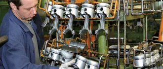
If the VAZ 2109 body is in good condition, then after the power unit has exhausted its service life, the owners are faced with the choice of a new engine. And since carburetor versions are no longer produced, installing an injection version will require a complete replacement of the standard electrical wiring.
To replace the motor you will also need a new wiring kit.
For reference: in a carburetor engine, fuel was mixed with air by an air flow, and only then entered the cylinders. In the injection system, it is supplied directly to the cylinders using electronically controlled injectors.
Car engine structure
The cars are equipped with four-cylinder, four-stroke carburetor engines of various cylinder capacities, with an in-line arrangement of cylinders and a camshaft located on the cylinder head.
The engine is specifically designed for transverse mounting in a front-wheel drive vehicle. Therefore, its layout and main dimensions were chosen such that it, together with the gearbox, could be placed transversely between the mudguards of the front wheels. Three unified engines with a working volume of 1100, 1300 and 1500 cm 3 are formed by a combination of three blocks of different heights and diameters of the cylinders, two cylinder heads with intake ports of different diameters, as well as two pistons differing in diameter (76 and 82), and two crankshafts shafts with crank radii corresponding to piston strokes of 60.6 and 71 mm.
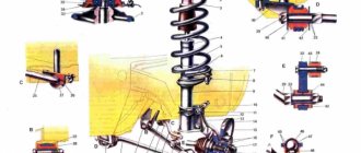
When assembled with the gearbox and clutch, the engine forms a single rigid unit - the power unit. It is installed on the car on three elastic supports. They perceive both the mass of the power unit and the loads that arise when the car starts, accelerates and brakes. Elastic supports absorb vibrations from a running engine and do not transmit them to the body, thereby reducing noise inside the car. On the other hand, elastic supports protect the power unit from sudden impacts when the car moves over uneven roads.
The car uses a three-point mounting scheme for the power unit, consisting of front, rear and left supports. The front and left supports have the same structure and consist of an outer steel ring and an inner aluminum bushing, between which there is rubber vulcanized to them.
The rear support is bolted from below to the underbody. It consists of an outer steel reinforcement and an inner aluminum sleeve, also separated by rubber. The rear suspension bracket is made of steel, forged, and is attached to the gearbox with bolts connecting the clutch housing to the gearbox housing.
Methods for tuning the power unit
There are many ways to improve engine performance. Before work, keep in mind that in case of an error you will have to completely change the unit. Each method of changing motor characteristics has its own advantages and disadvantages. Here are a few relatively safe tuning methods:
- Installing a zero resistance filter. Craftsmen often call this component “zero”. If you choose the right filter, the dynamic performance and motor power will increase by 5%. If you equip your car with a zero drive, then you will have to carefully monitor it and clean it in a timely manner. Otherwise, installing the element will be pointless and dangerous. A dirty filter poses a risk of engine damage. Focus on a price of 5 to 6 thousand rubles per filter. Instances that cost less will not work normally.
- Together with injection power units, it is often recommended to use direct-flow mufflers. This part should only be used in the gas exhaust system if you have carried out a thorough modernization of the engine. Another option when such a muffler would be appropriate: if the car has a turbo air injection system (additional compressor). The straight-through muffler will only affect power in conjunction with other upgrades. In other cases, installing it is a pointless waste of money. It will make the car noisier and a roar will be heard when driving.
- Another effective way to increase engine power is to install a sports range on the gearbox. At the same time, a 6th gear will be added, and the car will accelerate more dynamically due to a change in a number of gear ratios. The overall engine power will not change, but the dynamic characteristics will become noticeably better. At the same time, replace the piston group and install a more powerful engine. Deep reworking of the engine and gearbox will allow for a qualitative change in the power plant. You will feel the dynamics already when you first start the engine and accelerate. Such tuning will be expensive, but it will be worth it.
- Chip tuning is most often recommended for injectors. Using a simple laptop, a small amount of equipment and application programs, the ECU is configured. The advantage of this method is its low cost - you do not have to carry out mechanical work or interfere with the elements of the unit. If you make a mistake, it will be enough to replace the on-board computer. It will cost less than replacing an engine if another type of tuning fails. After flashing the ECU, you will immediately notice a change in engine performance.
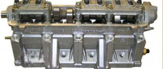
Cylinder block
All engine cylinders are combined together with the upper part of the crankcase into one common unit - a cylinder block cast from special high-strength cast iron. This arrangement ensures structural strength, rigidity, compactness and reduces engine weight. Coolant passages are made along the entire height of the cylinder block, which improves cooling of the pistons and piston rings and reduces deformation of the cylinder block from uneven heating.
The block cylinders are divided into five classes by diameter at 0.01 mm intervals. designated by the letters A, B, C, D, E:
| Class | Engine cylinder diameter 21081, 2108, mm | Engine cylinder diameter 21083, mm |
| A | 76,000-76,010 | 82,000-82,010 |
| IN | 76,010-76,020 | 82,010-82,020 |
| WITH | 76,020-76.030 | 82,020-82,030 |
| D | 76,030-76,040 | 82,030-82,040 |
| E | 76,040-76,050 | 82,040-82,050 |
The cylinder class is indicated on the bottom plane of the block opposite each cylinder. The cylinder and the piston mating to it must be of the same class. During repairs, the cylinders can be bored and honed to accommodate an increased piston diameter of 0.4 and 0.8 mm.
At the bottom of the cylinder block there are five crankshaft main bearing supports with thin-walled steel-aluminum liners. The upper and lower liners of the middle (3rd) main bearing are without a groove on the inner surface. The remaining supports have upper liners with a groove on the inner surface, and lower ones without a groove. Until 1988, the lower shells of these bearings also had grooves.
The bearings have removable covers 2, which are attached to the cylinder block with self-locking bolts. The holes for the crankshaft bearings in the cylinder block are processed together with covers, which ensures high accuracy, the correct geometric shape of the holes and their alignment. Therefore, the bearing caps are not interchangeable and, to distinguish them, have marks on the outer surface (see Fig. 6).
The middle support has slots for installing thrust half-rings 12 (see Fig. 6). holding the crankshaft from axial movements. A ceramic-metal half-ring (yellow) is placed on the back side of the middle support, and an aluminum-steel half-ring is placed on the front side.
The axial clearance of the crankshaft should be 0.06-0.026 mm. If the gap exceeds the maximum permissible (0.35 mm), it is necessary to replace the half rings with repair ones, increased by 0.127 mm. It should be borne in mind that the grooves located on one side of the half rings must face the thrust surfaces of the crankshaft.
From below, the cylinder block is closed with a stamped steel crankcase 37. The crankcase has a baffle to calm the oil. A gasket made of cork-rubber mixture is installed between the oil sump and the cylinder block.
The clutch housing is attached to the rear end of the cylinder block. The exact location of the crankcase relative to the cylinder block and the alignment of the crankshaft and the gearbox input shaft are ensured by two centering bushings pressed into the cylinder block.
Cylinder head
Cylinder head 27 is common to four cylinders. cast from aluminum alloy, has wedge-shaped combustion chambers. Valve guides and seats made of cast iron are pressed into the head. The seats, pre-cooled in liquid nitrogen, are inserted into the sockets of the heated cylinder head. This ensures a reliable and durable fit of the seats in the head.
A special non-shrink gasket on a metal frame is installed between the head and the cylinder block. The head is centered on the cylinder block with two bushings and secured to it with ten bolts.
To uniformly compress the entire surface of the cylinder head gasket, to ensure a reliable seal and eliminate subsequent tightening of the bolts during vehicle maintenance, the cylinder head bolts are tightened evenly without jerking in four steps and in a strictly defined sequence (see Fig. 7):
- 1st step - tighten the bolts with a torque of 2 kg cm;
- Step 2 - tighten the bolts to a torque of 7.08-8.74 kg cm,
- Step 3 - turn the bolts 90°;
- Step 4 - turn the bolts again by 90°.
In the upper part of the cylinder head there are five supports for the journals of the camshaft 17. The supports are detachable. The upper half is located in bearing housings 16 and 21 (front and rear), and the lower half is in the cylinder head. The mounting bushings for the camshaft bearing housings are located at the housing mounting studs. The holes in the supports are machined together with the bearing housings, so they are not interchangeable, and the cylinder head can only be replaced assembled with the bearing housings.
A KLT-75TM type sealant is applied to the surfaces of the cylinder heads mating with the bearing housings in the area of the outer camshaft supports. Install the bearing housings and tighten the nuts securing them in two steps.
- 1st step - pre-tighten the nuts in the sequence indicated on sheet 7 until the surfaces of the bearing housings touch the cylinder head, making sure that the mounting bushings of the housings fit freely into their sockets;
- 2nd step - finally tighten the nuts to a torque of 2.2 kg/cm in the same sequence.
Valve distribution phases During one working cycle, four strokes occur in the engine cylinder - intake of the combustible mixture, compression, power stroke and exhaust gases. These strokes are carried out in two revolutions of the crankshaft, i.e. each stroke occurs in half a turn (180°) of the crankshaft.
Engine structure of the VAZ 2109
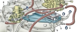
Engine VAZ 2109 top view:
1 — blocks with carburetor wires, 2 — fuel return hose, 3 — heater hoses, 4 — vacuum booster hose, 5 — fuel supply hose, 6 — clutch cable tip, 7 — ignition coil wire, 8 — radiator hoses, 9 — throttle linkage, 10 — air damper linkage, 11 — sensor wire for emergency oil pressure warning lamp
Engine VAZ 2109 bottom view:
1 - generator, 2 - right front support, 3 - engine, 4 - gearbox, 5 - starter, 6 - reverse light switch, 7 - extension, 8 - left front support, 9 - left front wheel drive, 10 - gearbox oil drain plug, 11 — rear support, 12 — gear shift rod, 13 — oil sump, 14 — right front wheel drive, 15 — engine oil drain plug
Removing the VAZ 2109 engine
Before removing the engine, disconnect the cable from the negative terminal of the battery. Drain the coolant from the cooling system, engine oil and gearbox oil. It is recommended to dismantle the VAZ 2109 engine assembled with the gearbox and using a lift to remove it downwards.
The procedure for performing engine dismantling work
Unscrew the mounting bolts and remove the crankcase protection
Remove the exhaust pipe from the muffler
Remove the air filter
Loosen the clamp and disconnect the brake booster vacuum hose from the engine inlet pipe
Unscrew the bolt and disconnect the ground wire from the clutch housing
Loosen the clamps and disconnect the hoses from the thermostat
Disconnect the high-voltage wire from the central terminal of the ignition distributor cover
Using a screwdriver, press out the spring clip and disconnect the block with low-voltage wires from the ignition distributor terminal
Loosen the clamp and disconnect the fuel supply hose from the fuel pump
Loosen the nuts on the end of the clutch release cable
Remove the cable end from the clutch release lever
Disconnect the block with the wire from the starter traction relay terminal
Unscrew the fastening nut and disconnect the wire from the contact bolt of the starter traction relay
Disconnect the block with the wire from the generator terminal
Unscrew the nut and disconnect the wires from the generator terminal
Disconnect the block with the wire from the carburetor shut-off solenoid valve terminal
Loosen the clamp and disconnect the fuel return hose from the carburetor
Loosen the bolt securing the choke rod to the choke control lever
Loosen the bolt securing the air damper drive rod shell to the bracket and disconnect the cable
Remove the accelerator cable spring clamp from the throttle valve drive sector
Remove the throttle actuator return spring
Remove the accelerator drive cable from the throttle valve drive sector
Unscrew the fastening nut and remove the accelerator cable bracket from the valve cover
Disconnect the block with the wire from the limit switch of the forced idle economizer
Disconnect the wire from the coolant temperature sensor
Disconnect the wire from the oil pressure sensor
Loosen the clamp and disconnect the heater supply hose
Loosen the clamp and disconnect the heater outlet hose
Loosen the clamp and disconnect the gear shift rod from the joint tip
Unscrew the fastening nut and disconnect the cable from the speedometer drive
Disconnect the block with the wire from the reverse light switch on the gearbox
Loosen the nuts securing the left and right braces to the suspension arms
Unscrew the three bolts securing the brace bracket to the body and move the left and right braces to a position so that they do not interfere with the removal of the power unit
Remove the cotter pin from the tie rod ball joint nut to the swing arm.
Unscrew the tie rod ball joint nut
Press the steering rod ball joint pin out of the strut swing arm using a special puller
Remove the two bolts and disconnect the ball joint of the suspension arm from the steering knuckle
Using a pry bar, press the shank of one of the inner CV joints of the drive shafts out of the gearbox and move it to the side
Insert a technological mandrel (for example, an old internal CV joint) instead of the hinge so that the side gear does not turn. After this, disconnect the second CV joint in the same way as the first
Unscrew the three mounting bolts and remove the clutch housing shield
Loosen the three bolts and nut securing the clutch housing to the cylinder block
Hook the engine onto the eyelets and pull the hoist ropes
Unscrew the two nuts securing the rear support of the power unit to the body
Unscrew the nut, slightly lift the engine and remove the bolt of the right front power unit support
Unscrew the nut and remove the bolt of the left front support of the power unit. Lower the engine onto stands, lift the car and remove the engine from under it. WARNING: Before lowering the engine, check that all wires and hoses are disconnected from the engine.
Installing the engine on a VAZ 2109
Installation of the VAZ 2109 engine is carried out in the reverse order of its removal. When connecting the front wheel drives to the gearbox, replace the retaining rings on the splined shanks of the inner joints. Do not install used circlips on the splined joints as this may cause the front wheel drives to disengage from the transmission while driving. After installing the engine on the car, adjust the air and throttle valves of the carburetor, the clutch drive, and the alignment angles of the front wheels.
Fill the cooling system with coolant, engine oil and gearbox oil.
Start the engine and check for fuel, oil and coolant leaks. Check oil pressure. Listen to the engine, it should run smoothly, without any extraneous noise or knocking. Check the operation of the indicator lamps in the instrument cluster.
What's inside the cabin
Replacing the power unit will also require replacing the interior wiring.
Many owners combine this process with replacing the instrument panel with a modern one:
- the “high” panel from the VAZ 21099 fits without modification;
- The “LUX” panel from the VAZ 2114 model is suitable with minor modifications.
The VAZ 2109 wiring diagram for the injector will also be needed to replace the interior wires
Tip: there are a lot of videos on the Internet that describe in detail the process of finalizing the panel. Read them all carefully before starting work on your car.
VAZ 2109 injector diagram: how it works
In 1997, they began producing 2109-20 cars, which are equipped with an engine with a distributed injection system (injector). This improves their efficiency, environmental and traction performance. Distributed injection is so called because fuel is injected directly into each cylinder by a separate injector.
Such a system makes it possible to somewhat reduce the toxicity of exhaust gases, as well as improve the driving performance of the 2109 car. Today, there are injection systems without feedback and with feedback. Both presented systems can include domestic and imported components. Each system has its own design, repair and diagnostic features.
I would just like to note the main principles of the design, normal operation, engine repair (if necessary) and subsequent diagnostics of the fuel injection system (the VAZ 2109 injector diagram is presented below).
The automotive fuel injection system, which has feedback, is used mainly on export VAZ 2109. The exhaust system of these cars is equipped with a catalytic converter for exhaust gases and an oxygen sensor. It provides feedback. Using an oxygen sensor, the oxygen concentration in already exhaust gases is monitored.
Next, the electronic control unit (ECU) of the vehicle, according to its signals, maintains the appropriate ratio of fuel and air, that is, one at which the special converter works extremely efficiently. The injection system, in which there is no feedback, is not equipped with a converter and an oxygen sensor.
Their function (regulating the concentration of CO in already completely exhausted gases) is performed by a CO potentiometer. They also do not use a gasoline vapor recovery system.
conclusions
We hope that our article will help you avoid annoying mistakes when servicing your VAZ 2109. And the proposed diagrams will help you understand the intricacies of the operation of electronic components.
Schematic electrical diagrams, connecting devices and pinouts of connectors
The VAZ-2109 car was produced at AvtoVAZ from 1987 to 1997. Years of production 21099: 1990-2004 - in Russia, 2004-2011 - in Ukraine. Here are colored wiring diagrams (for the injector and carburetor) with a description of all the elements for various modifications. The information is intended for self-repair of cars. Electrical circuits are divided into several blocks for ease of viewing via a computer or smartphone; there are also circuits in the form of a single picture with a description of the elements - for printing on a printer.
Like the entire car, its electrical equipment was at an average level, so owners of Nines should know the wiring diagram thoroughly for routine repairs with their own hands.
VAZ 2109 stove diagram: improvement options
The design and operation of the VAZ 2109 stove does not imply any complex procedures. However, the factory heater most often cannot distribute hot air evenly to the feet and onto the windshield. The modernization carried out on the VAZ-2114, contrary to expectations, could not solve this problem. However, there are no hopeless situations, and the presented diagram of the VAZ 2109 stove will help everyone who has the desire and time to solve this problem with their own hands.
In the process we will need:
- polystyrene foam and bitoplast;
- silicone or acrylic sealant;
- set of screwdrivers and keys;
- container for collecting coolant;
- sheet of copper or aluminum.
Maintenance
Repair manual for VAZ 2108, 2109, 2114, 2115 Wires and fuses
The operation of domestic cars has national characteristics:
- owners prefer to maintain and repair their cars with their own hands;
- This requires a detailed diagram of the main systems.
In the video presented in the article you can see which components and electrical circuits require constant monitoring by the owners.
https://youtube.com/watch?v=pxeWlEvePvI
Conclusions: cars of the VAZ 21093 family still serve today, delighting owners with their reliability. And any failures can be easily corrected yourself, having a detailed electrical wiring diagram at hand.
Let's get started:
- First you need to drain the coolant into a special separate container. Any liquid remaining in the radiator should be removed using a hose and funnel. Carefully remove the air ducts and, be sure to pay attention to possible misalignment of the holes that are located in the panel with the stove nozzles. If the misalignment exceeds 50%, you need to cut the interior heater.
- Next, having previously marked the connectors of the switches and light bulbs, remove the instrument panel. We disconnect the steering wheel, steering column trim and steering column switches. Next, we dismantle the heater: unscrew the 4 M10 nuts, disconnect the wire connector and all connectors on the heater body.
- Disconnect the radiator hoses and remove the heater valve cable latch. Next, carefully remove the heater, after unscrewing the two fan screws. Remove the radiator by unscrewing the three bolts. Be careful - there may still be coolant left here.
- Then make turbulators. These are special plastic spirals that increase the heat transfer of the radiator. “According to the rules,” they should be installed at the factory, but most often they are not. To make them yourself, you need to cut aluminum or copper plates, the width of which is 6 mm and the thickness is 1.5 mm. One side of such a plate should be clamped in a drill, and, at the same time, the other, using a vice, should be twisted into a spiral.
- Carefully inspect the bottom of the heater. Make sure there are no deformations, displacements, breaks or other defects. Then disassemble the stove by separating the body into two halves. To do this, use a screwdriver to open the latches and then unscrew the screw under the central nozzle. Remove the damper control levers.
- Carefully inspect the inside surface of the stove. If the foam has come loose, carefully glue it back, you can add strips of bitoplast. The housing should be made as airtight as possible. Adjust the center shutter.
- Before you begin assembling the heater, be sure to lubricate the places where the dampers are attached with a special grease. At the same time, when connecting the halves of the case, apply silicone or acrylic sealant to the connector. The heater should be assembled in the reverse order of disassembly. If there is deformation on the bottom wall, fill the gap with sealant.
- There should be no gaps between the stove body and the radiator. In the places where the housing is connected to the radiator, bitoplast should be glued. Next, you need to balance the fan impeller by winding wire around the blades. The wires must be routed through a special rubber plug located in the heater housing.
- Be sure to adjust the travel of the dampers. You need to be guided by the fact that the levers should always be clearly fixed in their extreme positions. Adjustment must be carried out by selecting the positions of the braid. Next, adjust the stove tap. You should choose a position in which the tap will not close completely.
- It is necessary to lubricate the hoses and radiator tubes with sealant before installing them. New clamps should be used. When the assembly is completed, you have filled in the coolant and warmed up the engine, you should tighten the clamps again. Before installing the instrument panel, you need to glue foam and bitoplast to the inlet holes of the nozzles.