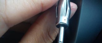
A friend and I once went shopping, nothing foreshadowed trouble... We were looking for either a seal for his viburnum, or some other small thing. I suddenly remembered how I recently watched the guys install pneumatic horns, and they sound decent! I wanted the same one for myself, because the standard signal is quiet and inconspicuous anyway. I decided to ask, one elderly man brought me to his stall and showed me a huge selection of beeps. Of these, I liked this one the most.
I couldn’t find any clear instructions, many of the manuals just contain a couple of photos and diagrams, so I decided to write in detail how I did it myself. I hope this post will be useful to someone who doesn’t know much about it and wants to stage it.
The kit included the pipe itself, a hose and a small compressor. No papers, nothing went through. There was no doubt that it was made in China, but the price was reasonable, and so was the quality (nothing fell apart during assembly and works fine). Having looked at the drive, and surfing the Internet anyway, I came across 2 types of connection - through a relay and from a standard bell. At first I didn’t want to do it through a relay - it was too complicated, but I decided to do it anyway. I bought a holder with a 30A fuse, found 2 meters of copper wire, gathered my courage and started assembling it. I found several relay diagrams, here are some of them:
One of the horn options is a pneumatic signal on a car, which has both its pros and cons. Previously very common, it is much less common on modern machines. However, many car enthusiasts still want to install such a device for themselves. You will learn how to do this and much more about pneumatic signals in the article.
Scion xB vidulus › Logbook › Installing an air signal
In search of a replacement for the standard signal, many options were listened to (I wanted a low tone), but the choice was made after the next wild situations on the roads:
1. Smoothly dull and without a turn signal, exit from the right lane to the left at a speed of 60 km, when you are calm you travel 120 km.
2. When turning at intersections, immortal pedestrians stand on the road a meter from the curb.
3. Slowly walking pedestrians across the road with a phone on their ear or headphones.
I bought this pipe at the market
The corrupt watchman from the women's bathhouse took out my tights. Having suppressed the burning desire to try on women's sweatpants, I concentrated on the pipe.
Tights are a must
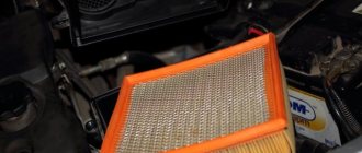
We put the pipe on the bell to prevent any insects and debris from getting in: midges, fluff, pigeons.
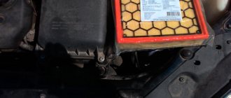
I spent half an hour looking for a regular signal. Ended up under the left headlight. Taking the radiator grill out of the bumper, I got to the tablet.
I applied graphite grease to the bolts.
Level control relative to the body and horizon.
We cover all places with construction silicone.
PS...If you press the horn for more than three seconds, the 15A fuse burns out (I think it’s not necessary to press that much), set it to 20A, that’s enough for fa-fa. I think I need to install a relay (I don’t know how yet)
I think I can use the standard signal through a button in the cabin ("grandma please come in" mode)
Initially, I thought of bringing the pipe through the button into the cabin, attaching it to the automatic transmission handle, installing the button on the floor under the left foot, but in the situations described above, until I find it, it will no longer be needed.
mode test “Who are you? Bye Bye":
Source
Lada Priora Sedan › Logbook › Installation of air horn (very detailed + many photos)
A friend and I once went shopping, nothing foreshadowed trouble... We were looking for either a seal for his viburnum, or some other small thing. I suddenly remembered how I recently watched the guys install pneumatic horns, and they sound decent! I wanted the same one for myself, because the standard signal is quiet and inconspicuous anyway. I decided to ask, one elderly man brought me to his stall and showed me a huge selection of beeps. Of these, I liked this one the most.
I couldn’t find any clear instructions, many of the manuals just contain a couple of photos and diagrams, so I decided to write in detail how I did it myself. I hope this post will be useful to someone who doesn’t know much about it and wants to stage it.
The kit included the pipe itself, a hose and a small compressor. No papers, nothing went through. There was no doubt that it was made in China, but the price was reasonable, and so was the quality (nothing fell apart during assembly and works fine). Having looked at the drive, and surfing the Internet anyway, I came across 2 types of connection - through a relay and from a standard bell. At first I didn’t want to do it through a relay - it was too complicated, but I decided to do it anyway. I bought a holder with a 30A fuse, found 2 meters of copper wire, gathered my courage and started assembling it. I found several relay diagrams, here are some of them:
I did schemes 1 and 2, they are the same, just drawn differently. When I had already decided on the scheme, I began to do everything. First I removed the old call.
And here, by the way, is a new buzzer.
I thought for a long time about where to put the pipe, of course it is big and loud, but it also takes up a lot of space. I decided to leave it for later and started doing the wiring. There were 2 contacts coming out of the old signal, but in a plug I didn’t need. I carefully cut the plug out of plastic, trimmed it here and there, bent it here and there, and took out 2 plugs.
At first I wanted to connect the contacts using construction adapters, I even sharpened and tried them on.
Then I proceeded to connect this case to the relay. As luck would have it, I didn’t find any terminals, or any connectors, and the bumper had already been removed and I didn’t want to retreat... So I used a soldering iron and heat shrink with electrical tape. I started attaching this thing to the relay. To “+” from the battery to the relay (the distance is small), I connected the fuse holder with its wire, which was quite enough. From the “+” and “-” of the factory horn I ran a wire in 2x1.5 insulation and measured approximately 1.5 meters. From “+” the relay started a 1x2.5 wire, having previously released it from thick insulation (before that there were 2x2.5 in thick insulation). Also about 1.5 meters. Having connected everything according to the diagram on the relay, we got something like this.
On the other side of the fuse holder I soldered a homemade power terminal made from shelf fasteners using a grinder and a drill =)
Then he wrapped the whole thing with a bunch of electrical tape and put it in a plastic corrugation.
And proceeded to connect the compressor.
I decided to throw the minus onto the body, but there were no terminals, so I made another “terminal” from the remaining part of the fasteners. Since the soldering iron was at hand, I decided to abandon the plastic connectors and also solder the wires from the factory bell, and again heat-shrink everything.
Next to the battery I found a place for the relay
Before attaching the compressor, I put cellophane on it from under the pipe, it was already in the morning, because I had been fiddling around for half the night, so it was only in the morning that I realized that like a compressor it would suck air through the cellophane, then I fixed everything and here is the result:
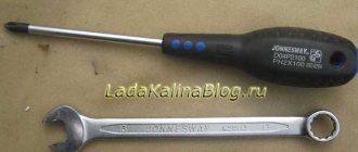
I would also like to say that I am extremely pleased with the result, it buzzes as it should. It took quite a lot of time, I started in the evening and finished in the morning. True, most of it was spent searching for the key for 13, which “just lay here” and various solders and heat shrinks =) Regarding the connection via a relay... I don’t regret the time spent (especially the money), because during the connection process I encountered a problem, I threw the compressor on the factory contacts, just try the sound and check the functionality, after a couple of presses the fuse burned out. From the factory it was set to 10A and it burned out, this once again indicated to me that my choice was correct))
Here is a video of the sound, although it was not possible to convey all the sound, in real life the buzz is louder.
I soldered everything with a regular soldering iron, used solder with rosin and soldering flux (a very good thing!).
The price turned out like this: Pneumatic horn - 650 rubles Holder with fuse - 30 rubles Relay - was in the glove compartment He already had a set of heat shrink - 30 rubles Plastic corrugation - 20 rubles
In total, all the fun turned out to be 730 rubles. In my opinion they are worth it!
I hope the article turned out to be quite detailed and informative, it will help someone!)
Source
Refinement of the siphon
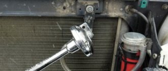
Before assembling the structure, it is necessary to modify the siphon; this modification must be taken seriously. Strictly adhere to the proposed revision scheme. You need to shorten the central pipe of the siphon with your own hands so that it protrudes above the plane of the outer pipe by 1.5-2 mm. Using a ruler, we mark the place of the cut and use a metal saw to cut off the excess part. We carefully sand the cut area with emery cloths to reduce the grain size. You should get a smooth, even surface - this is a must.
Inner pipe
The edge is smoothed
Difficulties in manufacturing were caused by the method of attaching the rubber sound membrane. There are two ways to implement this. The first way is simple, attach the membrane to the surface of the siphon without further modification of the latter. The second way is complicated, modify the siphon and install a protective cap over the membrane.
First way
used in the design of the device. If you stretch the rubber and hold it tightly against the outer casing, you can blow into the side hole with your mouth and get a sound. So all available rubber materials were tested; the best effect was obtained from a piece of rubber from a torn swimming cap. There was no denser material at hand. When used permanently, the membrane can be secured with twine and electrical tape. The disadvantage of the first way is that part of the sound will be radiated outward bypassing the output pipe and the membrane may be damaged.
Second way
. Various siphons and fastening methods were used, but it was not the original method that won. To avoid premature rupture of the membrane, the external thread on the siphon is completely cut off. The thread on the cap is covered with tape. There are holes cut in the cap itself; the size and number of holes affects the frequency and volume of the sound, and for denser rubber the number of holes may be small. The cap without a membrane should be freely removed from the siphon. See photo.
Hyundai Getz SuperCar › Logbook › Installing an air signal
Hi all!
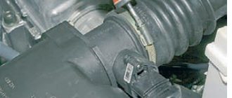
I have long wanted to install an air signal for myself. The choice fell on Horn Tech with one pipe, because... I heard the sound of 2 and 3 pipes, I didn’t like it, firstly - it’s quiet (maybe, of course, the compressor is not working), and secondly, the sound is of a different tonality, like a melody, which is only suitable for a friendly greeting, and not for “Where are you going” ! I read a lot on the Internet about installation, collected my thoughts and decided to post a short photo report on installing an air horn on a Hyundai Getz. The first question was one and the most important - where to stick this same compressor and pipe. With higher and larger class cars, everything is clear - there is more space, maybe under the bumper, maybe behind the radiator grille, maybe somewhere else. But this did not happen with Getz. Having climbed around the entire engine compartment with a pipe, I found, in my opinion, the most suitable place.
Four holes and stood up like a native! The wires are successfully hidden in the rubber seal.
Then the second question arises: Is it worth bothering about connecting the signal through a relay and will it be better? It's worth it! I'll try to explain why! When connected directly (i.e. the compressor is connected directly to the standard signal chip). In this case, the current to the compressor goes through the standard system (through relays, fuses that are not designed for this compressor, and it also creates an increased load on the signal button), and therefore, I believe, the signal sounds weaker! It was decided to mess around a little and connect it via a relay. A 4-pin relay and a socket for it, and wires, respectively, were purchased.
If connected via a relay, the situation is slightly different. Current passes through contacts 85 and 86, thereby exciting the electric/magic. the magnetic field in the relay, which thereby connects contacts 87 and 30 through a pusher, which in turn connect the compressor directly to the battery, which minimizes voltage losses.
As I have promised! Video to the studio!
Source
Types of car horns
Pneumatic signals
They work on the same principle as the old horns from the days of horse-drawn carriages: a compressor supplies compressed air through a pipe, causing vibrations. All copies are in the same price category, while differing in design. Most often this concerns the shape of the horn pipe.
Pneumatic signals can have a power of up to 125 dB, and their frequency range is located at several required levels at once. This is achieved by placing four “horns” (in some cases less). Thus, the lowest signal plays at a frequency of 320–415 Hz, and the highest sound can reach up to 810 Hz. To power this orchestra, the compressor needs a pressure of at least six atmospheres. In this case, the sound of the horn will form a real melody, but this requires programming the device and a lot of space under the hood.
Electromagnetic beeps
In such equipment, the main element is an electric magnet, which is connected to the membrane. The breaker connects the current source to the core winding, and it, in turn, to ground using a signal button. Activation of the latter causes the core rod to perform oscillatory movements, which lead to vibration of the membrane. These signals differ according to the criterion of the sound emitter.
Disc horns
They have a collapsible or one-piece design. The latter allow you to save several centimeters of space. The type of execution allows you to install open and closed, respectively, in plain sight or under the hood. Standard signals are designed in a similar way, which allows you to install “pancakes” without much effort. The device can be two-tone, but single-tone ones can also be configured by combination, resulting in a synthesis of a high-frequency signal (420–440 Hz) and a simple one (335–350 Hz).
This type is more difficult to install due to the curved shape of the pipe and larger size. Signal power - 118 dB, frequency - 510 Hz. These kind of gramophones are known for putting a lot of pressure on the eardrums. A two-tone "snail" may have a relay that supplies electricity alternately to each of the windings, allowing it to produce a melody.
Chevrolet Lanos Good bye may love › Logbook › Fa-Fakalka (air pneumatic signal)
Hello to all readers of my blog!
Holms96 You also have a steam locomotive whistle) I shouldn’t have installed it