The Calina and Kalina 2 models have different headlight designs, so replacing the lamps in them has certain differences, and we will describe which ones in this article. Replacing light bulbs yourself will not cause you any problems. Therefore, there is no point in turning to the service for help.
On Kalina 2 from 2013, to replace the lamps in the left headlight unit, you need to move the air filter to the side so that it does not interfere. There will be nothing in the right headlight block that will prevent replacement.
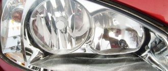
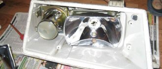
Review of block headlights Lada Kalina 2
Above is a photo of the left headlight, everything on the right is identical. 1 - ventilation tube; 2 — low beam section cover; 3 — cover of the high beam section; 4 — light beam regulator in the vertical plane; 5 — lamp socket for side light and daytime running light; 6 - electrical connector; 7 — regulator of the light beam in the horizontal plane; 8 - turn signal lamp socket
Tail lights and lamps
The following elements are used as brake light lamps in Kalina-2: lamps with a P21W socket and a transparent bulb. Replacing such an element will not be difficult.
Brake light bulb, VAZ-2192/2194
The rear turn signals are equipped with the same bulbs as discussed above. Their bulb is colored yellow (type PY21W).
The reversing light in the hatchback is provided by a lamp of the following standard size - R10W. If we talk about the station wagon, they use lamps of a different type - W16W. They do not have a metal base.
These are the reversing lamps
In conclusion, we note the following: the light of the side and fog lights in the rear lights is provided by a combination lamp. Its standard size is P21/4W. Good luck with your choice!
It is important to know! When performing any actions with electrical equipment, you must first disconnect the negative terminal of the battery. The terminal fastening is unscrewed with a 10 mm wrench.
Instructions for replacing lamps on Kalina 2 Cross
Low beam
Carefully remove the rubber boot from the low beam (it is larger in size)
Disconnect the socket from the light bulb
Next, press the spring clamp and remove it from the clamps to the side and move it away
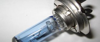
We remove the burnt out one and install a new lamp. The H7 Osram lamp is installed from the factory; if you want to put a brighter light, you can choose a Philips H7 +30.
We reassemble in reverse order.
High beam
Remove the rubber boot from the high beam
Disconnect the block from the lamp. There is only a + wire on the lamp.
Press the spring clamp of the lamp and move it to the side
We take out the old lamp and replace it with a new one. Be careful when installing, it can only be installed in one position.
We also perform assembly in reverse order.
How to change a DRL lamp
Take the cartridge and turn it counterclockwise.
Next, remove the socket from the socket, remove the old lamp and install a new one. Toshiba lamps are installed from the factory; it is impossible to buy them in retail stores, so we choose an analogue.
Turn signal lamp
By pressing lightly, turn the cartridge counterclockwise and remove it from the socket
Press the lamp and turn it counterclockwise, pull it out of the socket
We take a new PY21W lamp and install it in the socket.
This completes the lamp replacement.
When replacing low and high beam lamps, touching their bulbs is prohibited! This will lead to rapid failure of the lamp. The rest of the lamps are incandescent, and this does not threaten them.
Watch a video on changing light bulbs.
For 15 years I have been repairing various types of cars, including brands such as VAZ, UAZ, Chevrolet, Mazda, Kia and many others. Everything related to the gearbox, engine or chassis. You can write me your question below in the comments and I will try to answer it in detail.
On the territory of the Russian Federation, amendments to the rules of the road (TRAF) have been in force for more than 8 years, according to which a moving vehicle during daylight hours must be indicated by low beam headlights, fog lights (FTL) or daytime running lights (DRL). Using headlights and fog lights for these purposes has a number of disadvantages. Therefore, drivers prefer to buy ready-made running light modules and install them in their cars themselves. How to properly connect daytime running lights so that their operation is safe and does not contradict current laws?
The lamp is not fixed
But then other problems arose. There are latches on the base that help it stay in the socket and not fall out. They are also located as on a glass light bulb. But when you insert it into the cartridge, then, apparently, the contacts are not pressed somewhere. The lamp for Kalina 2 only worked for daytime running lights; it did not light up on the side lights. It is not clear what this is connected with.
When you start to pull it out with the lights on, somewhere at the end it lights up. You insert it back - there is no contact, it’s unclear.
How to tune Lada Vesta headlights?
The latches are slightly different, and this is enough to prevent contact. You can, of course, sharpen, adjust and ensure that everything functions as expected. But somehow I don’t want to buy new light bulbs and then tinker with them and redo them.
How to connect a DVR in a car with your own hands?
This lamp for Kalina 2, as well as for Granta in DRL mode, works well, the light is bright. But they don’t work without soldering - they don’t have the same polarity as standard light bulbs. You need to take this into account, resolder it, and everything will be fine. I'm happy with the LEDs, except for the base. Was it really impossible to do a normal fixation? After all, now Chinese goods are not all bad - many good things can be ordered from China for your car.
Lada K alina 2 . REPLACING LAMPS - PART 2
To replace the turn signal lamp
do the following.
1. Open the hood and place it on the stop.
5. Install a new turn signal lamp into the headlight unit.
To replace the side light bulb and daytime running light bulb
do the following.
4. Install a new side light and daytime running light bulb into the headlight unit. To replace the fog lamp bulb, perform the following steps.
Replacement of left headlight bulb shown
. The lamp in the right headlight is replaced in the same way.
1. Remove the front fender liner (Removing and installing mud flaps and wheel liners”, p. 246).
USEFUL ADVICE The fender liner does not need to be completely removed; just unscrew the screws of its front fastening and bend the edge of the fender liner enough to gain access to the lamp.
6. Install the new lamp in the reverse order of removal.
To replace a rear light bulb
perform the following operations. The work is shown using the example of a turn signal lamp; other lamps are replaced in the same way.
4. Install the new lamp into the taillight and all removed parts in the reverse order of removal.
Any electric lamp, excluding xenon, contains an incandescent filament in its design. This filament burns out over time, and the lamp has to be replaced. The text lists the types of lamps installed in optics, as well as in the illumination modules of Kalina-2 cars (VAZ-2192/2194). For station wagon and hatchback, the kits are slightly different.
The nuances of turning on running lights
The basic requirements regarding installation, technical parameters and connection of navigation lights are listed in paragraph 6.19 of GOST R 41.48-2004. In particular, the electrical functional circuit of the DRL must be assembled in such a way that the running lights turn on automatically when the ignition key is turned (the engine starts). In this case, they should automatically turn off if the headlights are turned on.
Clause 5.12 of this standard states that headlights (FGS) should be turned on only after the lights are turned on, with the exception of short-term warning signals. When connecting DRLs yourself, this feature must be taken into account.
Correct connection of DRLs is not limited to a well-thought-out functional diagram. It's time to think about the stabilization unit for LEDs. In the running lights themselves, resistors act as a current limiter; however, due to voltage drops, resistors cannot limit the current to the same level. That is why a voltage stabilizer in the running lights connection circuit is extremely necessary. Otherwise, the service life of LED DRL modules is significantly reduced due to constant changes in on-board voltage. Some car enthusiasts claim that it is possible to connect running lights without a stabilizer.
Connecting and installing an LED driver is a waste of time, because the DRLs on LEDs shine regularly for months without any stabilization...
However, this statement is easy to dispute. The fact is that with each voltage surge, more than 12 V appears on the LED module, the forward current through the LEDs exceeds the nominal value, which leads to overheating of the emitting crystal. The brightness of the LEDs decreases, such DRLs will no longer be able to fulfill their immediate task - to warn oncoming drivers from afar, and over time they will begin to flicker and fail.
Using LED DRLs without a voltage stabilizer means spending at least several hundred rubles every year on new modules and wasting time replacing them.
For ease of understanding, the circuits below are shown without using a stabilizer.
Design Features
Kalina's light is not technologically advanced, since the optics use classic halogen elements. From the factory, the modules contain parts from Philips or Osram with the Long Life prefix, which means an increased service life.
The Kalina lighting system in the old and new body differs in the location of the modules, shape, and size. The elements used in optics are:
- turn signals – PY21W;
- low beam – H7/55 W;
- high beam – H1/60 W;
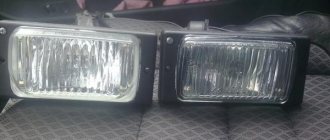
- fog lights – H11/55 W;
- Dimensions – W5W.
In modifications of Kalina since 2013, running lights have been added from the factory, which use parts with the index W 21/5 W.
Some car owners cannot fit their hand into the cramped space between the TV and the air filter housing. In this case, the Kalina intake system is dismantled or the radiator grille and headlight are removed.
Switching on through dimensions or low beam
The second version of the DRL connection diagram involves using the power circuit of the side light bulb. To do this, the positive wire from the running lights is directly connected to the “+” from the battery. In turn, the negative wire is connected to the “+” of the side light, which is currently electrically neutral. As a result, the following current flow path is formed: from the “+” of the battery through the LEDs to the size, and then through the light bulb to the body, which serves as the minus of the entire circuit. Due to the low current consumption (tens of mA), the LEDs begin to glow, and the lamp spiral remains extinguished. If the driver turns on the side lights, then +12 V appears on the positive side of the side lights, the potentials on the DRL wires are equalized and the LEDs go out. The circuit goes into normal mode, that is, current flows through the side light bulbs.
This circuit solution has several disadvantages:
- running lights remain on when the engine is turned off, which is contrary to current regulations;
- the circuit will not work if LEDs are also installed in the dimensions;
- the circuit will not work correctly if the DRLs contain powerful SMD LEDs, the rated current of which is comparable to the current of a light bulb;
- For safety reasons, an additional fuse must be installed.
This connection method can be improved by connecting the positive wire of the LED module not to the “+” of the battery, but to the “+” of the ignition switch, thereby eliminating the first drawback. Some motorists use schemes for turning on running lights through a low beam lamp. That is, when the low beam is turned on, the DRLs automatically go out, but in other cases they work. In addition to the above disadvantages, this method does not comply with GOST R 41.48-2004 and traffic rules.
When parking a car at night, side lights are used to indicate it; the use of DRLs is prohibited.
How the work is carried out
Let's figure out how to replace the low beam light bulb on Kalina with your own hands, the process is quite simple and, by and large, does not require any special devices, you only need your hands. But still, the tool may be needed at the preparation stage.
Preparation
It is important to ensure a comfortable and safe working environment, so remember the following:
- The work can be done anywhere - even in the yard near the house, but it is advisable to go to the garage. There you can not be afraid of precipitation and, if necessary, find this or that tool.
- First of all, the hood is opened and the terminal is removed from the battery. We remind you of this in every review. Therefore, make it a habit to de-energize the system when working with electrical equipment to prevent short circuits and electric shock.
- Further preparation depends on what engine is installed in your car, you need to provide access to the rear of the headlight housing, and for this you need to disconnect the expansion tank on the left, and the options on the right may be different. Therefore, be guided by the situation and decide for yourself. What needs to be removed and what should not be touched.
Connection via a 4-pin relay from a generator or oil sensor
The following two methods have a common basis and imply the operation of daytime running lights only after the engine is started. The circuit for switching on DRL from the generator is based on switching a four-contact relay and a reed switch. The DRL relay contacts are connected as follows:
- 30 – to the positive terminals of LED modules;
- 85 – to the positive wire to the dimensions;
- 86 – to any reed switch output;
- 87 and the second terminal of the reed switch - to the “+” of the battery.
After checking the reliability of all contacts, proceed to setup. To do this, start the engine and, by moving the reed switch near the generator, achieve its activation and a stable glow of the DRL. Then the reed switch is hidden in a thermal tube and fixed in the found place using nylon ties.
At the moment of starting the engine, and then the generator, the contacts of the reed switch and relay close, supplying power to the LED running lights. In this case, the side lamps remain turned off, since the current through the relay coil is small to light them.
In the absence of a reed switch, you can power the DRL from the oil pressure sensor. In this case, pin 86 is connected to the oil pressure lamp. The rest of the circuitry is duplicated. Both schemes have a common drawback. They cannot be used if LEDs are installed in the dimensions.
Selection rules
When you choose running lights for your Kalina, follow a few rules:
Products from Osram, Hella or Philips satisfy the above criteria. Running lights for Kalina cost from 2 to 15 thousand rubles. The price depends on a number of their characteristics, configuration and company. To study the shape and brightness of the DRLs before purchasing, look at the photo of the optics on the car.
Despite the opportunity to use the services of specialists when installing optics, there are also kits on sale, thanks to which you can install running lights on your car yourself. This includes:
When choosing, you should carefully read the markings on the lamps
Additional equipment includes a device that enables activation and deactivation of the running lights on the Kalina during engine startup and shutdown.
Each kit is supplied with connection instructions, but optics originally intended for foreign-made cars may require adaptation to a domestic car.
Connection via 5-pin relay
Now it's time to learn how to connect running lights via a five-pin relay. The scheme is the most universal, and was assembled to eliminate the disadvantages of previous options. First, about connecting the relay for DRLs:
- 30 – to the positive terminals of LED modules;
- 85 – to the positive wire of the side lamp;
- 86 – on the car body;
- 87a – to “+” from the ignition switch;
- 87 – do not connect (isolate).
The circuit with a five-contact relay works as follows. When you turn the key, +12 V is supplied to the DRLs, thereby turning them on. If you turn on the side lights or headlights, the relay will open contact 87a and close inactive contact 87. As a result, the DRLs will go out and the side lights will turn on. The circuit fully complies with the requirements of GOST and traffic regulations and can work with side lights even based on LEDs.
However, the circuit still has one negative point - the DRLs will turn on immediately after turning the ignition switch. That is, if you turn the key in the ignition but do not start the car, the DRLs will light up.
Despite the existing drawback, the circuit is quite successful, but in order to correctly connect the DRL via a five-pin relay, you will need to supplement the circuit with a voltage stabilizer.
This switching option is interesting because the path of current flow through the running lights is independent. This allows you to install light sources of any type and power in headlights and DRLs.
Tail lights and lamps
The following elements are used as brake light lamps in Kalina-2: lamps with a P21W socket and a transparent bulb. Replacing such an element will not be difficult.
Brake light bulb, VAZ-2192/2194
The rear turn signals are equipped with the same bulbs as discussed above. Their bulb is colored yellow (type PY21W).
The reversing light in the hatchback is provided by a lamp of the following standard size - R10W. If we talk about the station wagon, they use lamps of a different type - W16W. They do not have a metal base.
These are the reversing lamps
In conclusion, we note the following: the light of the side and fog lights in the rear lights is provided by a combination lamp. Its standard size is P21/4W. Good luck with your choice!
It is important to know! When performing any actions with electrical equipment, you must first disconnect the negative terminal of the battery. The terminal fastening is unscrewed with a 10 mm wrench.
DRL control unit
The most reliable and simplest option is to connect DRLs without a relay, but using a special running lights control unit. It ensures that the DRL turns on after starting the engine, guarantees safe operation, protects against overloads and can be installed on cars with any type of lamps, including LEDs.
Unfortunately, among the variety of industrially manufactured DRL units, the vast majority do not comply with GOST and have mediocre build quality.
This applies, first of all, to products from AliExpress, which do not meet the requirements in almost all respects.
Among all the diversity, only 2 options can be noted: the Russian DayLight+ DRL control unit and German products from Philips and Osram. The DayLight+ control unit was developed by Russian radio engineer Fedor Isachenkov, taking into account all the features of the vehicle’s on-board network and has a number of positive aspects:
- there is built-in voltage stabilization;
- full compliance with GOST;
- the maximum long-term load power is 36 Watts (significantly less is required for DRLs);
- simplest connection diagram.
In addition to the points described above, the DayLight+ unit is universal and is suitable for all cars with an on-board 12-volt network, and also has good build quality and a high degree of protection from moisture and dust.
German products from Philips and Osram also have all the above-described advantages of the DayLight+ unit, however, German control units are supplied only together with daytime running lights and are more expensive.
The daytime running light bulbs have burned out. They served for 2.5 years, I think this is a good period. For comparison, I have already changed the low beam several times. It so happened that 2 lamps burned out with an interval of a week. So, I bought 2 Philips W21/5W W3x16d (12V 21/5W) light bulbs for 115 rubles each. The right lamp is much easier to change than the left one, since the ABS control unit does not interfere there.
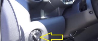
We turn off the engine and remove the ignition keys. We put our hand in here, as shown in the picture, and rotate the lamp counterclockwise (top towards the motor) 45 degrees. Since I changed it in the cold (most likely because of this), the base was difficult to turn.
Replacing the right DRL Kalina 2
Then we proceed to the left DRL, it becomes more and more difficult, since there is not enough room to crawl. There are videos on the Internet where people remove the air filter, but this is not necessary. In addition, in the cold, plastic becomes brittle and can be broken.
We put our hand under the antifreeze return line.
Replacing the left DRL Kalina 2
Be careful not to damage your hand or wires or get burned if you decide to change the lamps when the engine is hot over 90 degrees.
After jumping around in the cold for 15 minutes, I tried to adjust the key to 10 so that I could turn the base using a lever.
Using a 10mm key, the base turned instantly.
By the way, the base with the new lamp fit into place normally.
Daytime running lights (DRLs) are designed to improve visibility of the vehicle from the front during daylight hours. On modern cars, for example, Lada Granta, Kalina, XRAY DRLs are installed from the factory. Other models Lada Priora, Vesta, Largus or Niva do not have DRLs, but you can install them yourself..
Before you start repairs
Before changing the low beam lamp on Kalina, you need to check the integrity of the on-board network:
- When understanding the causes of failure of any component of electrical equipment, you should first make sure:
- the fuse is in good working order;
- look at the circuit connectors, which should be well secured;
- Often the causes of electrical equipment malfunctions are the oxidized ends of the pads; their terminals should be cleaned.
- Take a good look at the places where the car is connected to ground. Often, due to the lack of reliable fastening, disturbances in the functioning of electrical equipment occur, so replacing low beam lamps on Kalina may not always help with the problem.
- the equipment will help to find faulty places in the electrical circuit;
- is a combined electrical measuring device.
There are several types of such devices:
- digital, equipped with a liquid crystal display;
- analog;
- universal models, characterized by the presence of a liquid crystal screen and a dial indicator.
Multimeter
During repairs, we recommend using a digital device (in other words, a multimeter), which is small in size.
To check de-energized circuits, the device should be switched to ohmmeter mode:
- if you need to measure very low resistance (for example, within a few Ohms), you should enter a clarification - from the obtained indicator we subtract the internal resistance, the electrical resistance of the probes and multimeter wires (within 0.07 Ohms);
- to determine a more accurate value, the device is switched to the mode for measuring low resistance values (up to two hundred Ohms), then the ends of the probes should be short-circuited.
To check live circuits, the multimeter should be switched to voltmeter mode (the limits of permissible measurements are up to twenty volts). The device is capable of measuring the current consumed by electrical equipment of vehicles (up to ten amperes).
In cases where the task is to find out whether or not there is voltage in a certain section of the circuit, without resorting to measuring the value, you can use a special indicator light designed for twelve volts. You can also use a test lamp.
You can make it yourself:
- you will need a car lamp with a power of up to 4 W;
- take 2 two wires, the length of which is from 500 mm;
- solder them to the lamp.
The car is equipped with 2 headlights, in which halogen lamps are mounted. There are two screws on each to adjust the light beam. They make it possible to change its direction in the vertical and horizontal planes.
Requirements for DRL according to GOST
Functional electrical diagram:
- DRLs should turn on automatically when the engine start/stop control is turned to the “on” position.
- It must be possible to activate and deactivate the automatic DRL operation without the aid of a tool.
- DRLs must turn off automatically when the headlights are turned on, except when the headlights are turned on for a short period of time to signal road users.
Self-installation of DRLs is considered as making a change to the design of the car. If the vehicle is not equipped with DRLs, either low beam headlights or fog lights should be used instead during the daytime.
DRL connection
How to connect daytime running lights so that they meet GOST requirements? There are many such connection methods. We decided to publish the simplest of them, which uses only one 5-pin relay. The general connection diagram for DRLs is as follows:
It is worth noting that using the connection points from the diagram, all connections are made in the engine compartment; it is not necessary to lay wires into the car interior. Electrical diagrams may also be useful (Lada Priora, Lada Kalina, Lada Granta, Lada Largus)
Lighting control modules MUS 50.3769, 521.3769, 522.3769, 58.3769, 582.3769 are designed for switching electrical control circuits for external lighting, front and rear fog lights, adjusting the level of illumination of controls and instruments, and controlling the angle of the light beam of automobile headlights.
Lighting control module MUS 50.3769 for Lada Granta, VAZ-2190, Lada Kalina FL, VAZ-2192, VAZ-2194, characteristics, contact assignments.
The lighting control module MUS 50.3769 is connected to the electrical equipment system of Lada Granta and Lada Kalina FL using block 1118-3724500.
Main characteristics of the lighting control module MUS 50.3769 for Lada Granta, VAZ-2190, Lada Kalina FL, VAZ-2192, VAZ-2194.
Rated voltage, V: 12 Rated load: - Inductive: 110 mH; 0.5 A contact 56, 50 mH; 0.25 A contact 1 - Lamp: 10 A contact 58 and contact 3, 5 A contact 4, 2.5 A contact 2 Color of the viewing surface: black Color of symbols: white Color of symbol illumination: light green Dimensions, mm: 70x110x64 Weight, no more, kg: 0.2
Numbering and assignment of contacts of the lighting control module MUS 50.3769 for Lada Granta, VAZ-2190, Lada Kalina FL, VAZ-2192, VAZ-2194.
G - not used. 56b - not used. 58b - not used. 31 - Mass. Xz - +12 Volts from terminal “15” of the ignition switch. 56 - to low beam lamps. 1 - Ground (signal for turning on side lights from the central body electronics unit) (only for MUS 50.3769-01). 2 - to the rear fog lights. 3 - to the front fog lights (only for MUS 50.3769-01, -02). 4 - to daytime running lights. 58 - to side lamps and instrument lighting sources. 30 - +12 Volts from terminal “30” of the ignition switch.
Lighting control modules MUS 521.3769, 522.3769 for Lada Priora, VAZ-2170, characteristics, contact assignments.
Connection of lighting control modules MUS 521.3769, 522.3769 to the Lada Priora electrical equipment system is carried out using block 1118-3724500.
Main characteristics of lighting control modules MUS 521.3769, 522.3769 for Lada Priora, VAZ-2170.
Rated voltage, V: 12 Rated load: - Active: 2 mA contact G - Capacitive, not less than 0.1 µF: 1-16 mA contact 2 (PTF), 1-40 mA contact 2 (ZPTF), 1-16 mA pin 4 (“+” brightness), 1-40 mA pin 4 (“-” brightness), load is switched to pin 31 - Lamp: 10 A pin 56 and pin 58 Viewing surface color: black Symbol color: white Symbol backlight color: light green Indicator backlight color: ZPTF - yellow, PTF - light green Dimensions, mm: 155x73x60 Weight, no more, kg: 0.25
Numbering and assignment of contacts for lighting control modules MUS 521.3769, 522.3769 for Lada Priora, VAZ-2170.
G, 56b - to the gearmotor of the headlight range control. 58b - from sources of illumination of controls and instruments. 31 - Mass. Xz - +12 Volts from terminal “15” of the ignition switch. 56 - to the low/high beam headlight switch. 1 - from the rear fog lights. 2 - to the controller (turning on the rear/front fog lights). 3 - from the front fog lights (only for MUS 522.3769). 4 - to the controller (adjusting the backlight level of devices). 58 - to side lamps. 30 - +12 Volts from terminal “30” of the ignition switch.
Lighting control modules MUS 58.3769, 582.3769 for Lada Priora FL, VAZ-2172, characteristics, contact assignments.
Connection of lighting control modules MUS 58.3769, 582.3769 to the electrical equipment system of Lada Priora FL is made using block 1118-3724500.
Main characteristics of lighting control modules MUS 58.3769, 582.3769 for Lada Priora FL, VAZ-2172.
Rated voltage, V: 12 Rated load: - Active: 2 mA pin G, 0.0005-0.05 A pin 56b - Inductive: 0.25 A pin 2 and pin 4 - Tube: 10 A pin 56, 5 A pin 58, 2.5 A contact 58b Viewing surface color: black Symbol color: white Symbol backlight color: light green Indicator backlight color: ZPTF - yellow, PTF - green Dimensions, mm: 155x73x60 Weight, no more, kg: 0.25
Numbering and assignment of contacts for lighting control modules MUS 58.3769, 582.3769 for Lada Priora FL, VAZ-2172.
G - to the gearmotor of the headlight range control. 56b - to the controller of the automatic lighting control system (only for MUS 582.3769). 58b - to sources of illumination of controls and instruments. 31 - Mass. Xz - +12 Volts from terminal “15” of the ignition switch. 56 - to the low/high beam headlight switch. 1 - from the rear fog lights. 2 - to the rear fog lamp relay. 3 - from the front fog lights (only for MUS 582.3769). 4 - to the front fog lamp relay (only for MUS 582.3769). 58 - to side lamps. 30 - +12 Volts from terminal “30” of the ignition switch.
Wiring diagram for the driver's door VAZ 1117, VAZ 1118, VAZ 1119
Wiring diagram of the right front door VAZ 1117, VAZ 1118, VAZ 1119
Rear door wiring diagram VAZ 1118
Tailgate and license plate wiring diagram
Wiring diagram for headlights VAZ 1117, VAZ 1118, VAZ 1119
The low beam headlights are turned on using switch 5 and the ignition switch. So the current from contact “A” passes through the ignition switch, through switch 5, through the distribution block fuses F12 and F 13, the low beam fuses of the right and left headlights, respectively, and is supplied to the headlight block. The high beam headlights are turned on through the ignition switch, switch 5, then the current flows to switch 4, where through contact 56a the blue and white wire going to the contact relay coil K7 is fed. When relay K7 is turned on, current flows through its contacts (contacts 3 and 5 of the mounting block) then through fuses F14 and F 15, the high beam of the right and left headlights, respectively, and is supplied to the headlights. At the same time, the control LED indicating that the high beam 2 is on is also powered.
Wiring diagram for connecting the headlight range control
The voltage from the battery, through the ignition switch 4, through the fuses in the mounting block F 12 and 13, is supplied to the headlight range control units. The displacement of the corrector rod depends on the voltage difference between pins 6 and 7. That is, due to the resistor in the corrector control unit 3, the voltage to the corrector is limited. In this case, the corrector rod moves, which in turn sets the rotation angle for the reflector.
Wiring diagram for connecting fog lights
I searched for a long time on the Internet and electrical diagrams for the pinout of the MUS block, but I never found it...
I'm tired of constantly turning my headlights on and off while wandering around the city.
If you constantly forget to turn your headlights on or off, and the PTF or DRLs are not installed, then there is a simple way out to solve this problem.
Next, I drew the main pinout of the MUS block under the light.
Option 1 To automatically light up only the low beam without the sidelights, place a jumper on pins 10 and 12. This option is good in the summer.
Option 2 To automatically light up the side lamps in the rear and front lights, place a jumper on pins 9 and 10. This option is good in winter. During the operation of this option, an interesting feature was revealed: if you turn the ICU to the parking position or low beam, the ignition key can be pulled out and the car will continue to run. By the way, I found it convenient, I start the car, take out the key, lock the car with the alarm and go home to warm up.
Personally, in winter I use option 2. And in summer, since side lights in the taillights are not needed, I use option 1.
Both of these options are good even when the ICC is broken and you really need light to drive. The MUS block can be completely pulled out and a jumper installed, but other functions of the MUS, such as adjusting the brightness of the instrument panel and the angle of the headlights, will not be available when the block is removed.
When one of the jumper options is installed and the block is connected to the MUS, all other functions of the MUS remain operational.
If you need the jumper to be disabled, you can display a separate button. I don’t recommend making jumpers directly to contacts 9+10+12! I don’t know what will happen with this option!
Connection diagram for PTF or DRL on the MUS block using a relay. A button to turn on the PTF or DRLs after turning on the headlights, because when the headlights are turned on, the PTFs or DRLs are turned off as expected.
By the way, does anyone know how to make the American version, when when you turn on the low-range PTF, the PTF goes out and then when you turn on the turn signals, the PTF turns on only from the direction from which the turn signal was turned on?
Connection of DRL according to GOST. When the headlights are turned on, the low or high beam DRLs go out.
People who know about the pinout of the remaining ICC contacts, write.