Detection and causes of malfunction
The main indicator of gearmotor failure is the inability to regulate the air temperature of the car heater. You can check the performance of the micromotor gearbox by supplying electricity from the battery to its motor in the middle position. In the same way, you can check the functionality of the controller, the failure of which also leads to the impossibility of temperature control.
The following defects may be the cause of gearmotor failure:
- violation of the integrity of the electrical circuit, that is, the supplied voltage does not flow to the engine, the gearmotor cannot function correctly;
- a defect in the autonomous heater control unit, as a result of which the reducer does not supply air at the required temperature.
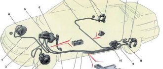
The following material will help to identify the causes of malfunctions of the VAZ 2110 stove:
Heater diagram VAZ 2110
We disassemble and repair the heater damper gearmotor of VAZ-2110, 2111 and 2112
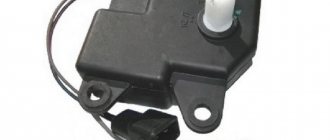
to disassemble and repair the heater damper gearmotor of VAZ 2110, 2111 and 2112 with our own hands . It is known that not all modifications of the stove are suitable for the gearmotors discussed in this article. The materials were tested on a VAZ-2112 produced in 2005 and a VAZ-21113 produced in 2004. In our case, the car is equipped with a stove with an air filter but without recirculation, without air conditioning, without an automatic mode for adjusting the temperature of the stove. So far, only two models of damper gearmotors have been examined in detail. The examples are quite vivid and will probably answer the question of which one to choose, what is more reliable than metal or plastic and is it better if it costs more... The first example is a heater gear motor 2110 in a plastic case , removed from the car for the first time in 10 years and installed on the car by the manufacturer. It stopped working for an unknown reason. Let's open it! View from different sides
First of all, we remove the plastic adapter of the gearmotor from the shaft, the one that is inserted into the damper itself and transmits rotation to it. We do this boldly, pull and remove, there is no glue or stoppers, the shaft has longitudinal milling that practically eliminates incorrect installation during assembly, but more on that later.
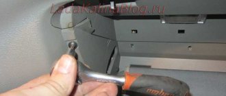
Along the perimeter of the product body we find several latches of this type
Here, to open it you will need a pair of flat screwdrivers, wider and narrower. It's better to take old ones because you'll have to sharpen them sharper. Oddly enough, there are no grooves under the latches, they cannot be recessed by pressing them, there is nowhere for them to press, so we drive a small screwdriver between the latch tongue and the second half of the product body directly into the place where the tongue is held, not deep, just slightly raise the eye and the main thing is not to tear it off, just a little, this will be enough. We insert the second wide screwdriver next to the latch in the place where the housing halves connect, insert it and open the halves a little with a turning movement, while taking out the small screwdriver. So along the entire perimeter.
Further, carefully, small parts may fall out, it is important not to lose them. Then one half is removed completely, pulled up from the axis and we get this picture.
Three gears, remove them safely
On the second there remains an electric motor with a gear on the shaft
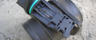
We pay attention to a few little things when removing the motor from the housing; at the end of the worm gear there is a segment designed for centering the shaft and preventing the pair of gears from disengaging. This is a separate small detail, it is important not to lose it. In the body there is a semicircular recess for this segment, i.e. Otherwise you won’t be able to insert it, just one side. We also pay attention to the locking screw in the motor housing to see if it is lost or unscrewed. The stopper prevents the motor itself from turning in the product body.
The motor is taken out, the gear and segment are removed from its shaft, there is no glue or stoppers. We see that the motor shaft also has a milling to transmit rotation to the gear.
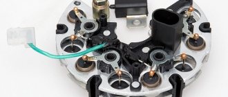
Having examined all the removed plastic gears, we conclude whether it is necessary to look deeper for the cause of the failure, if all the gears and their teeth are intact, the axles are in place, the stoppers, etc., then we probably need to look deeper. Let's disassemble the motor. From the side where the wires are connected, two places where the motor parts are fixed are visible; using something at hand, we bend the housing in these places, thereby freeing the bottom plastic part.
Then everything is interesting again, the insides are easy to break. There is a permanent magnet inside, it holds the armature of the motor inside with a magnetic field, so you can’t pull on the plastic bottom, in addition, there’s a big risk of tearing off the brushes and then everything will turn to dust. Here's how we do it. The motor has a rather long shaft, take the motor in your hand and press your finger on this shaft, pushing it in
You can see in the photo that the bottom part is hanging in the air, it is the brushes that hold it, and the anchor hangs on the magnetic field and tends to its place. It is still impossible to pull off the bottom part, we press the shaft as much as possible with our finger and with the other hand, we grab the anchor with our fingers, only using the anchor we separate the parts of the motor. You shouldn't take hold of the windings either, they are easy to damage, there is enough steel there, you shouldn't take hold of it. If your fingers do not fit, you can push the shaft with something thin, such as a nail or an awl, the anchor will come out stronger, and there will be more space.
Two brushes are attached to the bottom part; when disconnecting the armature and the bottom part, use a screwdriver to carefully pull the brush by its holder, one and then the other. No sudden movements. There is a washer at the end of the anchor, which prevents you from simply pulling the bottom part off the anchor; with this washer, the risk of tearing off the brushes is very high. This washer does not come off on its own and there is no point in trying, it is of no use.
We see three windings at the armature, inspect them, check with a tester on the commutator to see if these windings are intact. We inspect the bottom part, the brush holders, and the brushes themselves to see if there are any critical wear marks, melting, or soot. In this case, traces of soot and soot were found on the commutator, and in a certain position, because of this, there was no contact of the brush with the commutator.
Assembly. First the motor itself. Not forgetting about the washer on the anchor, moving one brush apart at a time, we insert the anchor into place. The bushing in the bottom part may turn sideways during disassembly, this is normal, it is self-centering, we place it in advance with the hole up so that the armature shaft fits into it during assembly. Here is the intermediate result, brushes on the washer...
We insert the shaft completely, make sure that everything went well, the brushes are intact and in place, touching the commutator.
Just like when disassembling, we take the anchor by the iron, insert it all into the case, don’t forget about the magnet, hold it tightly. When assembling, we clamp the hole for the long shaft with our finger so that the shaft does not slip under the influence of the magnet, release the finger and at the same time insert the bottom part until it stops. We check the ease of rotation of the shaft from the force of the fingers, bend the clamps of the bottom part. You can take a 9-volt battery of the Krona type and connect it to the terminals directly on the motor to check whether the motor is working. We take the half of the housing that has a socket for the connector, insert this connector into the housing, put the worm gear on the shaft, aligning the milling, everything is installed easily, without the use of force or something does not match. We put the segment on the gear, put it all in the housing, not forgetting about the locking screw, which must also be directed to the desired position. We tuck the wiring from the motor deep into the housing so that they do not interfere with further assembly. We place the shaft segment like this, in a semicircle up
The wiring is visible in its place
Time to put the gears in place. We start with the largest one, which has a shaft, and then take turns from there. The gear with the shaft does not have a full radius, it works from lock to lock, but it can be assembled in any position, just after assembly you will have to apply power and thus screw the shaft to the desired position so that it coincides with the square of the damper adapter.
We collected the gears and set them aside. We take the second cover; the damper position sensor remains installed on it. It must be removed before further assembly to avoid breaking it. On the inside we see three latches; by pressing, we do not force them out of the case too much, this way the sensor cover will be removed.
We remove the sensor from the socket and put it aside.
Aligning the hole with the shaft and the latches, we assemble both halves until the latches click, and assemble the body of the product
The sensor is a rotary type, the inner part rotates along with the shaft, the sensor does not have a stop, it rotates in a circle without restrictions, we are not afraid to break it, we turn the inner part until the slot coincides with the milling on the shaft, align the sensor into the socket and close the cover removed earlier.
And now all that remains is to put the adapter on the shaft, aligning the milling cutouts. The milling on the shaft on both sides is symmetrical, which means the adapter can be placed on the shaft in two positions. According to the manufacturer's idea, one corner at the upper end has a bevel; we direct this bevel towards the letters on the gearmotor housing.
In this gearbox, apart from plaque on the anchor, not a single part showed the slightest trace of wear on anything, the gears are like new, the teeth are perfect, but the product has not been standing for 10 years and the car has a mileage of more than one hundred thousand. There was a piece of paper stuck on the motor with the date
So we have restored the functionality of the damper gear motor for the stove of the VAZ-2110, 2111 and 2112. For this exclusive material, many thanks to Alexander, known under the nickname four-wheel drive
. Good luck to everyone on the roads and fewer breakdowns!
Replacement of micromotor gearbox
If it is necessary to replace the micromotor gearbox on a VAZ 2110, you need to carry out a number of simple operations. You will need to remove the frill, as well as the VUT and pedal assembly. Then dismantle the old heater gearmotor along with the plastic element and install a new micromotor gearbox instead of the damper sector, where there is exactly the same square. Replacing the gearbox usually takes place without any particular difficulties.
Before you start replacing the MMR, it is worth studying the design of the heating system, which is discussed in detail here:
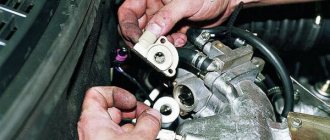
Installation of the micro-reducer damper is carried out with an assistant. You must first connect the contacts to the new motor. Turning the heater damper counterclockwise means supplying cold air, so you need to turn on the ignition and move the heater control system sensor to the position opposite the blue dot.
You can also do the opposite and check the micromotor-reducer, that is, turn the damper clockwise until it stops, and install the sensor opposite the red dot. The micromotor gearbox of the stove will rotate more than necessary, and for the installation to go smoothly, you can use a special lubricant for the square.
It is necessary to install the motor so that the holes for the screws coincide. Then the assistant turns the temperature regulator and at the same time presses the motor inward. The coincidence of the squares means that the replacement was successful and the gearbox should provide air flow at the desired temperature.
If the square does not go the entire length of the damper, it’s okay, the micromotor-reducer can only go a third, and this will not affect the functioning in any way. Then screw in the screws and turn the gearbox a few more times - from the blue mark to the red mark and in the opposite direction. This is done so that the stove system remembers the operating range and in the future the gearmotor works properly.
As a result, when you turn the heater damper of the gearmotor on a VAZ 2110, it immediately takes the required position, and in mode “A” the adjustment occurs automatically.
The subtleties and nuances of stove damper repair are presented in the following article:
Diagnostics, repair and replacement
You can check the gearmotor immediately after dismantling. You need to apply 12 volts to the contacts of the power connector. The easiest way is to take this voltage from the battery. We put two wires on the battery and connect them to the connector contacts. The gearmotor shaft should begin to rotate. When the polarity changes, the shaft movement must be reversed.
If this does not happen, disassemble the gear motor. If the servo drive operates, then the problem is in the control unit or wiring.
You can only disassemble the micromotor gearbox of a new type on your own. The plastic case is held on by clamps and can be easily separated into two halves with little effort.
After disassembly, we try to rotate the worm of the electric motor shaft with our fingers. If it rotates easily, then the mechanical part is working properly. Inspect the gear teeth. The recesses in the top cover for the gear shafts must be intact, without chips or ellipsoidal wear.
We try to apply voltage to the motor directly, past the chip. In some cases, a break is observed precisely in this area. If even after applying voltage directly nothing happens, the repair of the gear motor of the VAZ-2110 stove can be stopped at this point. The motor is faulty. It will be necessary to install a new motor or completely replace the gear motor, which is usually done due to the lack of suitable electric motors on sale.
Video: The stove on the VAZ 2110 does not heat up? Replacing the heater damper gearmotor
Replacing the gear motor of the VAZ 2110 stove of the new model, like the old one, is carried out in the reverse order of dismantling.
The only recommendation at the installation stage is to check the functionality of the new part. There are cases where even new spare parts had defects. And if you purchased a used servo drive, checking is required.
Installation of gear motor
In order to install the gearmotor on a VAZ 2110, you need the following tools: a Phillips screwdriver and a 10-open-end wrench. Replacing and installing a part such as a gearbox does not require special knowledge and skills; even a beginner can cope with such a task.
To gain access to a part such as a micromotor gearbox, you must first remove the windshield wipers from the fuse. To do this, unscrew the contact nut, and then release the frill and access to the screws will open. Unscrew the two nuts on the sides of the frill and remove the rubber seal from the electric motor compartment of the heater gearbox.
First, the pipeline of the heater damper frill on the VAZ 2110 is disconnected, then the screws holding the thermal radiators of the gearbox are unscrewed. The motor is located in the left compartment of the heater damper gearbox on the VAZ 2110, next to the brake booster. You need to unscrew the two bolts at the top.
Then the screw at the bottom is removed and the electric motor is dismantled. The damper is assembled in exactly the reverse order after the gearmotor is installed.
General information about the heater damper and gearmotor
Replacing a gearmotor in a VAZ 2110
As you know, a car interior heater is capable of filling the interior not only with warm, but also with cold air. The heater damper regulates the speed at which the desired temperature in the car interior is established.
Note. Before turning on the heater, all doors and windows of the car must be properly closed to create a high degree of internal tightness. Otherwise, the heater will be ineffective during its operation.
List of main functions of the heating damper gearmotor:
- maintaining optimal temperature conditions;
- The heater damper gear motor is also responsible for the speed of creating the proper temperature regime;
- determines the operating efficiency of the heater itself.
Objective reasons that directly indicate the presence of a malfunction of the heating damper and gear motor:
- the heater has stopped filling the car interior with cold or hot air;
- after 15-20 minutes of operation of the heater, no change in temperature is observed;
Replacement of gear motor VAZ 2110
- the rate at which the car interior is filled with appropriate air is too low and the practical effect of the heater’s operation is almost unnoticeable.
Note. The degree of sound insulation of a car interior is an objective indicator of the degree of insulation. Sometimes the problem of inefficient functioning of the heater lies precisely in the low degree of insulation.
Repair of the heater damper gearmotor 2110 new model
When the new type of gearmotor is removed, you should disassemble the housing, which is held in place by clamps, which should be carefully pryed off using a flat-head screwdriver.
First of all, inspect the motor for damage; to do this, connect it to the connector in the engine compartment.
The micromotor must be disassembled by bending the pressed side. Mark the position of the cover relative to the housing, which will help maintain the correct polarity of the electric motor during assembly.
If you find a fault in the motor, start looking for a break. If the part works, lubricate it and the gears on the gearbox. Silicone grease is ideal and can be used over a wide temperature range.
The throttle position sensor may need to be replaced, so you should pay attention to that too. The assembly is assembled in the reverse order.
Geared motor VAZ 2110, device, purpose and principle of operation
The opening/closing of the damper is performed by the heater damper gear motor using signals from the heater control system, as a result of which the air that enters the cabin is heated or cooled as needed. Note that the configuration of the “tens” gear motor may differ significantly depending on the year in which the car was produced. The gearmotor itself looks like a small electric motor. Often a broken device is completely replaced, since repairing it is quite problematic.
Removing the gear motor of the VAZ-2110 heater
To access the micromotor gearbox of the VAZ-2110 heater, regardless of the year of manufacture of the car, you will need to perform several simple operations.
- We remove the wipers. They are fastened with two nuts. Raise the protective caps and unscrew the fastening nuts with a 14 mm wrench.
- We dismantle the upper protection of the engine compartment - frill. To do this, unscrew the screws with a Phillips screwdriver, some of which are hidden under round plastic plugs.
- We remove the sound insulation of the engine shield. It is secured with screws. To dismantle it, you will need to disconnect the coolant supply pipes.
- We disconnect the trapezium of the wipers, which is attached to the body with two nuts.
The vacuum brake booster can be removed, but this operation is not necessary. But then, when unscrewing the screws of the gearmotor, you will need a short screwdriver or a ratchet with a screwdriver attachment.
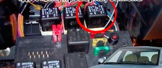
On the left side in the direction of travel of the car, near the partition of the engine shield above the vacuum booster, there is a micro-reducer for controlling the heater damper of the VAZ-2110. Two chips are connected to it. A more massive feature is nutrition. It supplies voltage to the windings of the electric motor. The smaller chip is a control chip, reads the position of the shaft and sends this information to the control unit. Let's disconnect these chips. The power supply may have a metal fixing bracket. Don't forget to lift it up with a flat screwdriver.
Modernization of the electric heating damper drive on the VAZ-2110
The decision to replace the heater damper drive with convenient automatic control appeared almost simultaneously with the release of the 2110 VAZ model. A variety of methods have been proposed and tested. But it has not yet been possible to choose the final result. As a result, the automatic heater damper on the VAZ-2110 is installed in various ways.
When making an electric drive for the stove damper, you should take into account the following nuances:
– what type of automatic control system is installed, since this affects the connection diagram; – decide which micromotor gearbox (MMR) is installed on the heater (if this MMR was produced before 2005, then it needs to be improved).
Options for upgrading the heater damper to automatic adjustment:
1. Use a standard gearmotor from a VAZ-2110 model car. 2. Use the stepper electric damper drive from the VAZ 2170 (Lada Priora).
The difference between these two options is that in the first you have to fix (delay) the position of the button until the damper is in the desired position. Only then release the button.
As for the second option, it is the most successful. Because setting the damper, based on the selected position, occurs automatically.
So, about these two options in more detail:
Improvement of the heater damper using a VAZ 2110 gear motor.
To do this, the following components are required:
– presence of a VAZ 2110 gearmotor; – if there is a desire to remake the gearmotor lever, then a VAZ 2110 micromotor gearbox, produced before 2003 (1,300 rubles); – presence of a button – to control the gear motor (50 rub.);
To set the damper location indicator, you will need a 12-position switch. Also, using this example, you can create a gearmotor control lever.
This gearmotor is located inside the panel itself.
The gear motor control should be placed on a separate button. To securely fix the button, you can use an old watch. As for the self-propelled gun, it needs to be moved from the central part to the sides.
LEDs can be used to make the location of the damper visible. Distribute the sector into 5 contact zones. Solder a separate wire to each contact, and the upper sliding contact located on these five contacts will go to the gear lever.
The result is an indication of five damper positions:
– two extreme positions – at the feet and directly on the face; – one middle position – on the glass itself.
Another option for the heater damper location indicator is as follows:
You can use a 12-position switch. In the central part, one common contact is installed (either “-” or “+”), and the other contacts are arranged in a circle, using the opposite current. And connect LEDs to them.
Replacing the old type gear motor with a new one. Dedicated to all owners of the C/O heater.
And so you found out that your Micro Motor Reducer (hereinafter referred to as MMR) has given up its life. The position of the damper does not correspond to the position of the SAUO set pointer or the MMR simply wedges and stops in any position other than the desired one, etc. and so on. Moreover, you are the happy owner of a 2110 Old Model heater (hereinafter referred to as S/O).
And so you come to the store and the seller offers you MMR S/O for a modest 1200-1500 rubles (while smiling slyly). I don’t know about you, but my toad was categorically against paying so much hard-earned money for an electric motor. At the same time, the MMR of the New Sample (hereinafter referred to as N/O) costs 450-600 rubles. Is this a normal difference? At the same time, the cunning salesman claims that they are not interchangeable. Now I’ll tell you how to save at least 500 rubles without much stress. And so you buy MMR N/O for 450-600 rubles and go to disassemble the heater. I think it is unnecessary to describe the removal of the frill and vacuum booster; this hemorrhoid is already familiar to all owners of the 10th family and Prior. I will say that the MMR is located behind the vacuum booster on the heater housing.
1. Unscrew the MMR S/O. 2.Then parts number 1 and 2.
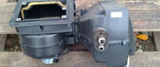
Behind part No. 2 we see the damper square (have you already guessed, no?). Yes, everything is correct MMR N/O is installed in place of part No. 2.
In turn, parts No. 1 and No. 2 are sent to the trash, following MMR S/O (so that he doesn’t get bored alone)). For ease of installation, first connect the power to the MMR and turn on the ignition. Ask someone to switch the temperature dial, while you insert the MMR by aligning the square with the damper. We screw the MMR, put on the second connector and check the functionality. There is no need to plug the hole from the old MMR with anything (it is not through). We assemble the frill and everything that we took apart))) Now you are the happy owner of a C/O heater with MMR N/O. Good luck to all.
Source
Repair of the micromotor of the stove gearbox of the new VAZ 2110-12 model
| In VAZ cars of the tenth family, the air flow (cold or hot) going into the cabin is controlled by a damper, which in turn is controlled by a micromotor-gearbox (MMR). It may be the cause of the stove’s malfunction, but do not rush to change it, try to repair it yourself. |
Depending on the year of production of the VAZ 2110, 2111 or 2112 (the turning point year 2003), the MMR can be old or new. Next we will talk about the new type of MMR.
System Features
VAZ 2110 heating system control
The heater control system has the following features:
- It is necessary to maintain a constant temperature in the car, which was specified by the driver.
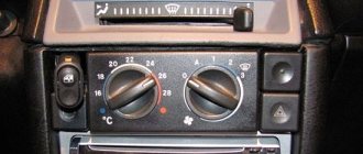
- As a control unit, there is a controller, which is equipped with two handles. Actually, with their help the management process takes place.
Note: the handles are divided into right and left. Using the left one, you can set the desired temperature in the cabin, and the right handle allows you to turn on the fan.
- The heater controller receives the necessary information about how the heater damper is located. The position of this damper is adjusted in accordance with the data set by the driver.
Controller for automatic heater control system VAZ 2110
- To ensure that the air in the car warms up as quickly as possible, a circulation valve is used, which has its own switch.
Note: if you turn on this valve, no outside air enters the cabin, so you need to be prepared for the fact that the car will become very hot.
- If you want to cool the air in the cabin, you can use the electric motor fan. If the heater motor is faulty, it is advisable to replace it.
Note: it is possible to repair it. However, in this case, only one option is considered - cleaning the collector.
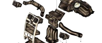
Stove components
Usually in winter there are problems with the operation of the stove. For some, it stops heating the air worse, for others, it does not heat at all. There are even cases when the air does not heat up, but cools down, because it is not working properly. Perhaps one of the elements of the heating system has been damaged. Let's look at what it consists of:
- Controller. It is also called the SAUO block. With its help, the required temperature is set. It also regulates the flow of cold or warm air to heat or cool the interior.
Automatic control system controller
Note: two types of controllers are suitable for the VAZ 2110 - four and five positions. They are quite difficult to find as they are no longer produced these days.
- Air temperature sensor. It shows what temperature is in the cabin. It has a small fan built into it.
Note: by the way, if the impeller of this fan stops spinning, then problems may occur. The solution can be simple: either replace the fan or clean it of dirt, if there is any.
- Micromotor gearbox. There are two types on sale: old and new samples. It’s better to take the first one, since the second one may not be suitable.
How to set up a controller
To increase the accuracy of temperature maintenance, you need to adjust the heater. For this:
- Remove the controller from its socket. This must be done as carefully as possible so as not to damage its parts.
- A trim potentiometer will help adjust the sensor.
- Its adjustment must be carried out in accordance with the calculation: one revolution of the potentiometer corresponds to 0.2 degrees.
Note: if you rotate clockwise, the temperature drops, and if you rotate it counterclockwise, the reverse process occurs.