05/08/2020 632 Generators
Author:Ivan
Depending on the device and operating principle, generator voltage relay regulators in a car are divided into several types: built-in, external, three-level and others. Theoretically, such a device can be made independently; the simplest and cheapest option in terms of implementation is to use a shunt device.
[Hide]
Purpose of the relay regulator
The generator voltage regulator relay is designed to stabilize the current in the installation. When the engine is operating, the voltage in the vehicle's electrical system must be at the same level. But since the crankshaft rotates at different speeds and the engine speed is not the same, the generator unit produces different voltages. Without adjusting this parameter, malfunctions in the functioning of the electrical equipment and devices of the machine may occur.
Interconnection of car current sources
Any car uses two power sources:
- Battery - required to start the power unit and primary excitation of the generator set. The battery consumes and stores energy when recharging.
- Generator. Designed for power and needed to generate energy regardless of speed. The device allows you to replenish the battery charge when operating at high speeds.
In any electrical network, both nodes must be working. If the DC generator fails, the battery will last no more than two hours. Without a battery, the power unit, which drives the rotor of the generator set, will not start.
The LR West channel talked about electrical faults in Land Rover cars, as well as the relationship between the battery and generators.
Voltage regulator tasks
Tasks performed by an electronic adjustable device:
- change in current value in the excitation winding;
- the ability to withstand a range of 13.5 to 14.5 volts in the electrical network, as well as at the battery terminals;
- turning off the power to the field winding when the power unit is turned off;
- battery charging function.
“People's Auto Channel” spoke in detail about the purpose, as well as the tasks performed by the voltage regulator device in a car.
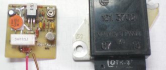
Voltage Regulator Upgrade
This is another option to improve the quality of the relay and its resistance to transient moments. The standard relay 50.3702-01 was taken as a basis, with only one resistor and capacitor added to the circuit.
In the diagram, the modification is indicated in red and, as you can see, does not require much effort or special experience in radio electronics. When the voltage in the on-board electrical network increases, capacitor C2 begins to charge. In this case, part of the current flows through the base of transistor VT1 and is proportional in magnitude to the rate of voltage increase. This leads to the opening of transistor VT1 and the closing of transistors VT2 and VT3. In this case, the current in the excitation coil decreases, and earlier than without an additional installed circuit. This allows you to significantly reduce voltage fluctuations in the network or eliminate them altogether. The same goes for reducing voltage. In other words, the permissible voltage limits are narrowed, and the smoothness of stabilization increases.
In this diagram, you can also introduce another rational proposal. As you know, the output voltage of the generator is optimized depending on the ambient temperature and in winter it should be higher by 0.8 V, reaching somewhere around 14.6 V. According to the standard, seasonal adjustment is performed by removing or installing jumpers S1, S2 and S3. Installing jumpers eliminates resistors R1, R2 and R3 from the circuit and the output voltage increases. When the jumpers are removed, the transistors turn on again and the voltage drops. To avoid this, the mentioned transistors can be replaced with one trimmer and the output voltage can be adjusted more easily and with greater accuracy.
A generator voltage regulator relay has been created to adjust the “voltage” supplied to the on-board network and to the battery terminals in a given range of 13.8 - 14.5 V (less often up to 14.8 V). In addition, the regulator adjusts the voltage on the self-excitation winding of the generator.
Types of relay regulators
There are several types of automotive relay regulators:
- external - this type of relay allows you to increase the maintainability of the generator unit;
- built-in - installed in the rectifier plate or brush assembly;
- changing in minus direction - equipped with an additional cable;
- regulated by plus - characterized by a more economical connection scheme;
- for installation in AC units - the voltage cannot be adjusted when applied to the excitation winding, since it is installed in the generator;
- for direct current devices - relay regulators have the function of cutting off the battery when the engine is not running;
- two-level relays - today they are practically not used; they are adjusted using springs and a lever;
- three-level - equipped with a comparison module circuit, as well as a matching signaling device;
- multi-level - equipped with 3-5 additional resistor elements, as well as a control system;
- transistor samples - not used on modern vehicles;
- relay devices - characterized by more improved feedback;
- relay-transistor - have a universal circuit;
- microprocessor relays - characterized by their small size, as well as the ability to smoothly change the lower or upper operating threshold;
- integral - installed in brush holders, so they change when they wear out.
DC relay regulators
In such units, the connection diagram looks more complex. If the car is stationary and the engine is not running, the generator unit must be disconnected from the battery.
When performing a relay test, you must ensure that you have three options:
- battery cut-off when the vehicle is parked;
- limitation of the maximum current parameter at the unit output;
- possibility of changing the voltage parameter for the winding.
AC relay regulators
Such devices are characterized by a more simplified testing scheme. The car owner needs to diagnose the voltage level on the excitation winding, as well as at the output of the unit.
If an alternating current generator is installed in the car, then it will not be possible to start the engine “from a pusher”, unlike a direct current unit.
Built-in and external relay regulators
The procedure for changing the voltage value is carried out by the device at a specific installation location. Accordingly, the built-in regulators influence the generator unit. And the external type of relay is not connected to it and can be connected to the ignition coil, then its work will only be aimed at changing the voltage in this area. Therefore, before performing diagnostics, the car owner must make sure that the part is connected correctly.
The “Sovering TVi” channel spoke in detail about the purpose and operating principle of this type of device.
Two-level
The operating principle of such devices is as follows:
- Current flows through the relay.
- As a result of the formation of a magnetic field, the lever is attracted.
- A spring with a specific force is used as a comparing element.
- When the voltage increases, the contact elements open.
- Less current is supplied to the field winding.
In VAZ cars, mechanical two-level devices were previously used for regulation. The main disadvantage was the rapid wear of structural components. Therefore, instead of mechanical ones, electronic regulators began to be installed on these machine models.
These parts were based on:
- voltage dividers, which were assembled from resistor elements;
- A zener diode was used as a reference part.
Due to the complex wiring diagram and ineffective voltage level control, this type of device has become less common.
Three-level
This type of regulators, like multi-level ones, are more advanced:
- The voltage is supplied from the generator device to a special circuit and passes through a divider.
- The received data is processed, the actual voltage level is compared with the minimum and maximum values.
- The mismatch pulse changes the current parameter that is supplied to the excitation winding.
Three-level devices with frequency modulation do not have resistance, but the frequency of operation of the electronic key in them is higher. Special logic circuits are used for control.
Control by minus and plus
The circuits for the negative and positive contacts differ only in connection:
- when installed in the positive gap, one brush is connected to ground, and the second goes to the relay terminal;
- if the relay is installed in the minus gap, then one brush element must be connected to the plus, and the second - directly to the relay.
But in the second case, another cable will appear. This is due to the fact that these relay modules belong to the class of active type devices. For its operation, a separate power supply is required, so the plus is connected individually.
Photo gallery “Types of generator voltage regulator relays”
This section presents photos of some types of devices.
Remote device type
Built-in regulator
Transistor-relay type
Integral device
Device for DC generator
AC control device
Two-level device type
Three-level control device
GU or generator
The generator in any automotive electrical circuit performs the dominant functions. The normal functioning and operation of the machine depends on it. Reliable PG is installed in all foreign cars and models of the domestic automobile industry.
VAZ car generator
For example, a GU is placed on the “six”, the charge of which satisfies the need for electricity of any standard component. If you do not overload the generating device of the “six”, then the car is capable of driving many, many more kilometers. However, it is important to carry out preventive procedures in a timely manner - monitor the belt tension and the condition of the brushes.
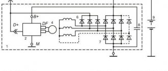
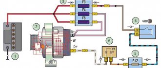
The GU is connected according to the classical scheme. Using the VAZ 2106 generator as an example, let’s consider its functioning. This GU is marked as G-221. It is an AC synchronous electric machine with ELMG excitation. A VB (rectifier) with 6 diodes is built inside the GU.
Connection diagram for a generator on a VAZ
| 1 | generator rotor winding |
| 2 | generator |
| 3 | generator stator winding |
| 4 | generator rectifier |
| 5 | accumulator battery |
| 6 | ignition switch |
| 7 | battery charge indicator lamp |
| 8 | battery warning light relay |
| 9 | fuse box VAZ -2106 |
| 10 | throttle |
| 11 | temperature compensation resistor |
| 12 | additional resistors |
| 13 | voltage regulator |
A simple and understandable scheme that does not require any subtleties or specific knowledge. On the “six” the PG is located on the engine on the right. It is attached to the tension bar with a nut and to the bracket with its claws.
As you can see, the diagram shows an external regulator. It is marked with the number 13. The generator is indicated with the number 2, the fuse box is indicated with the number 9.
Separately, I would like to consider the relay, which plays an important role in the “six” generator circuit. First of all, it serves to provide information to the driver about the charging status. As is known, it is created by a generating device.
The relay is made on the same principle as all devices that function according to the same properties. The connection is made to terminal 30 of the generator. A separate wire goes through the fuses to the 3Z (lock).
The action of the relay boils down to the following: as soon as the voltage of the BS decreases (falls below the 12-volt value), the relay contacts open, the indicator is activated, giving a sign to the driver.
To better understand the connection diagram, it is recommended that you also familiarize yourself with the principles of battery charging:
- as soon as the key is turned into the 3Z, an electric pulse is supplied to the relay regulator through the fuse (pin 15);
- in the regulator the voltage is transformed and goes further to the positive brush of the GU;
- then, through the brush, the voltage goes to the excitation winding of the GU;
- then - to the negative brush, through which it is brought to ground.
After the relay is activated or after the normal voltage value has been reached in the BS, the GU begins to generate current with the required value. The indicator lamp goes out, and the circuit starts working in factory mode. But when the total voltage drops, the current is not enough, and the contacts open, which leads to the discharge lamp burning.
Charge relay or warning lamp relay
The constant switching on of the charge indicator lamp indicates that the gene is not working properly. This happens for various reasons. First, you should check the fuses: if they are active, then both relays deserve attention: the regulator and the charger. If they are also in order, then faults must be looked for in the generating device itself.
Before proceeding with replacing the relay, it is recommended to carefully check the functioning of the regulator. The car starts, the speed is kept within the range of 2500-3000 rpm. After this, you need to turn off all current consumers, except the ignition. Then you need to measure the voltage at the battery terminals.
Operating principle of the relay regulator
The presence of a built-in resistor device, as well as special circuits, makes it possible for the regulator to compare the voltage parameter produced by the generator. If the value is too high, the controller is switched off. This allows you to prevent overcharging of the battery and failure of electrical equipment that is powered from the network. Problems with the device will damage the battery.
Switch winter and summer
The generating device operates stably regardless of the ambient temperature and season. When its pulley is set in motion, current is generated. But in the cold season, the internal structural elements of the battery may freeze. Therefore, the battery charge is restored worse than in the heat.
The switch for changing the operating season is located on the relay body. Some models are equipped with special connectors; you need to find them and connect the wires in accordance with the diagram and symbols marked on them. The switch itself is a device thanks to which the voltage level at the battery terminals can be increased to 15 volts.
VAZ 2101 generator bearings. Replacement
Sometimes the VAZ generator itself is in good working order and performs its direct function - providing the car with power and charging the battery. And when the bearings fail, there is no need to buy a new generator. You can simply replace the bearings.
Procedure for replacing generator bearings:
- To get to the bearing, as before, you need to disconnect the brush holder, and then unscrew the nut securing the generator pulley.
Unscrew the nut securing the VAZ generator pulley - Using a puller, you must press the pulley off the rotor shaft, then remove the pulley key and remove the back cover along with the stator.
We disassemble the stator and rotor - Next, remove the rotor assembly with the rear bearing from the front cover.
- Unscrew the nuts securing the front bearing caps, filing the ends of the screws.
Unscrew the nuts securing the front bearing cover of the VAZ generator - Then remove the screws, front bearing caps and press it out using a mandrel.
- To press out the rear bearing on the shaft, you need a two-fingered shaft bearing puller with narrow jaws, otherwise they simply won’t fit.
- The bearing is pressed out of the cover using a 27 head.
- Before knocking the rotor out of the bearing, you need to generously lubricate everything with a “vdshkoy”. Do not hit the nut on the shaft or the bare shaft with a hammer, otherwise the thread will be damaged. It is advisable to knock through some kind of spacer, for example a piece of wood.
- The bearing must be pressed into the cover along the outer race, and onto the shaft along the inner race, since the bearing is closed with two strips with rivets that need to be cut off.
Press the bearing into the generator cover - To assemble, you need to take new bolts and nuts, tighten them, and then begin assembly.
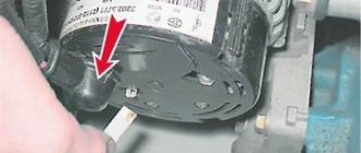
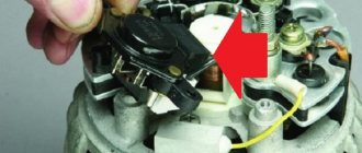
How to remove the relay regulator?
Removing the relay is allowed only after disconnecting the terminals from the battery.
To dismantle the device yourself, you will need a screwdriver with a Phillips or flat head. It all depends on the bolt that secures the regulator. The generator unit and the drive belt do not need to be dismantled. The cable is disconnected from the regulator and the bolt that secures it is unscrewed.
User Viktor Nikolaevich spoke in detail about the dismantling of the regulatory mechanism and its subsequent replacement with a car.
Alternator belt VAZ 2101
Quite often the belt on a generator breaks or becomes deformed (stretched), so it is very important to know how you can replace it yourself in any situation, even an emergency.
Replacing the VAZ 2101 alternator belt
The procedure for replacing a belt is almost the same as when replacing the generator itself. But there is no need to remove the generator itself.
Belt replacement procedure:
- The first step is to remove the battery, then slightly unscrew the nut that secures the generator to the adjustment bar, but you only need to loosen it, not unscrew it!
- Next, move the generator all the way to the engine, remove the old belt and start putting on the new one.
- First, we put it on the crankshaft and the generator pulley, then we put it a little on the pump pulley, and push it until it is completely dressed.
- Now you need to tighten it, lowering the generator in the opposite direction from the engine. With the required tension, the deflection should not exceed 10 mm .
- Tighten the nut.
- We install the battery.
Alternator belt size VAZ 2101
There are two types of belts for classics (width*thickness*length):
- 10*8*944
- 10*80*938
Symptoms of a problem
“Symptoms” that will require the control device to be checked or repaired:
- when the ignition is activated, a low battery indicator light appears on the control panel;
- the icon on the dashboard does not disappear after starting the engine;
- the brightness of the optics may be too low and increase with increasing crankshaft speed and pressing the gas pedal;
- the power unit of the car is difficult to start the first time;
- The car battery is often discharged;
- when the engine speed increases to more than two thousand per minute, the lights on the control panel turn off automatically;
- the dynamic properties of the vehicle are reduced, which is especially evident at increased crankshaft speeds;
- The battery may boil.
Possible causes of malfunctions and consequences
The need to repair the generator voltage regulator relay will arise when the following problems occur:
- interturn closure of the winding device;
- short circuit in the electrical circuit;
- breakdown of the rectifier element as a result of diode breakdown;
- errors made when connecting the generating set to the battery terminals, reversal;
- water or other liquid entering the body of the control device, for example, in high humidity on the street or when washing a car;
- mechanical failures of the device;
- natural wear and tear of structural elements, in particular brushes;
- low quality of the device used.
As a result of a malfunction, the consequences can be serious:
- High voltage in the vehicle's electrical network will lead to electrical equipment failure. The microprocessor control unit of the machine may fail. Therefore, it is not allowed to disconnect the battery terminals while the power unit is running.
- Overheating of the winding device as a result of an internal short circuit. Repairs will be expensive.
- Failure of the brush mechanism will cause the generator set to malfunction. The unit may jam and the drive belt may break.
User Snickerson talked about diagnosing the regulatory mechanism, as well as the reasons for its failure on cars.
Scheme and principle of operation
The operation of the stabilizer for all models is almost the same and consists in distributing the current supplied from the generator to stabilize it and further distribute it to consumers.
The operation of the stabilizer is almost the same for all models
The main peripheral consumers of the scooter include:
- battery;
- indicators;
- light bulbs;
- sensors;
- enrichment agent;
- other nodes;
- starting enrichment.
How does the stabilizer work? The main principle of its operation is to act as a transformer, which lowers the voltage to an optimal level acceptable for the operation of electrical appliances, and also stabilizes the network and prevents unexpected power surges.
If the relay malfunctions, the scooter’s devices fail, quickly wear out or burn out.
To avoid these problems and their undesirable consequences, you should know the basics of the correct operation of the electrical circuit and voltage components of the scooter (Figure 1).
Voltage relay pinout diagram and wiring for main scooter models
The pinout of the relay regulator is standard for all models of Chinese-made scooters.
Scooter relay-regulator pinout
The stabilizer has an aluminum body and plastic contacts, each of which has its own wire. Each contact has its own wire color. This makes it convenient to connect the device to the wires if the plastic connector is worn out. The wires must be connected to the contacts according to the electrical diagram (Figure 3).
Electrical diagram for connecting the relay regulator
Diagnostics of the relay regulator
It is necessary to check the operation of the regulatory device using a tester - a multimeter. It must first be configured in voltmeter mode.
Built-in
This mechanism is usually built into the brush assembly of the generator unit, so level diagnostics of the device will be required.
The check is done like this:
- The protective cover is dismantled. Using a screwdriver or wrench, the brush assembly is loosened; it must be brought out.
- The wear of the brush elements is checked. If their length is less than 5 mm, then replacement is necessary.
- Checking the generator device using a multimeter is performed together with the battery.
- The negative cable from the current source is connected to the corresponding plate of the control device.
- The positive contact from the charging equipment or battery is connected to the same output on the relay connector.
- Then the multimeter is set to the operating range from 0 to 20 volts. The probes of the device are connected to the brushes.
In the operating range of 12.8 to 14.5 volts, there should be voltage between the brush elements. If the parameter increases by more than 14.5 V, then the tester needle should drop to zero.
When diagnosing the built-in generator voltage relay-regulator, it is permissible to use a test light. The lighting source must turn on at a certain voltage interval and go out if this parameter increases above the required value.
The cable that controls the tachometer must be tested using a tester. On diesel cars this conductor is designated W. The resistance level of the wire should be approximately 10 ohms. If this parameter drops, this indicates that the conductor is broken and requires replacement.
Remote
The diagnostic method for this type of device is carried out similarly. The only difference is that the relay regulator does not need to be removed and removed from the generator unit housing. You can diagnose the device with the power unit running, changing the crankshaft speed from low to medium to high. When their number increases, it is necessary to activate the optics, in particular, the high beams, as well as the radio, stove and other consumers.
The AvtotechLife channel talked about self-diagnosis of the regulatory device, as well as the features of performing this task.
GU or generator
The generator in any automotive electrical circuit performs the dominant functions. The normal functioning and operation of the machine depends on it. Reliable PG is installed in all foreign cars and models of the domestic automobile industry.
For example, a GU is placed on the “six”, the charge of which satisfies the need for electricity of any standard component. If you do not overload the generating device of the “six”, then the car is capable of driving many, many more kilometers. However, it is important to carry out preventive procedures in a timely manner - monitor the belt tension and the condition of the brushes.
The GU is connected according to the classical scheme. Using the VAZ 2106 generator as an example, let’s consider its functioning. This GU is marked as G-221. It is an AC synchronous electric machine with ELMG excitation. A VB (rectifier) with 6 diodes is built inside the GU.
| 1 | generator rotor winding |
| 2 | generator |
| 3 | generator stator winding |
| 4 | generator rectifier |
| 5 | accumulator battery |
| 6 | ignition switch |
| 7 | battery charge indicator lamp |
| 8 | battery warning light relay |
| 9 | fuse box VAZ -2106 |
| 10 | throttle |
| 11 | temperature compensation resistor |
| 12 | additional resistors |
| 13 | voltage regulator |
A simple and understandable scheme that does not require any subtleties or specific knowledge. On the “six” the PG is located on the engine on the right. It is attached to the tension bar with a nut and to the bracket with its claws.
As you can see, the diagram shows an external regulator. It is marked with the number 13. The generator is indicated with the number 2, the fuse box is indicated with the number 9.
Separately, I would like to consider the relay, which plays an important role in the “six” generator circuit. First of all, it serves to provide information to the driver about the charging status. As is known, it is created by a generating device.
The relay is made on the same principle as all devices that function according to the same properties. The connection is made to terminal 30 of the generator. A separate wire goes through the fuses to the 3Z (lock).
The action of the relay boils down to the following: as soon as the voltage of the BS decreases (falls below the 12-volt value), the relay contacts open, the indicator is activated, giving a sign to the driver.
To better understand the connection diagram, it is recommended that you also familiarize yourself with the principles of battery charging:
- as soon as the key is turned into the 3Z, an electric pulse is supplied to the relay regulator through the fuse (pin 15);
- in the regulator the voltage is transformed and goes further to the positive brush of the GU;
- then, through the brush, the voltage goes to the excitation winding of the GU;
- then - to the negative brush, through which it is brought to ground.
After the relay is activated or after the normal voltage value has been reached in the BS, the GU begins to generate current with the required value. The indicator lamp goes out, and the circuit starts working in factory mode. But when the total voltage drops, the current is not enough, and the contacts open, which leads to the discharge lamp burning.
The constant switching on of the charge indicator lamp indicates that the gene is not working properly. This happens for various reasons. First, you should check the fuses: if they are active, then both relays deserve attention: the regulator and the charger. If they are also in order, then faults must be looked for in the generating device itself.
Before proceeding with replacing the relay, it is recommended to carefully check the functioning of the regulator. The car starts, the speed is kept within the range of 2500-3000 rpm. After this, you need to turn off all current consumers, except the ignition. Then you need to measure the voltage at the battery terminals.
Charging may disappear in the following cases:
- If the generator brushes are worn out.
- In case of malfunction of the generating device.
- If the charging relay is faulty.
- If the rectifier unit (diode bridge) fails.
Thus, installing an external relay-regulator instead of a built-in one will bring a lot of benefits. The fact is that modern charging systems have much more power. Thus, modern memory systems are much more complex than old-style systems.
Forget about fines from cameras! An absolutely legal new product - Traffic Police Camera Jammer, hides your license plates from the cameras that are installed in all cities. More details at the link.
- Absolutely legal (Article 12.2);
- Hides from photo and video recording;
- Suitable for all cars;
- Works through the cigarette lighter connector;
- Does not cause interference to radios and cell phones.
On the “classic” you can find 2 types of voltage regulator relays: built into the generator and external. The difference lies in the model of the generator that is installed on the car.
On older Zhiguli models (VAZ 2101, 2102, 2103, 2106, 2121 with carburetor engines) a G-221 generator is installed, and the external voltage regulator is a small “box”, which is secured with two nuts on the left mudguard of the body. It is precisely the replacement of such a regulator that will be discussed in this article.
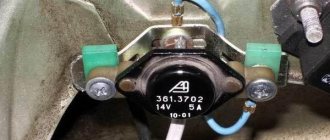
On later VAZ models (2104, 2105 and 2107) there is a G-222 generator, and the voltage regulator is already built into the generator housing and is a small black “tablet”.
Independent connection of the relay regulator to the generator’s on-board network (step-by-step instructions)
When installing a new control device, the following points must be taken into account:
- Before performing the task, it is necessary to diagnose the integrity and reliability of the contacts. This is a cable that runs from the vehicle body to the generator set housing.
- Then connect terminal B of the regulatory element to the positive contact of the generating set.
- It is not recommended to use twisted wires when making connections. They overheat and become unusable after a year of use. Soldering should be used.
- It is recommended to replace the standard conductor with a wire whose cross-section is at least 6 mm2. Especially if, instead of the factory generator, a new one is installed, which is designed to operate under current conditions above 60 A.
- The presence of an ammeter in the generator-battery circuit allows you to determine the power of power sources at a specific time.
Remote controller connection diagram
Connection diagram for remote type devices
This device is installed after the wire into which it will be connected is determined:
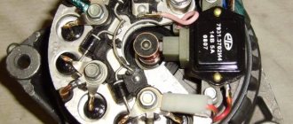
- In older versions of Gazelles and RAF, mechanisms 13.3702 are used. They are made in a metal or polymer case and are equipped with two contact elements and brushes. It is recommended to connect them to the negative open circuit; the outputs are usually marked. The positive contact is taken from the ignition coil. And the output of the relay is connected to the free contact on the brushes.
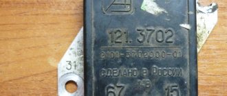
- VAZ cars use devices 121.3702 in a black or white case; there are also double modifications. In the latter, if one of the parts breaks down, the second regulator will remain working, but you need to switch to it. The device is installed in the open circuit of the positive circuit with terminal 15 to the contact of the B-VK coil. The conductor number 67 is connected to the brushes.
In newer versions of the VAZ, the relays are installed in the brush mechanism and connected to the ignition switch. If the car owner replaces the standard unit with an AC unit, then the connection must be made taking into account the nuances.
More details about them:
- The need to fix the unit to the vehicle body is determined by the car owner independently.
- Instead of a positive output, contact B or B+ is used here. It must be connected to the car's electrical network via an ammeter.
- Remote type devices are usually not used in such cars, and built-in regulators are already integrated into the brush mechanism. There is one cable coming from it, designated D or D+. It must connect to the ignition switch.
In cars with diesel engines, the generator unit can be equipped with output W - it is connected to the tachometer. This contact can be ignored if the unit is installed on a gasoline modification of the car.
User Nikolay Purtov spoke in detail about installing and connecting remote devices to a car.
Checking the connection
The engine must start. And the voltage level in the car’s electrical network will be controlled depending on the number of revolutions.
Perhaps, after installing and connecting a new generator device, the car owner will encounter difficulties:
- when the power unit is activated, the generator unit starts, the voltage value is measured at any speed;
- and after the ignition is turned off, the vehicle engine runs and does not turn off.
The problem can be solved by disconnecting the excitation cable, only then will the engine stop.
The engine may stall when the clutch is released and the brake pedal is pressed. The cause of the malfunction is residual magnetization, as well as constant self-excitation of the unit winding.
To avoid this problem in the future, you can add a light source to the gap in the exciting cable:
- the light will light when the generator is turned off;
- when the unit starts, the indicator goes out;
- the amount of current that passes through the light source will not be sufficient to excite the winding.
The Altevaa TV channel talked about checking the connection of the regulatory device after connecting the motorcycle to a 6-volt network.
Connecting the unit
Before discarding the device, you should make sure that other parts are in good condition. The belt, alternator, battery, and wires are subject to inspection. The lack of charging of the VAZ 2106 may be caused by a loose belt. If the unit was removed before checking, you should make sure that the wires are connected correctly.
Replacing the voltage regulator is done in a garage. Even an inexperienced driver can do this. You will need a tool, skillful hands and a little knowledge.
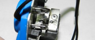
Open the hood to find the remote relay. In the Zhiguli, the box is attached with lugs to the left wing. We find the object near the brake fluid reservoir. Some relays are built into the generator housing. People call them integrals.
Do not rush to remove the wiring from the terminals. Experienced car enthusiasts are advised to first mark the wires with a marker. There are 2 gray and orange wires suitable for the VAZ voltage regulator. They are attached to terminals numbered 67 and 15. Do not mix up the wires. The gray color corresponds to the number 67, and the orange color corresponds to 15.
At the end, a re-check is carried out. Diagnosing and replacing the voltage regulator does not require much effort. It is not necessary to go to a service station. Save yourself the expense of material costs and repair the car yourself.
Schematic electrical diagrams, connecting devices and pinouts of connectors
The generator in cars is designed to generate electricity and charge the battery. If the normal operation of a car electric generator is disrupted, the battery begins to discharge and soon the car will stop starting completely - there is not enough battery charge. This device consists of a three-phase diode bridge, which, in turn, has 6 silicon diodes. Electrical voltage is created by the excitation of the rectifier at the moment when the rotor poles change under the stator windings. When the rotor rotates inside the machine stator, the poles of the rotor change. To increase the value of magnetic fluxes, the stator contains an electromagnetic exciting winding in the area of the magnetic cores. Marking and designation of wires:
- P - pink.
- F - purple.
- O - orange.
- B&W - black and white.
- KB - brown and white.
- CHG - black and blue.
- K - brown.
- H - black.
- B - white.
Tips for increasing the service life of the relay regulator
To prevent rapid failure of the regulatory device, you must adhere to several rules:
- Do not allow the generator set to become heavily contaminated. From time to time you should perform a visual diagnosis of the device's condition. In case of serious contamination, the unit is removed and cleaned.
- The tension of the drive belt should be checked periodically. If necessary, it is stretched.
- It is recommended to monitor the condition of the generator set windings. They should not be allowed to darken.
- It is necessary to check the quality of contact on the control cable of the regulatory mechanism. Oxidation is not allowed. When they appear, the conductor is cleaned.
- Periodically, you should diagnose the voltage level in the electrical network of the car with the engine running and switched off.
Is it possible to make a regulator with your own hands?
An example is considered on the regulatory mechanism for a scooter. The main nuance is that for correct operation the generator unit will need to be disassembled. A separate conductor must lead out the ground cable. The device is assembled according to the circuit of a single-phase generator.
Algorithm of actions:
- The generating set is disassembled and the stator element is removed from the scooter motor.
- There is ground around the windings on the left; it needs to be desoldered.
- Instead, a separate cable for winding is soldered. Then this contact is brought out. This conductor will be one end of the winding.
- The generator device is being reassembled. These manipulations are carried out so that two cables come out of the unit. They will be used.
- Then a shunt device is connected to the resulting contacts. At the final stage, the yellow cable from the old relay is connected to the positive terminal of the battery.