With a standard signal, not only is it a shame to honk, but you also have time to change it every spring. I installed signals from a new model “sable” in 2010, because... do not require modifications. I traveled with them for exactly 1.5 years. Closer to the age of 12, I began to notice that at a speed of 90 km, with the heater turned on in the middle position, the signal could not be heard at all, it definitely shouldn’t be like that! It's time to do something about it!
In the factory wiring of the sound signal, 12 Volts are constantly present at one of the terminals. Despite good insulation, it quickly oxidizes and turns green. Having removed the radiator grille, I also found one dead high-pitched signal... I couldn’t find the same signals from the “sable” with 2 contacts as there were. But in the accessories department of one of the auto stores I saw what I was looking for, the only thing that alerted me was the red color instead of black, and the signature VAZ 2107))) I decided to try it, and for good reason! I'll say looking ahead.
The absence of a sound signal on a car is a malfunction that affects traffic safety. The ability to promptly warn or attract the attention of pedestrians, as well as other road users, directly with the horn, can help avoid creating an emergency situation or an accident.
A malfunction such as the absence of a sound signal on VAZ family cars is quite easy to diagnose and repair with your own hands. To do this, you need to study the connection diagram (it is very simple) and follow the instructions to carry out the necessary checks.
Sound signal VAZ 2107
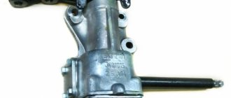
The manufacturer of the VAZ 2107 equipped the car with two versions of the sound signal (S). In the first case, two sound elements (SE) of low and high tonality were installed (signal types S-304 and S-305), which made it possible to obtain a loud and surround sound. These elements were mounted on a metal bracket in the engine compartment near the radiator of the cooling system.
The sound signal of the VAZ 2107 consists of two elements of different tones - S-304 and S-305
The second option involved installing one ZE type 20.3721–01, also located on a bracket in front of the cooling radiator. All sound elements are non-separable and cannot be repaired.
The sound signal of the VAZ 2107 consists of one element 20.3721–01
Purpose of the sound signal
The sound signal is designed to warn road users of danger and prevent accidents. The signal is given by pressing the ZS button, which is located on the steering wheel.
Traffic rules limit the use of ES to two situations.
Traffic rules Chapter 19.10. Sound signals can only be used:
– to warn other drivers about the intention to overtake outside populated areas;
– in cases where it is necessary to prevent a traffic accident.
Traffic rules of the Russian Federation
https://www.pdd24.com/
In the first case, the vehicle informs the driver of the car being led before the start of the maneuver. The situations that fall under the second paragraph of the traffic rules are more varied. The following options are possible.
- During icy conditions, a person is walking along a pedestrian crossing, and the slippery road does not allow you to brake sharply. Having heard the signal, the pedestrian will react.
- The driver moving in the next lane did not see you in the side mirror and began to change lanes. By giving a signal, you will draw his attention to you.
- An animal came out onto the roadway. You can use a sound signal to drive him off the road.
- When leaving a secondary road, the driver did not see your car moving along the main road. ZS will force him to stop his car.
- The cyclist moves not along the edge, but in the middle of the roadway. The sound of the signal will make him let the car pass.
There are many such cases. Timely and reasonable use of traffic signals will allow road users to avoid big troubles.
Sound signal device VAZ 2107
The housing of the electronic device contains a metal membrane, which oscillates due to the movements of the metal armature. These vibrations are the source of sound. The armature itself is driven by a magnetic field created by a coil and winding.
The VAZ 2107 sound signal is designed quite simply: 1 - yoke; 2—ZE building; 3 - winding; 4 - core; 5 - anchor; 6 — adjusting screw; 7 - bridge; 8 — textolite plate; 9 — fixed contact holder; 10 — movable contact plate; 11 - membrane; 12 — diffuser; 13 - ring
The principle of operation of the ZS VAZ 2107 is as follows. The electromagnetic field that occurs when voltage is applied to the coil pushes out the membrane armature, which, in turn, opens the breaker and turns off the coil. As a result, the membrane returns to its original position, and the armature again closes the breaker contacts. As a result of repetition of such cycles, the membrane vibrates, producing sound.
Electrical diagram for connecting the sound signal of VAZ 2107
The connection diagram for a VAZ 2107 sound signal with two elements of different tones is quite simple.
VAZ 2107 sound signal connection diagram: 1 - sound signals; 2 - relay and fuse block; 3 — signal activation button on the steering wheel; РЗ — sound signal relay; A - generator plus
The principle of operation of the VAZ 2107 sound signal
Voltage is supplied to the terminals of the sound elements through a relay designed to close and open an electrical circuit with a high load. This low current controlled relay avoids overloading some controls. Its malfunction can lead to overheating of control buttons and toggle switches and their failure.
When the contacts of the signal activation button are closed, terminal 85 of the relay is connected to ground (the negative terminal of the battery). In this case, positive is constantly supplied from the generator to terminals 86 and 30 of the ZS relay. Terminals 85 and 86 are the negative and positive of the relay coil. When voltage is applied to them, the contact between terminals 30 and 87 is closed. A plus is supplied to the last terminal, which is connected to the positive contact, through the normally open contact. As a result, when the negative contact of the protective element is constantly connected to ground, an audible signal is triggered.
Modifications
Switching diagram for electric windows of the front doors
1 - main fuse block; 2 — relay for turning on electric windows; 3 — left door power window switch; 4 — right door power window switch; 5 — gear motor for the right door electric window; 6 — gear motor for electric window lifter of the left door; 7 - additional fuse block; 8 — ignition switch; A - to terminal “30” of the generator; B - to the instrument lighting switch; B - conventional numbering of plugs in the gear motor block.
Carburetor solenoid valve control circuit
1 - ignition switch; 2 - generator; 3 - battery; 4 — ignition coil; 5 - switch; 6 — control unit; 7 — carburetor solenoid valve; 8 — carburetor limit switch.
Engine cooling fan motor
1 - generator; 2 - battery; 3 — ignition switch; 4 - main fuse block; 5 — electric fan activation relay, 6 — electric fan activation sensor; 7 — electric fan; 8 - additional fuse block
Installing an additional button on the VAZ 2107 sound signal
The moving contact between the steering wheel and the steering column of the VAZ 2107 fails over time. His foot loses elasticity and the contact parts no longer touch. To prevent such a situation, car owners often install an additional button to sound a sound signal, duplicating the functions of the button on the steering wheel, that is, connecting the relay to ground. It is installed in any convenient place, most often on the instrument panel near the steering wheel.
Often VAZ 2107 owners install an additional button to sound the sound signal.
An additional button is installed as follows.
- We make a hole of a suitable diameter on the instrument panel.
- We install the button in the hole made.
- If the button is three-contact, we determine which contacts close when it is pressed. This can be done using a multimeter.
- In the common wiring harness, we find the wire going to the ZS button on the steering wheel. This is usually a gray wire with a black stripe.
- We connect this or a wire parallel to it to one of the contacts of the button.
- We connect the second terminal of the button to ground.
A button connected in this way will repeat the functions of a button on the steering wheel.
Personal experience shows that using the signal button installed on the instrument panel is inconvenient. You won’t be able to get used to it enough to promptly sound a beep without looking at it. As a result, precious fractions of a second are lost when they could be vital. It's worth spending the money and taking a little time to fix your steering wheel signal.
Mounting block malfunctions and repairs
If a malfunction is detected in the electrical system of a car, first of all you need to pay attention to the mounting block - most often the breakdown is associated with the failure of its individual components. There are four main possible malfunctions of the mounting block:
IMPORTANT. The most common cause of a malfunction is a blown fuse. Before changing a fuse, you should find out the reasons for its blown; this is often due to a breakdown of the protected component or a short circuit in the circuit protected by this fuse.
A relay malfunction is diagnosed quite simply: first you need to try to change the fuse. If this does not help, a jumper wire should be inserted between the relay contacts; if after this a current appears in the circuit (that is, the malfunction is eliminated), then the relay must be replaced. In another case, the cause of the breakdown must be sought in the circuit itself. In modern mounting blocks, relays are installed using solderless connectors, so repairs can be carried out fairly quickly.
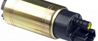
Installation of a pneumatic sound signal on a VAZ 2107
Some car owners install a powerful pneumatic sound signal on the VAZ 2107. Installation of such a device is quite simple. You will need a grinder, a drill and a standard set of plumbing tools.
Universal pneumatic horn model fits most cars
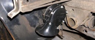
First you need to determine where the horn and compressor will be located, and then make brackets to mount them. Typically, the pneumatic signal is installed behind a decorative grille in front of the radiator.
The pneumatic signal is usually placed in front of the cooling radiator
Installation is carried out in the following order:
- We make brackets from a suitable material (metal corner or strip).
- We install the brackets on the top panel in front of the cooling radiator in accordance with the dimensions of the pneumatic claxon and the design of its fastenings.
The manufactured brackets are screwed into places suitable for attaching the pneumoklaxon - We install the pneumoklaxon on the brackets.
- We mount the compressor on the standard signal brackets or on the panel near the radiator.
The air compressor is installed next to the cooling radiator - We connect the horn and the compressor with a hose from the pneumatic signal kit.
- We connect power to the pneumoklaxon from the standard AP.
If the current consumed by the compressor is more than 5 A, according to the scheme described above, you will need to install an additional relay to be on the safe side.
A pneumatic horn is impractical because it is equipped with a compressor that has a delay in starting. The compressor is short-lived and may quickly require replacement; moreover, in severe frosts, the compressor may fail and the signal will not sound.
In practice, the installation algorithm for a pneumoklaxon is determined by its size, type, design of fastenings, etc.
Checking the electrical circuit
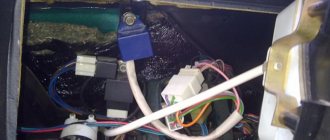
Problems occur when the electrical circuit of the audio signal is disconnected. To find the cause, you need to check the entire electrical circuit: wires, connectors. The figure shows the electrical circuit of the horn from the mounting module to the steering wheel, where the signal button is located.
The electrical diagram is also available in the vehicle registration certificate. Oxidation or weakening of contacts leads to disruption of the electrical conductivity of the connectors. Therefore the signal does not turn on. Failure of insulation in wires causes short circuits and blown fuses. It is necessary to check the electrical circuit, all its connectors with a multimeter and troubleshoot:
- Find out the reason for the blown fuse and eliminate it.
- Clean oxidized contacts.
- If necessary, connectors and wires should be replaced.
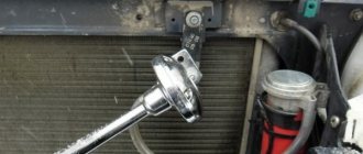
The picture shows how the horn contacts are checked.
Important : you can work with the battery connected, but with the ignition off. Don't neglect safety measures.
Helpful information
Due to the unification of many electronic components of the VAZ family, car enthusiasts waste time searching for the required wiring, not suspecting that it may have the index of another model.
The presented list contains indices of some of these products installed on the VAZ 21074:
- Instrument panel wiring – 21053-3724030;
- Instrument panel wiring – 21053-3724035-42;
- Wiring for fuel injectors – 21214-3724036;
- Starter connecting wire – 2101-3724060;
- Ignition system wiring – 21073-3724026;
- Rear wiring harness (flat) – 21073-3724210-10.
Read more information on the topic in the articles VAZ 21099 wiring diagram: differences from its predecessor and Wiring - VAZ 2109 - injector: new engines in an old body
Preparatory work
First you need to decide on the procedure for soundproofing parts of the car (trunk, interior, hood, etc.). This is followed by:
- purchase the necessary materials (they can be purchased in sets for each part of the machine or per meter, having previously calculated the required quantity);
- prepare a set of tools;
- make cardboard patterns (if the materials are purchased by the meter and not in ready-made kits);
- disassemble the insulated area down to the metal, removing the trim elements, dashboard, and other parts that impede work;
- wash the surface thoroughly and dry;
- clean and treat areas of corrosion;
- degrease with solvent.
Main characteristics of the model
In the large model range of Zhiguli cars, the VAZ-21074 stands apart. A powerful engine with a displacement of 1569 cm3 gave it the right at that time to be considered the fastest rear-wheel drive sedan that rolled off the assembly line of the Volzhsky Automobile Plant.
On the first models of the 7th series, the engine was similar to the 5th model. Only a little later they began to install a more powerful engine from the no less popular VAZ-2106 car.
The vehicle's ground clearance is 17.5 cm. The installed tires have an outer radius of 165 mm. The volume of the luggage compartment is 355 liters. The total curb weight of the vehicle is 1430 kg. Maximum speed is 150 km/h. In 16 seconds the car accelerates to hundreds. A fuel tank of 39 liters allows you to store a fuel reserve of 400 km in urban mode.
The brake system did not change and was inherited from the prototype model - VAZ 2105. Initially, these cars were almost identical, but, nevertheless, they had certain distinctive features, namely:
- shape of the hood and trunk;
- radiator screen;
- rear lights;
- chrome bumper trims.
The car has proven itself to be unpretentious in operation, and the cost of spare parts is in an affordable price segment. This aspect is one of the main factors that positively influences the buyer’s choice (in favor of the VAZ-21074). We will consider the technical characteristics of components and assemblies in more detail below.
Examination
It is a mistake to assume that damage to high-voltage wires does not in any way affect the condition of the module itself. Many people think of simply replacing high-voltage elements, but in reality they will still have to change the module.
This is explained by the fact that damaged or defective wires direct the wrong current, the configuration of which does not correspond to the necessary parameters. As a result, the spark hits inaccurately or ineffectively, causing the module to burn out and become unusable.
In general, the best option for checking the ignition module on a VAZ 2114 is to use an oscilloscope. But, firstly, not every driver has it, and secondly, few people can use them. Therefore, we will carry out the check using improvised means:
- 12-volt light bulb;
- Tester (available for little money at any auto parts store).
Let's start with preliminary manipulations with the accompanying elements of the ignition module.
- Check the wiring harness. It is disconnected and the voltage indicator is checked.
- To do this, fix the tester on contact A, and connect the other terminal to engine ground.
- In normal condition, the voltage reading will be 12V.
- If there is no voltage, most likely the fuse has blown.
- If everything is fine, transfer the terminals of your tester to contacts A and B, start the car. In this case, the starter should turn and the 12-volt light should blink.
- In the absence of these phenomena, we can talk about the presence of a break in circuit A of the contacts.
Next we go to the ignition module itself.
There are several ways to check the condition of your unit. Therefore, let's look at each of them.
- Set the tester to ohmmeter mode. Use it to measure the resistance on the high-voltage lines going to cylinders 1 and 4, and then, by analogy, to the wiring of cylinders 2 and 3. In normal condition, the device will give you readings from 5.2 to 5.5 ohms.
- Give the device a gentle tug. Thus, you will shake the wiring block and the module. Moreover, this must be done in the operating mode of the power unit. If the device works without obstruction when loosened, everything is fine, you are lucky. If not, you will again have to study the condition of the wiring.
Third way
The third method is considered the simplest, since it involves replacing your device with a similar one that works exactly. But to do this, you have to find a full-fledged twin. We are talking about an ignition module from a car similar to yours in terms of year of manufacture and power unit used. It’s just that 1.5-liter engines have modules, and 1.6-liter engines have coils.
But to replace a module with a module, you will have to first dismantle yours. This is done as follows:
- Remove the negative terminal from the battery, which will allow you to turn off the power to the car;
- Disconnect four high voltages from the ignition module;
- Disconnect the wire block. To do this, you need to release the special clamp that holds the block on the module;
- Next, unscrew the three nuts. With their help, the module is held on the bracket;
- There are three long pins on the bracket, from which the module can simply be pulled off.
Having dismantled your module, you can put another unit in its place, thereby verifying the functionality of that one and the malfunction of yours.
see also
Comments 36
new car with old type of fuses, is this a joke?
I also tried to remove the jumper and install a relay, it didn’t help, and I did it according to the scheme www.drive2.ru/l/288230376152333716/ 1 year we’ve been buzzing, no problems)))
— Minimum jumpers — Used a relay
The bottom line is that the contacts from the native signal feed the switch to turn on. At the moment of switching on, it supplies the signal itself through the contact group.
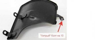
Next, attach the negative bolt (aka fastening bolt) to the body somewhere.
From the battery (through the fuse) you lead the plus to pin 30 of the relay, from 87 you feed the terminal on the signal.
And everything will work!
Instead of a jumper, you put a relay, and the polarity on the wires changes, then the wire that was “-” became “+”, and vice versa - which was “+” became “-“, you aim the + wire, bolt the ground onto the body, and there you have it joy:)
Hello. well, bring in your idea))) only with a little blood)))
read the PM! I will say this with very little blood
Hello. well, bring in your idea))) only with a little blood)))
I installed it myself, you take out the jumper and install the relay, now the wire that was ground has become a plus, you put the signal lights with a minus on ground, and the resulting plus goes to the signal lights, and everything is ok, if anything is not clear, ask.
just take a 3-pin Volgov relay and you will be happy;) you connect 2 stock wires to it, 3 lead to a signal
The whole problem is that in your wiring the signal is controlled by a negative signal (“-“). The minus is closed through the steering wheel.
In general, I wrote a detailed and simple article especially for such cases. www.drive2.ru/l/4514195/ - this one.
Your relay should fit the mounting block.
AND? buzzes without pressing the signal))))
I have already corrected my mistake)))) By deleting the comment))) I didn’t quite understand what kind of circuit it was, since I used a relay in the signal, I decided that I would still remain silent)))))
Isn’t it easier not to bother with the original unit, but simply connect the original wires (which go to the signal + and -) to the relay at terminals 85 and 86, and you can run one wire from the battery to terminal 30 through a fuse and, accordingly, another wire from terminal 87 on the new signals themselves. The relay can be placed under the hood along with the wires.