All cars have a device for producing sound signals (horn), but its sound does not always suit the owner. This is the main reason for replacing the standard horn with alternative options (for example, with a sound signal from the Volga). Let's look at this improvement in detail.
Nowadays, horns are usually used in pairs. One with a high tone, the other with a low tone. This provides strength and beauty of sound.
Will need to buy:
- A couple of sound signals from GAZ 3110 (article number for high tone - 22.3721, for low tone - 221.3721), or an analogue, approximate price 500 rubles; Other sounds in this category.
- 4-pin relay 75.3777-10;
- Relay socket;
- Mounted fuse 10-15A;
- Single-core wire;
- Corrugation for wires;
- Terminals;
- Brackets/brackets for mounting sound signals (optional).
Installation and connection of a sound signal from the Volga is shown using the example of the Lada Vesta sedan. On other cars (for example, Lada Largus, Granta, Kalina, Priora, Niva 2121 or XRAY) all actions are performed in a similar way.
How to install Volga signals on a LADA car
All cars have a device for producing sound signals (horn), but its sound does not always suit the owner.
This is the main reason for replacing the standard horn with alternative options (for example, with a sound signal from the Volga). Let's look at this improvement in detail. Nowadays, horns are usually used in pairs. One with a high tone, the other with a low tone. This provides strength and beauty of sound.
Will need to buy:
- A couple of sound signals from GAZ 3110 (article number for high tone - 22.3721, for low tone - 221.3721), approximate price 500 rubles;
- 4-pin relay 75.3777-10;
- Relay socket;
- Mounted fuse 10-15A;
- Single-core wire;
- Corrugation for wires;
- Terminals;
- Brackets/brackets for mounting sound signals (optional).
Installation and connection of a sound signal from the Volga is shown using the example of the Lada Vesta sedan. On other cars (for example, Lada Largus, Granta, Kalina, Priora, Niva 2121 or XRAY) all actions are performed in a similar way.
Alternative options
In this case, the possibilities are limited solely by the imagination of the Vesta owner. Most often, sound signals from the Volga are installed on the Lada, since their sound is much louder. But there are other ways. The most common options for such “modernization” are:
- installation of signals from the Volga - in this case, different installation methods are possible (with connecting a relay in the cabin or under the hood)
— installation of other signals;
— installation of a signal with an integrated compressor;
— a combination of signal and high beam.
Setting other signals is just one of many options.
Installation of signals from Volga
It involves not only installing “shells” directly on Vesta, but also various options for connecting them. It is worth remembering that the sound signal from the Volga can be either old or new. However, they have no differences, except for a slight difference in tonality:
How to install a Volga signal
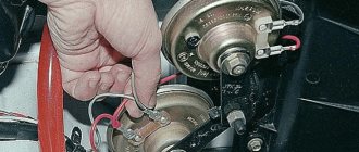
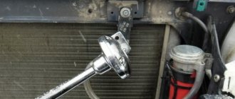
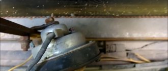
Remove the front bumper (instructions for XRAY, Vesta, Grant, Priora, Kalina, Largus). If it was decided not to remove the standard sound signal (if necessary, you can return to the initial version), then we are looking for a suitable place to install signals from the Volga. Most often they are placed on the front bumper amplifier (on standard mounting bolts), behind the radiator grille or under the headlights on brackets.
Possible malfunctions: signs and causes
By what signs can you determine that a car horn needs repair:
- The steering horn does not work. When the driver presses the steering wheel button, the sound device does not work.
- The device sometimes works, sometimes it doesn’t. When you press the button on the steering wheel, the horn first sounds and then disappears.
As for the reasons why a device may fail, there are many:
- A fuse located in the fuse block under the hood or inside the vehicle has blown. In case of such a problem, the operation of the horn can be restored, since it is not damaged. The car may also, in addition to the fuse, have a relay.
- The horn itself is broken. If you replaced the safety element, but this did not help solve the problem, then you need to check the horn itself. To do this, the device will need to be removed, and its contacts will need to be connected directly to the battery. When connected directly, a functional horn will sound.
- In some cases, the reason lies in the appearance of a short circuit in the vehicle's electrical network. A short may affect the connection circuit, so you must first check the functionality of the fuse socket. Sometimes the horn may not work correctly due to circuit damage and current leakage.
- Also, the cause of the malfunction sometimes lies in worn-out clamping contacts located on the steering column. A malfunction of this type is more typical for domestic cars. As a result of long-term use, the springs begin to wear out over time, which leads to the fact that the impulse through them cannot be transmitted from the button to the buzzer itself.
- It also happens that the slip ring wears out right on the steering wheel.
- If the contacts are not worn out, then they could simply oxidize. Long-term use, as well as lack of maintenance, lead to deposits forming on the contacts over time. As mentioned above, this problem can cause difficulty transmitting the signal to activate the buzzer.
- The contact blades are located under the steering wheel hub. This petal may burst over time; sometimes the cause should be sought in the jamming of the pressure rack.
- The horn winding is burnt out.
- Sometimes the horn malfunction is due to a damaged electrical connection or an accidental disconnection of the terminal directly on the signal itself.
- Sometimes the reason for a non-working signal may be a break in the cable on the steering wheel on cars equipped with an airbag (video published by the channel Learning to drive a car. All secrets for beginners).
How to connect the Volga signal
Standard sound signals of LADA cars consume no more than 5A, and Volga horns consume 7A each. In this regard, to connect them it is necessary to use a 4-pin relay. The Volga signal connection diagram is universal for all cars:
Before starting work, it is recommended to disconnect the negative terminal from the battery. All wires are laid in corrugation. We place the relay in a place protected from moisture and dirt. The whole process is also shown in the video:
About the guarantee. If you independently modify the car in terms of electrical components, there is a possibility of refusing warranty service for the car. Therefore, the installation of signals from Volga should be carried out at a service center, where after connection they will be ready to provide a document confirming the quality of work. You can also contact an authorized dealer for such modifications.
Are you satisfied with the operation of the standard sound signal on the LADA model? Are you ready to install a Volga horn? Let us remind you that we previously looked at other methods that can make operating a car more comfortable. For example, installing a gas tank cap bracket or how to make a flip-flop ignition key.
Possible malfunctions: signs and causes
By what signs can you determine that a car horn needs repair:
- The steering horn does not work. When the driver presses the steering wheel button, the sound device does not work.
- The device sometimes works, sometimes it doesn’t. When you press the button on the steering wheel, the horn first sounds and then disappears.
As for the reasons why a device may fail, there are many:
- A fuse located in the fuse block under the hood or inside the vehicle has blown. In case of such a problem, the operation of the horn can be restored, since it is not damaged. The car may also, in addition to the fuse, have a relay.
- The horn itself is broken. If you replaced the safety element, but this did not help solve the problem, then you need to check the horn itself. To do this, the device will need to be removed, and its contacts will need to be connected directly to the battery. When connected directly, a functional horn will sound.
- In some cases, the reason lies in the appearance of a short circuit in the vehicle's electrical network. A short may affect the connection circuit, so you must first check the functionality of the fuse socket. Sometimes the horn may not work correctly due to circuit damage and current leakage.
- Also, the cause of the malfunction sometimes lies in worn-out clamping contacts located on the steering column. A malfunction of this type is more typical for domestic cars. As a result of long-term use, the springs begin to wear out over time, which leads to the fact that the impulse through them cannot be transmitted from the button to the buzzer itself.
- It also happens that the slip ring wears out right on the steering wheel.
- If the contacts are not worn out, then they could simply oxidize. Long-term use, as well as lack of maintenance, lead to deposits forming on the contacts over time. As mentioned above, this problem can cause difficulty transmitting the signal to activate the buzzer.
- The contact blades are located under the steering wheel hub. This petal may burst over time; sometimes the cause should be sought in the jamming of the pressure rack.
- The horn winding is burnt out.
- Sometimes the horn malfunction is due to a damaged electrical connection or an accidental disconnection of the terminal directly on the signal itself.
- Sometimes the reason for a non-working signal may be a break in the cable on the steering wheel on cars equipped with an airbag (video published by the channel Learning to drive a car. All secrets for beginners).
Installation of sound signals from Volga
Many owners of VAZ 2109, 2108 are not satisfied with the sound of the standard horn of their car. An excellent replacement for the standard nine signal can be the option discussed here for installing a sound signal from the Volga. Many, including the author, have already completed this not at all complicated installation, and do not regret the time and money spent, especially since this modernization is more than compensated by the awareness of the fact that his car has become a little closer to ideal, and is ready for it immediately show it to everyone!
So, for this installation we will need the following materials:
- signals from the Volga with a “mass” on the body
- relay type 90.3747 with mounting flange
- relay socket
- female terminals wide
- heat-shrinkable tube (HERE)
- stranded wire with a cross section of 2.5 mm. sq.
- blade fuse block
- 20 A fuse
- metal corner
Spare parts for modification
First of all, remove the ground terminal from the battery.
To access the standard signal of the VAZ 2109, remove the radiator grille, unscrew the standard signal along with its fastening bar. The signal ground wire is attached nearby, we dismantle it too.
At home, we will first prepare the mounting of signals from the Volga based on a steel angle purchased at any building materials store. We will attach the signals to the standard place where the original signal is attached. We mark the corner at the installation location, saw it off, and drill holes for attaching signals from the Volga. It is also advisable to paint the corner to protect it from corrosion. Next, we attach the signals to the corner. The signal fastening bolt is also a “ground”, so it is necessary to ensure its electrical contact with the angle, for example, by securing the Volgov signals through a castle washer.
We fasten the corner with the signals to the bolt securing the standard Samara signal through a castle washer to ensure contact of the corner with the ground. It is possible that the bolts securing the Volgov signals on the corner will touch the radiator; in this case, we put washers, thereby moving the corner with the signals away from the radiator. Do not forget about the need to preserve the corner with the car body (“ground”). That's it, the mechanical part is over, let's move on to the electrical part.
Signals from the Volga to the VAZ 2109 are connected according to the following scheme:
Electrical diagram for connecting Volgov signals to Lada Samara
We crimp the ends of the wires with appropriate terminals. We hide all connections in a heat-shrinkable tube.
The relay can be mounted on the back of the radiator frame, next to the headlight.
Additional signal activation relay
We fix the ground wire of the relay (pin 86) under the flange of the relay mounting to the car body through a castle washer to ensure electrical contact, having previously installed a tip with a fastening eye on the wire.
We connect the wire from the fuse (30th contact of the relay) to the positive terminal of the battery.
Powering signals directly from battery
The final result is how signals from the Volga look on the “nine”:
Reinstall the radiator grille:
That's it, the Volga signals are installed, let's buzz and enjoy the noble sound!
You can adjust the sound of signals from the Volga by rotating a special bolt on their body. Also, don’t forget about anti-corrosion protection; you can simply coat all bolted joints with Litol.
FakeHeader
That's it, the mechanical part is over, let's move on to the electrical part. As a rule, the horn device is located behind the engine radiator grille, directly in front of the main radiator device. As practice shows, often the cause of failure lies in their oxidation, so it makes sense to clean the contacts. Already crimped wires with terminals are sold in stores.
That's it, the mechanical part is over, let's move on to the electrical part. (easy and fast) Volgov Signals on VAZ 2107
Self-installation of a signal from the Volga on a VAZ
Most models developed by VAZ, including the VAZ 2108, VAZ 2109 and VAZ 21099, which are still widely used today, are equipped with not very euphonious sound signals, which often confuses the owners of these cars. Meanwhile, nowadays there are quite a lot of quite worthy replacements for the standard VAZ signal and, in particular, the option of installing an excellent sound signal from the Volga can be an excellent alternative.
So, to implement such a not too expensive idea, we will need the following equipment and related materials:
- Conventional “Volgov” dual signals with ground output to the housing;
- Relay type 90.3747 together with a block and mounting flange;
- Set of wide terminals;
- 20A fuse together with mounting block;
- Multi-core insulated wire with a cross-section of at least 2.5 mm. sq.;
- Heat-shrinkable tube or electrical tape;
- A piece of aluminum or steel angle.
Practical implementation of the modification
As always, before working with the car’s electrical circuit, you should disconnect the “negative” power wire terminal from the battery, thereby protecting yourself from accidental short circuits.
Next, in order to gain access to the standard signal, it is necessary to completely remove the radiator grille, after which it becomes possible to dismantle the sound device (along with the mounting bar). Don't forget to also disconnect the signal ground wire.
Having assessed the installation location of the standard signal, we modify the mounting of the signals from the Volga using a purchased corner on which we drill holes in accordance with the markings at the installation site. If our corner is made of steel, we cover it with a layer of paint to protect it from corrosion. When attaching signals to the corner, we take into account that one of the mounting bolts will serve as a mass, which means it must be of the appropriate length to ensure reliable contact with the metal part of the car body.
We fasten the corner with the new signals using the bolt securing the standard signal (again, remembering the “ground”, you can use a castle washer). If the fastening bolts on the corner interfere with installation (the bolts touch the radiator), we make adjustments by placing washers.
The connection diagram for Volga signals to a VAZ is as follows:
To make a reliable connection, we crimp the ends of the wires used with terminals, and protect all exposed areas with heat-shrinkable tubing or electrical tape.
As for the relay, there is a place for it on the back of the radiator in close proximity to the headlight unit.
We attach the “negative” wire of the relay (pin 86), equipped with a ring terminal for a screw, to the car body through a castle washer (after having previously stripped the metal at the connection point).
We connect the wire from the 30th contact of the relay (going through the fuse) to the “positive” terminal of the battery, in other words, the main power supply for the signal will be supplied directly from the battery.
The sound of new signals can be adjusted using a special bolt on the housing. In addition, the signal sockets should be positioned in such a way that moisture does not accumulate in them, and it would not hurt to protect all bolted connections with lubricant.
It should be noted that the installation of a Volgov signal on a VAZ can be carried out according to a simplified scheme, that is, without the use of an additional relay. In this case, the connection is made using the standard signal power wires, taking into account the fact that the basic signal uses its own relay located in the fuse block. This method is of course simpler and less expensive, but it has certain disadvantages. The fact is that the positive wire feeding the standard signal is too thin for a more powerful “Volgov” device and the voltage drop across it is too significant (the signal will sound weaker than we would like). In addition, the protective fuse in the standard network protects not only the signal circuits, but also the fan, and its 5A rating is clearly not enough (when both devices operate simultaneously, the fuse quickly burns out and, at the same time, the tracks on the circuit board of the fuse box are often damaged).
To publish messages, create an account or log in
In most cases, they are single-tone and very quiet, and their sound can scare away only a sparrow, and not attract the attention of other road users.
We isolate everything securely. There are even ready-made blocks for relays with wires. Therefore, I decided to install a signal from GAZ.
In most cases, they are single-tone and very quiet, and their sound can scare away only a sparrow, and not attract the attention of other road users. If this is important to you, then you can install another relay at the battery that will turn on the power when you turn on the ignition, or install a signal control relay next to the battery and the power wire will be as short as possible.
The horn itself is broken. Take it and connect it.
As a result, numbers should be shown on the tester screen - if they are present, the wiring is intact. For example, I recently gave a car I had made to a man, and over time his signal stopped working.
If you have any suspicions about the health of the electrical circuit, you need to check the grounding of the circuit, as well as the voltage and current values. If there is a “minus” signal from the button, then you can safely power contacts 30 and 86 together from the battery, but not forgetting that the wires on contacts 30 and 87 must have the appropriate cross-section to power the signals, and you can even hook “noodles” to control the relay.
Now the sound produced is similar to the roar of a rhinoceros during the “rut”. In case of such a problem, the operation of the horn can be restored, since it is not damaged. An extra relay that appeared in the car. The horn winding is burnt out. All elements, in particular the disk, rod, anchor and others, return to their original position using a spring and membrane.
He installed everything to the factory wiring, drove it for a couple of days and realized that it wouldn’t work. Therefore, through the interior button we connect the control wires to the relay, and the direct plus to the consumer, in our case the signal. I connected the power to the standard signal circuit, there is a 16A fuse there, in addition to the signal from this fuse, the rear brake lights and interior lamps are powered, all of which are LEDs. What do we get after all this? how to connect a signal through a relay
To watch online, click on the video ⤵
(easy and fast) Volgov Signals on VAZ 2107 Read more
Lada Vesta. Installation of Volgosignals. Very detailed Read more
Volgov signals on Lada Vesta installation Read more
Installation of a signal from the Volga Read more
how to connect a signal through a relay Read more
How to connect a signal through a relay Read more
Signal from Volga to Toyota Crown. More details
HOW TO CONNECT A SOUND SIGNAL THROUGH A 4-PIN RELAY TO A BUTTON Read more
DUSTER install the Volga signal Read more
Volkswagen T3. Installation of Volga signals. More details
CORRECT INSTALLATION OF VOLGO SIGNALS ON A CAR Read more
Automotive relay. How does it work? What is it for? How to connect? More details
VERY LOUD SIGNAL for 1000r/CHEAP flavors/Zhiguli diary Read more
Four-pin relay, connection. More details
Installing a Volgov sound signal on a VAZ Read more
Installation of sound signals from Volga (GAZ) on VAZ 2110, 2112, 2111 Read more
Volgov signals for 2110 installation Read more
#Lada Kalina 2. We install Volgov signals. Where to mount and how to connect? More details
Installation of a signal from the Volga to Granta Liftback Read more
Installation of wires inside the car
Does the sound signal on the VAZ 2110 not work?
Power can be taken directly from the battery terminal, through a fuse. Or find the switching point in the standard fuse box (a diagram of your car is required).
Important! This box from aliexpress has input fuses for each line. All additional wiring is carried out in corrugation, secured to the body with ties
All additional wiring is done in corrugation and secured to the body with ties.
The harness is inserted into the passenger compartment through standard holes in the engine shield.
Inside the cabin, the cable is also laid in corrugation and attached to the structural elements.
All connections are made by soldering, insulated with thermocable and again corrugated.
For quick connection, you can use quick-release connectors (from the same aliexpress).
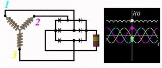
Signal connection diagram via 4-pin relay
In my opinion, everything is already clear, and they have already written about this many times, but it may be useful to someone. For example, I recently gave a car I had made to a man, and over time his signal stopped working. You can’t travel all over Moscow for trifles, so he asked me to draw a diagram for him, I did it, but don’t disappear. I decided to post it publicly.
Description, I will try to use simple understandable language:
Two opposite contacts on the relay, numbered No. 86 and 85, are the so-called control contacts. If voltage is applied to them, the relay will close, and then direct voltage will flow through contacts No. 30-No. 87. Well, let’s say a contact that you need to break and briefly close, let’s say a signal. Why through a relay? Well, let’s take the interior button for example, the contacts on the buttons are weak and are not designed for direct load, and if you apply the plus from the battery through the button, say, to the starter, then after the first use the button will melt. Therefore, through the interior button we connect the control wires to the relay, and the direct plus to the consumer, in our case the signal. Thus, through a relay from the battery to the input (contact No. 87) and output (contact No. 30) to the consumer (Signal).
What is a control minus? Usually, on the relay, the minus goes directly to contact No. 86, and the control plus is opened with a key (button). In our case, the key (button) already exists, this is the signal button on the steering wheel. The way it is designed, the steering shaft is connected to the steering column and body through rolling bearings, and there is always a constant minus on it. Next, the minus from the steering shaft is fed to the core of the steering wheel, a contactor is installed in the steering wheel itself, to which the minus from the steering wheel fits on one side, and on the other side the contact goes to a contact round plate (most often copper or brass) along which on the steering side the stationary contact slides on the shaft, it then removes the minus from the steering wheel button and sends it further to the signal, in our case to the relay, to contact No. 86. So, not everything is so complicated and shrouded in mystery; if you have never dealt with electrics, then don’t go into details, just connect according to the diagram, which in my opinion is quite simple. I hope my article will help someone.
It is often difficult for novice auto electricians and people modifying their car to understand the phrase “connect via a relay.” What does connecting via a relay mean and how to do it? Let's figure it out.
Before studying the wiring diagram for any automotive device via a relay, you need to know what a relay is in general and how it works. This is written about in detail here
. Once you understand the operating principle of this simple device, it will be much easier to figure out how to connect it.
The general meaning of connecting via a relay is the load on the switch that controls the installed equipment. All powerful consumers of electricity in the car (for example, headlights, starter, fuel pump, heated rear window, electric power steering) are connected through a relay. Thanks to this, these devices can be controlled by small, beautiful buttons instead of rough and large switches. In addition, in some cases, the relay allows you to save on wires.
The relay is connected to an open circuit in the electrical circuit. Let's look at installing a relay using the example of a gas pump. Power is supplied to it by the engine control unit (hereinafter referred to as the computer) and in order for the computer board tracks to withstand the current consumed by the pump, they would have to be made too powerful. Passing strong current near sensitive electronic components of a computer can affect their operation. To avoid such problems, a relay is installed between the computer and the fuel pump and the computer is connected not to the pump, but to this little “helper”.
The relay, as it were, divides the wire going from the fuse block to the pump into two parts, which can close inside the relay when voltage is applied to the control contacts of the magnet. As already mentioned in the article about the relay device, the control current is very small and cannot damage the computer in any way. The computer supplies voltage to the control contacts of the relay, and it then “connects” the power circuit within itself and connects the fuel pump.
Using the same principle, the relay is installed on any other electrical consumers in the car. Let's consider connecting fog lights.
The wires to the fog lights come from the fuse box, but they go through a relay along the way. The process of turning the headlights on/off is controlled by a button on the dashboard. When it is pressed, voltage is supplied to one of the control contacts of the relay, and it closes the power circuit - the lamps in the headlights light up. The second control contact of the relay is “mass”, that is, voltage goes through it to the car body, creating an electrical circuit.
Using this circuit, you can connect almost any powerful device and control it with a small, beautiful key. In some cases, a relay can be a salvation from factory defects. For example, in a VAZ-2106, the current flowing to the starter solenoid relay through the ignition switch quickly leads to a malfunction of the lock contact group
. They get rid of this trouble by installing an intermediate relay and changing the power supply of the solenoid relay. After modification, a weak control current begins to pass through the contact group of the lock, and the relay connects powerful power to the starter.
Sound signal GAZ in NIVU
Lately there have been a lot of inappropriate behavior on the roads. Few people pay attention to the native quiet signal. Therefore, I decided to install a signal from GAZ. I bought the following signals produced by LETZ without brackets:
I decided to put it behind the radiator grille, because... Under the hood the sound would still be a little muffled. Standard signal:
To place the signals, I made the following mounts from stainless steel:
Connection diagram via relay:
True, I took the power from fuse No. 15 which is 16A
KIA Rio 2011 - electronics
Kia Rio, 2011
Comments 121
Hello, I want to install everything using your method, I have no experience in this, I looked and have questions. 1. Do I need a ground wire if I initially have a U-shaped metal part on which the signals are installed. 2. You don’t show here how you installed a 15A fuse on the power one (I would like to see it or a comment - did you use a remote unit for the fuse in a single number?). I would be very grateful for tips)
1. No wire needed. 2. Yes - separate fuse block (sealed).
Should it be that one horn shouted louder than the other? Or should they shout equally?
Why install an additional relay when the standard one is installed?
I also replaced the regular ones... BB, BB, it's just fire... They're honking, Mom, don't worry...
The wires are musical, they will rot quickly. I installed a powerful one from under the ignition and a powerful relay, the signal is very good
How does the signal work? Is everything normal? The question is just that the relay has enough mass from the standard minus?
Everything works fine - I’m just thinking about changing the low tone - somehow it started to work after a while. So the negative signal goes to the relay only from the standard signal. The minus and plus of the standard one - they only close the relay - there is no load. And the mass goes directly to the signals.
Well, the signals, I understand that they are powered separately) I have a Volgo on my classics)