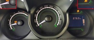
The main reasons why the speedometer does not work
There may be several reasons for the malfunction, but the main two are:
- Failure of the speed sensor.
- Short circuit of the radio wires.
The first problem can be fixed by yourself if you change the speed sensor itself. Experts do not advise correcting this error yourself if you do not have certain skills in carrying out such work. In this case, you can contact specialized services.
Closing wires
The speedometer may not work correctly or may not work at all due to the fact that the wires in the radio are shorted.
The whole point here is that the wires initially all pass through the radio, and after that they go to the instrument panel itself. Manufacturers made such a system so that the driver has the opportunity to automatically adjust the volume of the radio depending on the situation on the road.
It should be noted here that such a problem with wires exists only in older versions of cars that were produced before restyling. In new versions there is no such reason anymore.
If the radio was installed incorrectly, the wires that go to the panel can often be cut or damaged. This is what causes problems. To correct this situation, you need to remove the radio and connect the two wires (green). If this does not help, then the problem may be with the speed detector. The pointer drive, which is made of plastic, may also be damaged. But you won’t be able to fix such problems yourself. We need to visit the service station.
The speed sensor is acting up
Logan is equipped with parts with two types of contact arrangements:
To understand which one is needed, you need to initially disassemble the sensor and check it.
MR8200547283 - speed sensor article number (not suitable for everyone!)
It is worth noting that the price of components from the car manufacturer is quite high, and therefore experts advise choosing Romanian spare parts, the cost of which is lower. You can also use Korean components. But you need to be prepared for the fact that they will not last long. The sensor itself is located in the engine compartment on the gearbox. To change it, you need to perform the following actions.
Replacement process
- Remove the filter (air). You will need a head and a wrench. The sensor is located under the filter (it is possible without removing it, but this is not entirely convenient).
- Press on its fastening and, rocking, pull it out of its seat.
- Clean the area before installing a new sensor.
- Insert new spare part.
- Replace the filter.
After this, you need to check the operation of the part. If the problem has not been resolved and the speedometer does not work, then you need to call an electrician for help, as the problem may be in the instrument panel.
Signs of a part failure
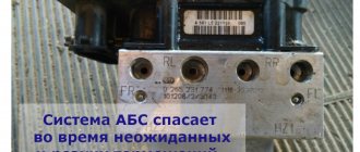
The driver can identify problems with the ABS system by the warning light on the instrument panel. If there are problems, the lamp will light or blink. This is the first sign of a problem.
In this case, it is recommended to connect a diagnostic tool and accurately determine the cause of the malfunction. For example, the Rokodil ScanX scanner is capable of not only determining the error of the ABS sensor, but also accurately indicating on which wheel it is located.
Also in case of any malfunction:
- Possible wheel locking during sudden braking;
- There will be no vibration when you press the brake pedal.
conclusions
Knowing the reasons why the speedometer on a Renault Logan usually fails, you can identify them yourself and fix them.
The speed sensor of the Lada Largus car is installed on the gearbox. It outputs a pulse signal to the electronic engine control unit, proportional to the speed of rotation of the secondary shaft of the gearbox. The principle of the sensor is based on the Hall effect, that is, the occurrence of EMF in the event of a change in the magnetic field around the sensor.
To remove the Lada Largus speed sensor, you do not need any tools other than a screwdriver.
Crankshaft position sensor (CPS)
The sensor provides the control unit with information about the speed and angular position of the crankshaft. Based on the sensor signals, the ECU calculates the phase and duration of the control pulses for the injectors and ignition coil. If it malfunctions (no signal), the engine will not start. It is located in the tide hole of the oil pump cover.
Designed to generate a signal by which the ECU determines the top dead center of the piston of the first cylinder during the compression stroke. The operating principle of the sensor is based on the Hall effect. If the sensor is faulty, the ECU switches the system to backup mode. The engine may run erratically, stall, or have difficulty starting. DPRV cannot be repaired. If it malfunctions, it is replaced with a new one.
Operations to remove the Lada Largus speed sensor
1. Disconnect the wire from the negative terminal of the battery. 2. Press the latch and disconnect the wiring harness block from the speed sensor.
3. Carefully pry the sensor with a screwdriver and remove it from the hole in the gearbox housing (the sensor housing is installed with an interference fit in the gearbox hole and sealed with rubber rings).
4. Install the speed sensor in the reverse order of removal.
Using snap ring pliers, remove the bearing snap ring from the steering knuckle groove.
Use a cup puller to press the bearing out of the steering knuckle.
The bearing can also be pressed out by impact. To do this, we rest our fist on the jaws of the vice.
By striking the end of the outer ring of the bearing through a mandrel or head of a suitable size, we press the bearing out of the fist.
Bearing installation
Before installing a new bearing, clean the mounting hole in the steering knuckle and the groove for the retaining ring. Using a needle file, we clean out the nicks from the chisel on the hub.
Before pressing the bearing, we insert the mounting ring of the wheel speed sensor into the hole of the steering knuckle (with the paws centering the ring, inside the knuckle).
We orient the ring in the hole of the fist so that the speed sensor holder on ring 1 (Figure 13) is located in the groove of fist 2 (for clarity, shown on the assembled hub assembly).
After installing the cup puller screw with the support washer, insert a new bearing into the hole in the knuckle.
On a vehicle with ABS, the bearing should be installed so that its dark-colored protective washer (made of magnetic material) faces the wheel speed sensor mounting ring.
Figure 15 shows the details of the hub assembly.
Diagnostics
Checking the controller can be done in several ways; we recommend that you familiarize yourself with each of them in more detail. For the first two methods you will need a voltmeter.
First way:
- First, the sensor must be removed. Find its installation location, disconnect the connected connector, unscrew the fixing nut and remove the device from the mounting location.
- Then take a voltmeter and figure out the pinout of the connector. The connector has three contacts, the first of which is usually a positive contact, the second is an output signal, and the third is a negative contact. One of the tester probes should be connected to contact number 2, and the second probe should be grounded - connected to the engine body or car body.
- Afterwards, you need to rotate the controller to determine whether there are pulses in the operating cycle and measure the output voltage. To do this, you need to install a piece of pipe on the sensor axis and rotate the device at a speed of approximately 3-5 km/h. The voltage and frequency in the tester depend on the rotation speed of the controller (the author of the video is Artem Kulzhanov).
The second diagnostic option is performed without dismantling the sensor:
- You need to put the car on a jack. You need to jack up the front of the car so that one of the wheels is hanging out and not in contact with the ground.
- After this, the tester probes must again be connected to the contacts on the device connector.
- The hanging wheel must be rotated and at the same time monitor the readings on the tester display. If, as a result of rotation, voltage and frequency appear, measured in hertz, then this indicates the operability of the device.
There is another checking option; to perform it you will need a light bulb or control.
Diagnostics is performed as follows:
- First of all, you should disconnect the plug and wiring from the sensor.
- Using the control, you will need to find the plus and minus, before that you need to turn on the ignition.
- Next, as in the previous method, you need to put the front of the car body on a jack and hang one wheel.
- Now you should connect the control pin to the pulse contact of the sensor (usually it is the middle one) and rotate the wheel by hand. If at the same time the minus lights up on the control panel, this indicates that the device is working. Alternatively, instead of a control, you can use a light bulb with a connected wire, one of which is connected to the battery, and the second to the signal connector. If the light begins to blink when the wheel rotates, then the controller is working (video shot by Alex Kov).
Front wheel speed sensor (ABS sensor) - removal and installation
Note: Do not confuse the wheel speed sensor with the vehicle speed sensor.
Front wheel speed sensor
This is what the sensor looks like in the hub assembly (steering knuckle): 1 – speed sensor mounting ring; 2 – inner ring of the front hub bearing; 3 – front wheel speed sensor; 4 – wheel hub; 5 – steering knuckle
Wheel bearing with sensor: 1 – magnetic bearing washer; 2 – speed sensor; 3 – hub bearing; 4 – speed sensor mounting ring
Jack up the car and place it on reliable stands, or place it on a two-post lift, apply the parking brake and turn off the ignition.
(Raise the car to a height convenient for performing work).
1 — bracket for fastening the speed sensor wiring harness; 2 — fender liner clamp; 3 — front wheel arch liner; 4 — front wheel speed sensor; 5 — bracket for fastening the speed sensor wiring harness on the front suspension strut; 6 - steering knuckle
Remove fastener 2, Figure 21-2, front wheel arch liner in the area where the speed sensor wiring harness is located (flat-head screwdriver).
Note: For ease of operation, you can remove the front fender liner (see here)
Remove the speed sensor wiring harness from the grooves in bracket 5 of the front suspension strut and from holder 1 on the mudguard of the engine compartment.
Remove insulating foam 1, Figure 21-3, from the knuckle speed sensor mounting socket (optional).
Figure 21-3 — Removing the front wheel speed sensor:
1 - insulating foam; 2 — front wheel speed sensor; 3 - latch
Remove speed sensor 2 from the mounting hole on the steering knuckle by using a screwdriver to press out the locking tab of sensor 3 (flat screwdriver).
Disconnect the speed sensor wiring harness connector from the front wiring harness and remove the sensor.
Attention. The insulating foam material of the wheel speed sensor must be replaced.
Install insulating foam into the speed sensor mounting slot on the steering knuckle.
Connect the speed sensor wiring harness connector to the wiring harness
Install the speed sensor into the mounting hole on the steering knuckle until the latch engages.
Install the speed sensor wiring harness into the grooves of the front suspension strut bracket and into the holder on the mudguard of the engine compartment.
Secure the front wheel arch liner with the clamp.
Install the front wheel.
Video
Source
Purpose of relays and fuses in the mounting block located in the engine compartment
Note: The location of relays and fuses in the engine compartment may vary depending on the installed engine and vehicle modification.
LOCATION ON K4M ENGINE MODELS
K - Relay, F - Fuses
CIRCUIT BREAKERS
| Fuse designation (rated current, A) | Protected elements |
| F1 (15) | Not used |
| F2 (5) | Circuits: constant power supply to the engine control system ECU; windings of the main relay K5 of the engine control system |
| F3 (25) | Power circuits: relay K4 of the fuel pump and ignition coil; main relay K5 of the engine management system |
| F4 (30) | Cooling fan short circuit relay power circuit (on a vehicle without air conditioning) |
| F5 (40) | Power circuits: air conditioning relay K2; low speed short circuit relay for the cooling system fan (on a car with air conditioning); relay K1 high speed cooling fan (on a car with air conditioning) |
| F6 (25) and F7 (50) | ABS control unit circuits |
| F8 (60) | Circuits: power supply to the ignition switch and all consumers powered from the lock; left steering column switch |
| F9 (60) | Interior fuse box power supply circuit |
RELAY
| Designation | Name | Powered consumers |
| K1 | Cooling fan high speed relay (for vehicle with air conditioning) | Cooling fan motor |
| K2 | Air conditioner relay | Air conditioning compressor electromagnetic clutch |
| short circuit | Low speed cooling fan relay (for vehicle with air conditioning) or cooling fan relay (for vehicle without air conditioning) | Cooling fan electric motor (for a car with air conditioning - through a resistor) |
| K4 | Fuel pump and ignition coil relay | Fuel pump and ignition coil |
| K5 | Engine control system main relay | Oxygen concentration sensors (heating circuit): speed sensor; fuel injectors; adsorber purge solenoid valve; relay windings K1. KZ, K2; Engine control ECU |
| K6 | Not used | — |
| K7 | Fog light relay | Fog lamps |
| K8 | Heater Fan Relay | Heater fan motor |
LOCATION ON MODELS WITH VAZ-11189, VAZ-21129 ENGINES
CIRCUIT BREAKERS
*Only with engine 11189
**Only with engine 21129
RELAY
Other location options
| Relay/fuse panel number | Relay/fuse number | Relay/fuse assignment |
| 299-1 | 231(A). | Fog light relay |
| 753(B) | Headlight washer pump relay | |
| 299-2 | 233 | Heater Fan Relay |
| 597-1 | F1 (60 A), F2 (60 A) | Electronic control unit for ABS and ESP systems |
| 597-3 | F1 (50 A). F2 (25 A) | Exterior light switch, interior fuse box |
| 784 | 700(A), | Cooling fan relay |
| 474(B) | Air conditioning compressor relay | |
| 1047 | F1 (30 A), | Relay box power supply |
| F2 (25 A) | Injection relay power supply | |
| F3 (5 A), | Power supply for injection system relay, ECU | |
| F4 (15 A) | Not used | |
| 238(A). | Injection blocking relay | |
| 236(B) | Fuel pump relay |
The ABS light on the LADA came on, how to fix the problem
10 April 2022 LadaOnline 68 579 Currently, all LADA models (Lada XRAY, Vesta, Largus, Granta, Kalina, Priora, Niva 4×4) without exception are equipped with ABS (anti-lock braking system). During the operation of the car, many owners notice that the ABS and ESC lamps (if this system is available) light up on the instrument panel. Let's figure out how to solve this problem and improve the design.
Why does the ABS and ESC light come on?
ABS malfunction may be caused by:
- failure of wheel rotation sensors;
- malfunction of the hydraulic valve block;
- damage to the wiring.
If the ABS malfunction indicator light comes on, you must contact a service station as soon as possible for diagnostics (read error codes) and repairs.
The most common cause of ABS failure is damage to the wiring near the ABS sensor connector. It is located under the fender liner, but is still not well protected from moisture and dirt.
As a result, the wires oxidize and break, and the ABS lamp lights up.
How to repair wiring
We remove the wheel, and then the locker (for the front wheel, turning out the fastening screws) or the protective shield (for the rear wheel, turning out the two fastening nuts “10”). Press the latch and disconnect the block with wires from the ABS sensor. We inspect the connector and make sure there is no corrosion or damage. In case of damage, we restore the integrity of the wires:
We treat it with a special means for cleaning electrical contacts (for example, graphite grease) and clean the contacts from oxides. We clean the wheel speed sensor and the surface around the sensor from dirt.
Attention! Keep ABS sensors away from magnets as this may cause damage.
Replacing ABS sensors
If the cause of the malfunction is not in the wiring, but in the ABS sensor itself, we replace it. To do this, first unscrew the fastening screw with a Torx T30 key, and then remove the sensor wiring harness from the bracket. The photo shows a Lada Vesta car; on other Lada models the work is performed in a similar way.
Instructions for replacing the front wheel ABS sensor:
Instructions for replacing the rear wheel ABS sensor:
How to modify the design
To protect the wiring harness from the environment, you can use a D-shaped seal. We lay the wires in it and wrap it with electrical tape. We put everything in the corrugation. We glue the cover covering the ABS sensor connector around the perimeter with the same sealant. This will prevent moisture and dirt from entering the area where the sensor and connector are located.
Attention! If the ABS fails, the brakes remain operational, but the braking efficiency is reduced, which is especially dangerous on some surfaces. See why
Photo: MATUR777 in-flight magazine
Keywords: lada xray sensors | Lada Vesta sensors | Lada Largus sensors | Lada Granta sensors | Lada Kalina sensors | Lada Priora sensors | Niva sensors | safety lada xray | safety of Lada Vesta | safety of Lada Largus | safety of Lada Granta | safety of Lada Kalina | safety of Lada Priora | Niva safety | Lada Xray brakes | Lada Vesta brakes | Lada Largus brakes | Lada Granta brakes | Lada Kalina brakes | Lada Priora brakes | Niva brakes | universal article
7 0
Found an error? Select it and press Ctrl+Enter..
Similar materials
- Reasons why the backlight of the Niva instrument panel does not light up (VAZ 2121, 2131)
- Description of the instrument panel Lada Priora and Kalina
- Why does the speedometer not work on Lada Granta, Kalina or Priora?
xn--80aal0a.xn--80asehdb
ABS repair — Lada Priora Hatchback, 1.6 l., 2008 on DRIVE2
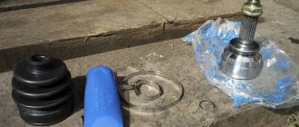
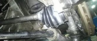
So I continued to look for the cause of the ABS malfunction. To begin with, I decided to make an appointment with the officials and carry out diagnostics. Moreover, I also got involved in a promotion where the entire car was shaken up for just 640 rubles. They ordered both front sensors to be replaced. Another problem was immediately discovered that was not related to my visit to the service. The right CV joint boot is torn. Since I crawled under the car a couple of days ago and everything was intact, and the tear looked fresh and clean, we decided to make do with replacing only the boot itself. Satisfied with the timely repair and diagnostics, which put everything in its place, I went home.
Then the search began for these same sensors. I was still haunted by the thought of whether it was possible to bring him to his senses. It’s just strange that a sensor of this type broke down, and on both wheels. I googled, read brilliant manuscripts on how to restore sensors, of course, according to reviews, they are not durable, but once again I climbed in the wheel arch in search of a hidden break or wear, and re-measured their contacts with new ones. A break and that's it. So the restoration plans failed. I started looking for new sensors. The price tag generally varies from 1400 to 1600 kopecks, which is somehow not at all budget for this car. The cheapest thing we could find was from the same officials for 1200 and in another store, the officials will deliver it only by the middle of the month. So I decided to buy it from the store.
I drove it, took it, well, I think you’ll make money from me in a minute. I was too lazy to change it myself because the weather is complete trash with snowfall, and it’s well known how these sensors get damaged. So I decided to entrust this disgrace to trained people. I went to the service. As it turned out, it won’t be easy for them to change these sensors either. Plus, it turned out that on both wheels the mounting brackets for these same sensors were bent, as a result of which they rubbed against the comb and stopped showing signs of life. I had to remove the calipers and brake discs in order to get to the bracket bolts. When removing it, it turned out that the left caliper bracket was held in place by one bolt, and the second was simply in place, but there was no thread there. So I splurged another 600 rubles for the bracket and 600 for the brackets. Well, here’s a photo of the removed brackets and sensors.
Well, after that, of course, everything came together perfectly. Upon startup, the ABS fault icon immediately went out and the brakes started working as they should.
Issue price: 4,000 ₽
www.drive2.ru
Change or repair
As a result of diagnosing the device, it is possible to determine which sensor node is damaged. If the tester readings tend to zero, this indicates a short circuit in the connection wires; “infinity” indicates a violation of the integrity of the coil winding. There is an opinion that repairing wiring does not cause any problems, but a faulty sensor is easier to simply replace. It’s hard to disagree with the first thought, but the next “point” can be disputed.
The fact is that the cost of some sensors reaches 14–18 thousand rubles, and you will have to wait for their delivery for a long time. Having certain skills, a reserve of patience and natural ingenuity, it will be much more useful and faster to repair the device than to pay for a long-awaited expensive order. Please note that this advice is only advisory in nature - the final verdict remains yours. If the decision to repair has been made, we will be happy to help you carry it out correctly.
Problems when paying with bank cards
Sometimes difficulties may arise when paying with Visa/MasterCard bank cards. The most common of them:
- There is a restriction on the card for paying for online purchases
- A plastic card is not intended for making payments online.
- The plastic card is not activated for making payments online.
- There are not enough funds on the plastic card.
In order to solve these problems, you need to call or write to the technical support of the bank where you are served. Bank specialists will help you resolve them and make payments.
That's basically it. The entire process of paying for a book in PDF format on car repair on our website takes 1-2 minutes.
The anti-lock braking system (ABS) prevents the wheels from locking when braking, eliminating the risk of losing control of the vehicle and maintaining its stability when driving. Due to its reasonable cost, this equipment is widely installed on modern automotive vehicles. An important role in the operation of the system is played by touch sensors that are mounted on the hubs and record the speed of rotation of the wheels.
Brake pad replacement process
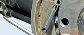
To replace the rear brake pads of the Lada Largus, you need to prepare tools. For work you will need: a jack, a wheel wrench, pliers and a flat-head screwdriver. When everything is prepared, you can proceed directly to the process:
- Engage 1st or 3rd gear at the gearbox.
- Place wheel chocks under the front wheels.
- Raise the rear of the car, where the pad will be changed, using a jack.
- We dismantle the wheel.
- Remove the cap from the brake reservoir.
- We dismantle the top cover of the brake drum.
- We move the working piston inward and fix it in this position.
- We squeeze the sliding parking brake levers inward.
- Compress the spring and unhook the handbrake cable.
- Turn the pressure spring a quarter. In this case, it is worth holding the support stand.
- Now, you can remove the cup, spring and support post.
- All operations described below must be done with the second block in the same drum.
- By stretching the upper spring, we remove the pads from the slots.
- Now, stretch the lower spring and remove the pads from the restrictor plate.
- Next, we dismantle the pads along with the springs.
- We unhook the springs from the pads, first the upper one, and then the lower one.
- Now, it is necessary to dismantle the spacer strips.
- Next, we inspect the drum for defects: chips, grooves, grooves.
- Now that everything is ready, install everything in reverse order.
- If necessary, add fluid to the brake reservoir.
Before using the handbrake, right in the garage, it must be gently pulled and released several times. This will help the new pads adjust.
