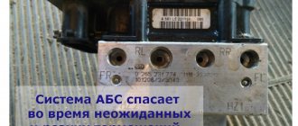
Currently, all LADA models (Lada XRAY, Vesta, Largus, Granta, Kalina, Priora, Niva 4×4) without exception are equipped with ABS (anti-lock braking system). During the operation of the car, many owners notice that the ABS and ESC lamps (if this system is available) light up on the instrument panel. Let's figure out how to solve this problem and improve the design.
Signs of a malfunctioning ABS sensor
The first sign of an ABS malfunction is a lit indicator on the instrument panel that does not go out for more than 6 seconds after turning on the ignition, or does not turn on when driving. A system breakdown is detected when the vehicle is moving at a speed of more than 25 km/h. There are quite a few problems that can happen with the anti-lock braking system, but the most common ones include the following:
- ABS sensor wire is broken or the controller unit is damaged. In this case, an error is displayed on the instrument panel, the system is turned off, and signals about changes in angular velocities are not given.
- The wheel sensor of the system has failed. When turned on, the system performs self-diagnosis and detects an error, but continues to function. The cause of the breakdown may be oxidation of the contacts, poor power supply to the sensor and a short circuit to ground.
- Receipt from an additional device of information about different angular speeds of wheels at different tire pressures or different tread patterns, when the wheels brake differently.
- Mechanical failure of elements - hub bearings, play and fracture of the rotor on the wheel sensor. In case of such failures, the system does not start. This also includes ABS pump failure.
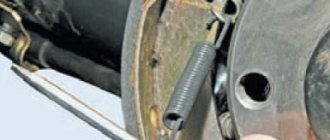
The most vulnerable element of the system is the wheel sensor, which is located next to the rotating hub and axle shaft. Exposure to dirt and play in the hub bearings can damage the device, completely blocking the operation of the ABS. Along with the indicator signal on the instrument panel, the following signs indicate a sensor failure:
- The on-board computer displays an ABS system error code.
- There is no characteristic vibration or sound when pressing the brake pedal.
- The wheels lock during emergency braking.
- Appearance of the parking brake signal when it is disabled.
Main types
The ABS sensor is read as the primary measuring part of the anti-lock braking system.
The device consists of:
- A meter placed permanently near the wheel;
- An induction ring (rotation indicator, impulse rotor) installed on a wheel (hub, wheel bearing, CV joint).
The sensors are available in two versions:
- Straight (end) cylindrical shape (rod) with a pulse element at one end and a connector at the other;
- Angled with a connector on the side and a metal or plastic bracket with a hole for a mounting bolt.
Two types of sensors are available:
- Passive - inductive;
- Active - magnetoresistive and based on a Hall element.
ABS allows you to maintain controllability and significantly increase stability during emergency braking
Passive
They are distinguished by a simple operating system, but are quite reliable and have a long validity period. Does not require a power connection. An inductive sensor is essentially an induction coil made of copper wire, in the middle of which there is a stationary magnet with a metal core.
The meter is located with the core to the pulse rotor in the form of a wheel with teeth. There is a certain gap between them. The rotor teeth are rectangular in shape. The opening between them is equal to or slightly larger than the width of the tooth.
While the vehicle is in motion as the rotor teeth pass near the core, the magnetic field penetrating the coil is constantly changing, forming an alternating current in the coil. The frequency and amplitude of the current are directly dependent on the speed of the wheel. Based on processing of this data, the control unit issues a command to the magnetic valves.
The disadvantages of passive sensors are:
- Relatively large dimensions;
- Poor accuracy of readings;
- They begin to function when the car picks up speed over 5 km/h;
- Triggered by minimal wheel rotation.
Due to frequent errors, they are installed extremely rarely on modern cars.
Magnetoresistive
The work is based on the property of ferromagnetic materials to change electrical resistance when exposed to a constant magnetic field.
The part of the sensor that controls changes is made of two or four layers of iron-nickel plates with conductors applied to them. Part of the element is installed in an integrated circuit that reads changes in resistance and generates a control signal.
The impulse rotor, which is a magnetized plastic ring in places, is rigidly fixed to the wheel hub. During operation, the magnetized sections of the rotor change the environment in the plates of the sensitive element, which is recorded by the circuit. Its output produces pulsed digital signals that enter the control unit.
This type of device controls the speed, direction of rotation of the wheels and the moment they come to a complete stop.
Magnetoresistive sensors record changes in the rotation of vehicle wheels with great accuracy, increasing the efficiency of safety systems.
Based on Hall element
This type of ABS sensor operates based on the Hall effect. In a flat conductor placed in a magnetic field, a transverse potential difference is formed.
Hall effect - the appearance of a transverse potential difference when a conductor with direct current is placed in a magnetic field
This conductor is a square-shaped metal plate placed in a microcircuit that includes a Hall integrated circuit and a control electronic system. The sensor is located on the opposite side of the pulse rotor and has the form of a metal wheel with teeth or a plastic ring, magnetized in places, rigidly fixed to the wheel hub.
The Hall circuit continuously produces signal bursts of a certain frequency. At rest, the signal frequency is reduced to a minimum or dies out completely. During movement, magnetized areas or rotor teeth passing by the sensing element cause changes in the current in the sensor, which are recorded by the tracking circuit. Based on the received data, an output signal is generated and sent to the control unit.
Sensors of this type measure speed from the beginning of the vehicle’s movement and are distinguished by the accuracy of measurements and the reliability of their functions.
How to use a tester to check the ABS sensor for functionality
Causes and Symptoms of faulty spark plugs and ignition coils.
Signs of faulty ignition coils Its performance can be checked using a multimeter. To do this, you need to move the multimeter to the “diode” position. Why? Most ABS sensors in the circuit have protection in the form of a diode connected in series with the circuit. That is, a regular call can lead to incorrect information.
It must be “ringed” in both directions. Typically, the resistance of the ABS sensor ranges from several hundred ohms to 2 kiloohms.
However, testing the sensor directly from its connector does not provide complete information about the passage of its signal to the ABS unit.
In many cases, the cable connecting the sensor connector to the ABS unit is damaged. Such malfunctions are especially common for rear wheel ABS sensors, since the cable length can be more than 3 meters, and manufacturers do not always design its routing correctly.
During the repair of ABS systems, there are cases of up to three fractures or rubbing of the anti-lock braking system sensor cables.
In order to check the sensor from the ABS control unit, you need to find the pinout (connection) of the connector in reference books or on the Internet. Next, you should disconnect the connector from the block and ring the ABS sensors directly from the connector contacts, as shown in the example:
If, as a result of checking with a multimeter, the ABS sensor rings in one or both directions, this is not evidence of its serviceability.
Structurally, it is made in the form of an inductance coil placed in a magnetic core. The coil has a large number (up to several thousand) turns of very thin insulated wire.
Often moisture gets inside the sensor, and this is very likely, since it is located in the most corrosion-prone area in the immediate vicinity of the wheels. Water, especially saline solution, can cause interturn short circuits. In this case, the winding resistance will change slightly, but the quality factor drops tens of times. This leads to a decrease in the signal level of the ABS sensor and its inoperability.
Very often during operation, especially after replacing hub and wheel elements, the ABS fault light starts to light up. lack of signal from the ABS sensor, for example, the right front wheel.
The owner replaces it based on diagnostic readings, but the ABS system remains faulty. Sometimes, after removing the error with the scanner, the malfunction light goes out, but as soon as you drive a few hundred meters, make a couple of brakes, it lights up again.
The issue here is not the sensor, but the design features of the signal formation (induction) of the wheel rotation sensor.
When to change pads
The frequency of replacing rear pads is 2 times less than the front ones. Since they have less load when braking.
On average, the mileage they can cover without replacement is 60-90 thousand km. Of course, these figures are approximate, since the operating conditions and driving style of each driver are individual. There are cases where the pads can be worn out by 30,000 km.
It is necessary to change the pads if:
- The thickness of the lining is less than 1.5mm. With such a thickness, the block no longer performs its functions and is simply not able to effectively brake the car.
- The overlay begins to peel off from the base. Using a pad with such problems is unacceptable. The pad can come off and get caught in the rotating parts, causing the wheel to wedge.
Lining Thickness
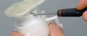
There is no need to remove the drum to check the thickness of the lining. You just need to remove the special rubber plug behind the drum and assess its condition.
Plug for checking the condition of the rear pads
Design features and malfunctions of ABS
Crankshaft position sensor, testing methods, symptoms of malfunction, location
The principle of operation of the sensor is based on recording information regarding the speed of rotation of the wheel, with subsequent transmission of data to the central organ of the system. The control unit analyzes the received parameters and issues commands to the elements of the vehicle’s hydraulic system. Thanks to timely changes in fluid pressure in the brake system, wheel locking is prevented when the brake is pressed.
Despite its reliability, the ABS sensor fails from time to time, which is why the control unit receives incorrect signals, or they do not reach it at all. In such a situation, it is necessary to check the ABS sensor and then replace the device (if a breakdown is detected).
The most common problem is a break in the supply circuit between the control unit and the monitoring sensor. It is also possible for the sensor to fail, followed by the transmission of distorted information.
Recognizing a problem with ABS is not difficult. It manifests itself by the glow of the corresponding light bulb during movement. In this case, accurate diagnosis is possible only after checking the device. Before deciding to replace or check the sensor, determine whether the system is working or not.
A breakdown can be recognized by the following signs:
1. The system is tested, after which an ABS error is detected. Probable causes are malfunctions in the controller, lack of signals from the angular velocity measurement sensor.
2. After activating the ABS, the system is tested and a breakdown is detected. The device continues to operate. This is possible if there is a malfunction of the ABS sensor, for example, if it breaks.
3. The system undergoes diagnostics and turns off. Probable causes are a break or poor quality of contact connections, or a short circuit of the sensor to the body.
4. ABS does not work at all. This is possible due to irregularities in the wiring (for example, a broken wire in the sensor power circuit), wear of the wheel bearings, damage to the wheel sensors, and so on.
Why pneumatic
Communities Lada Priora Lada Priora Club Blog Ignition switch wires
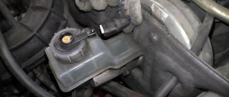
Braking requires quite a lot of effort from the driver. Making such an “injection” and bleeding the brakes on four wheels at once is not an easy task. Therefore, a solution was found: due to the vacuum in the intake system, a special mechanism, a vacuum, greatly facilitates this process. And the pedal is quite easy to press.
Important! It is the system, operating on the “syringe” principle, with many rubber seals, that requires the complete absence of air in the system, since its presence reduces the efficiency of the brakes to zero. Simply put, due to the difference in the density of air and brake fluid, instead of uniform pressure on the piston of the working cylinder, you will get a chaotic movement of air bubbles inside the system
Because of this, they sometimes need to be pumped
Simply put, due to the difference in the density of air and brake fluid, instead of uniform pressure on the piston of the working cylinder, there will be a chaotic movement of air bubbles inside the system. Because of this, they sometimes need to be pumped.
How to replace an ABS sensor at home
Signs of a malfunction of the mass air flow sensor
1. Remove the wheel, put the car on the handbrake, and install supports under the body.
2. Remove the “-” terminal of the battery or remove fuses F5 and F6 from the fuse block.
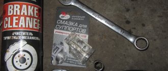
3. Treat the sensor and its mounting with WD-40.
4. Unscrew the sensor mounting bolt.
5. Disconnect the power connector.
6. Install a new ABS sensor and put everything back together. After assembly, check to see if the ABS fault indicator is on.
Some useful tips to avoid problems with ABS sensors
- Before disconnecting the sensors, always remove fuses F5, F6.
- When replacing wheel bearings, remove the ABS sensors.
- Install wheel bearings very carefully so as not to damage the magnetic ring. The bearing itself must fit clearly, without gaps or distortions, otherwise problems with the ABS sensor may occur.
- When repairing the chassis, make sure that the sensor wiring is securely insulated and does not come into contact with rubbing parts.
- From time to time, inspect the power wires, as well as the sensors themselves, for damage and breaks.
That's all for me, I hope this article will help you solve your problem. All the best and see you again at Ford Master.
ABS device on Priora
Like most modern car systems, ABS is computer controlled. But in addition to the electronic control unit, it also includes several sensors and actuators. The entire system consists of several elements.
- Electronic control unit (ECU).
- Sensors on wheel hubs 4 pcs.
- Brake fluid pressure valves in the system 4 pcs.
- EVN (Electric Return Pump).
- Warning light on the instrument panel.
Despite all its apparent simplicity, this is a rather complex, high-tech system. Each sensor transmits data on the rotation speed of the Priora wheel to the electronic control unit. Based on the data received, the control unit sends a signal to the brake system valve, which, when you press the brake pedal, releasing pressure, prevents the wheels from completely locking and starting an uncontrolled skid of the car.
Anti-lock brake control unit in hydraulic unit
Structurally, on the Priora, the ABS ECU is mounted together with the EWH and valves that regulate the pressure into a single unit - the hydraulic unit. It is located on the front left side member of the vehicle. The hydraulic unit is connected to the entire system by a common wiring harness. It includes pipes for supplying brake fluid to the working cylinders. An EWH is also installed here, increasing the pressure in the system.
Wheel hub sensor
The sensors that supply wheel speed data to the control unit are made on the principle of a Hall sensor. By the way, most rotation sensors use exactly this principle: changing the voltage on the semiconductor of the sensor, depending on the passage of a control point on the rotating disk near it. It is in correlation with the signals from the ABS sensors that the control unit manipulates the valves.
ABS malfunction warning lamp on the Priora instrument panel
What Priora drivers talk about – “the ABS sensor has come on” – is in fact a warning lamp for the serviceability of the anti-lock system. When the ignition is turned on, the orange “ABS” inscription will light up on the dashboard for about three seconds. If the system is working properly, then after three to four seconds the light will go out. In general, the principle of signaling from the “ABS sensor” is the same as from the warning lamp of the main ECU of the car, the well-known “check anger”.
practical guide
Anti-lock braking system
1. We prepare the car for work.
2. Remove the rear wheel.
3. Using a TORX E8 socket wrench, unscrew the sensor mounting bolt.
4. Remove the sensor from the brake mechanism shield. Continue reading →
1. We prepare the car for work.
The following procedure is not required to replace the right wheel speed sensor.
2. Remove the air filter.
3. Using a thin slotted screwdriver, press the latch and disconnect the sensor wiring harness block (the block is secured in the front part of the left side member).
4. Push down the pad lock Read more →
To check the technical condition of the anti-lock brake system (ABS), a warning lamp is installed on the instrument panel. An ABS malfunction may be caused by a failure of the wheel rotation sensors or a malfunction of the hydraulic valve block itself. If the ABS fails, the braking system remains operational, but braking efficiency is reduced, which is especially dangerous on slippery surfaces.
If the lamp lights up, you must contact a service station as soon as possible for diagnostics and repairs.
Depending on driving style, quality of parts and road conditions, brake pads last from 50 to 70 thousand kilometers. As the practice of Lada Priora owners shows, rear mechanisms wear out faster. After studying this material, you will know how to change the rear and front pads. We will also talk about the features of replacement in cars with an ABS system. Before installing new components, it is recommended to check the condition of the current parts.
Is replacing ABS sensors on your own a realistic task?
In this case, many drivers prefer to turn to specialists, because this is an important system that can save lives in an emergency. However, changing the ABS sensor is quite simple. This procedure is not so expensive at a service station, so it will still be advisable to send the car for repairs. But if you want to service the system yourself, this is entirely possible. After the diagnostics have been completed, you will determine on which wheel the sensor is not working correctly. After this, simply read the section of your vehicle's manual to identify the warnings and follow these steps:
- lift the required part of the car on a jack for good access to the sensor;
- determine the location of the old sensor, as well as methods for its removal;
- unscrew the bolt that holds the sensor in the required position;
- remove the sensor from its place, examine it visually for damage;
- directly replace the old sensor with a new one;
- do not forget about the correct connection of electrical connections;
- screw the sensor to its original place using the bolt that you unscrewed earlier;
- Replace the wheel, drive the car and check the operation of the system.
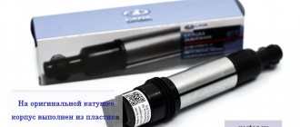
In this case, an equally important process will be the purchase of a high-quality ABS sensor. The fact is that each car uses certain sensor features that cannot work in tandem with other parts. If you have a car that was bought secondhand, it is better to determine which ABS sensors are currently installed. You will not always find original factory elements on the hubs. It is quite possible that the previous owner has already replaced the sensors with cheaper ones, which caused the breakdown of this element of the electrical system of your car. The selection of the sensor is of great importance for the normal operation of the machine. Watch a video about replacing the ABS sensor on a first generation Renault Logan:
Some nuances
Replacing sensors that are installed on the steering knuckles of the front wheels is much faster, since access to these parts is more convenient:
- The car is jacked up and the required wheel is removed.
- The bolts that secure the sensor are unscrewed, and the device is removed from the seat.
- The wiring fastening is released and the connector plug is disconnected.
- Installation of a new sensor is carried out in the reverse order.
Attention! When installing a new sensor, you must ensure that no dirt gets into the place where it fits.
Before replacing the sensor, reasons that could cause it to malfunction should be eliminated. Particular attention should be paid to specific problem areas found in each car model. For example, all FORD cars manufactured before 2005 suffer from interruptions in the operation of electrical equipment that occur as a result of frequent short circuits, and the pain point of the ABS system of these cars is the quality of wiring insulation. In this case, it will be possible to repair the sensor instead of completely replacing it.
How to recognize that the ABS sensor is no longer performing its functions
On older cars, a malfunction of the ABS sensor can lead to the most unpleasant consequences. If the wire breaks, the voltage may not reach the computer, just like when the wheel is locked. Therefore, a simple computer assumes this situation is that one of the wheels is blocked. Ultimately, Abs begins to unlock one wheel during braking, which can completely disable the braking system, and during a critical stop, provoke a complete loss of control right before the car turns over. Signs that the ABS sensor is faulty are:
- after inadequate operation of the system, the message “Abs” appears on the dashboard, the module stops working;
- on modern cars, after starting the engine, the ABS light does not go out, and the system stops working;
- during weak braking, the pedal vibrates, the brake force dispersal system is activated;
- auxiliary brake systems, amplifiers and balancing devices operate constantly;
- the on-board vehicle displays a number of problems that are related to the operation of the anti-lock braking system;
- When connected to a diagnostic computer, an error code for the anti-wheel lock system sensor is read.
Without the help of others, you can find a sensor malfunction if the ABS light is constantly displayed on the dashboard. This is the main indicator that a certain sensor has stopped working and the system simply does not work. In this case, the first task of the motorist will be to check the integrity of the wires to the sensors. These wires often break due to stones thrown into the hub area or other objects that cut the wire. Therefore, this problem is not uncommon; virtually all owners of cars with this module know it.
What to do in this case, how to measure the resistance
As can be seen from the breakdown options discussed above, most of the problems are related specifically to the ABS sensor. In this case, information about the malfunction immediately manifests itself in the form of a warning lamp glowing.
The question is how to check the ABS sensor without spending additional money and calling for service. All that is required to solve the problem is a combination device or multimeter, a car manual and wires with PIN connectors. If possible, use an assistant.
To check the resistance, switch the multimeter to ohmmeter mode, then proceed as follows:
- Use a lifting device (jack) to lift the machine.
- Remove the wheel if it restricts access to the sensor.
- Remove the screw that holds the device in place (it's easy to find at the back of the hub).
- Remove the housing that protects the control unit, and then remove the connectors through which power is supplied to the controllers.
- Insert wires with PIN connectors into the circuit, and then connect them with the sensor and multimeter.
- Measure the resistance and check the resulting parameter with what the car manufacturer recommends.
- Check the wires for continuity and short circuit.
Have a helper spin the wheel several times. At the same time, monitor and record resistance parameters. If the sensor is working properly, then during rotation the resistance indicator will change. The normal parameters are as follows (measurements are made in relation to the sensor):
- Leg device - 5-26 Ohm.
- Ground device - from 20 kOhm or more.
Anti-lock braking system malfunctions
All Priora ABS malfunctions can be divided into two categories. Malfunctions of the electronic part and malfunctions in the field of fluid mechanics. That's how they should be considered.
Electronic failures
This is a failure of electronics-related components:
- breaks in the electrical wiring harness;
- failure of rotation speed sensors;
- break or short circuit of the control valve activation coil;
- failure of the return pump electric motor;
- valve activation relay failure;
- program failure, or failure of the ABS control unit.
ABS malfunctions in the field of fluid mechanics
In this case, the most typical failures are leakage of oil seals in various connections and assemblies. Deterioration of working surfaces on disks, and as a result, a change in the distance between the sensor and the readable surface. System valves jamming. Clogging of hydraulic drive pipes and breakdown of the working part of the return pump.
Analysis of diagnostic results
The problem with the ABS function does not always lie in the sensors. The culprits of system failure may also be the wires connecting the elements to the control unit. That is why it is necessary to carry out 3 measurements and draw the following conclusions based on the results:
- If the resistance of the ABS sensor tends to zero or, conversely, the device shows an infinity symbol, then there is a malfunction of the element itself. Another option is a violation of the insulation or a break in the section of conductors from the connector to the sensor.
- The tester shows that the resistance is within normal limits, but when the brake disc rotates, its value remains constant. There are two versions here: severe contamination of the gear ring (as an option - destruction) and, again, failure of the sensor.
- The absence of voltage in the supply line indicates a break in the electrical circuit coming from the controller.
In the first case, it is necessary to remove the device from the hub and inspect the wires for fractures, breaks or short circuits. To be sure, measure the resistance again, while moving the conductors. If the result is negative, buy and install a new part.
If the resistance remains the same, get to the gear ring, clean it thoroughly and inspect it. If you find mechanical damage, it is better to replace the spare part.
Advice. Sometimes unscrupulous or ignorant auto mechanics damage the ring when repairing the suspension, or even throw it away completely. When picking up your car from a mechanic, always check that this important part is present.
In the case when there is no voltage in the controller circuit, you should ring this section of the wiring. How to do it:
- Find out where the electronic control unit for the hydraulic valves is located. For example, in a Chevrolet Aveo it is located behind the brake fluid reservoir, and in a Renault Megane it is located on the side of the alternator drive belt.
- Remove the block from the ECU and clean the contacts. Find the pinout of the wires or track them by color.
- Place a shorting jumper on the block located near the wheel. Test the circuit with an ohmmeter or a regular light bulb with a battery.
The easiest way to find the ECU if there is no documentation for the car is to follow the brake pipes leading to the hydraulic unit.
The latter stands next to the controller or is connected to it by a bundle of wires. If an open circuit is detected, you will have to look for the defect along the entire line in order to eliminate it. The work is quite complex, so it should be entrusted to an experienced auto electrician.
Is it possible to repair the sensor?
In the event of a malfunction, the device requires replacement (how to remove the ABS sensor was discussed above). Before starting work, contact your dealer and order a new part. After carrying out the work, test the device to ensure it is working properly. To do this, find a flat section of the road, accelerate the car to 30-40 kilometers per hour, and then sharply squeeze the brake.
If everything is done correctly, then impulses will be felt under your foot, and the car will stop. If the wiring is damaged, the latter must be replaced, and then diagnose the system using the algorithm already discussed.
Remember that if the sensor fails, it cannot be repaired. The only way out is replacement. What can be fixed is the wiring, which is changed or repaired with a soldering iron and electrical tape.
When connecting the wiring, be careful and take into account the polarity of the sensor. To avoid mistakes, look at the instructions, where the necessary symbols are indicated. Good luck on the roads and of course no breakdowns.
The serviceability of the anti-lock brake system is the basis for safe driving, especially in difficult road conditions. If, while driving a vehicle, the ABS system malfunction indicator lights up on the dashboard, you should immediately take measures to eliminate it.
Even if one of the ABS sensors does not work correctly, this leads to a complete failure of the anti-lock braking and traction control systems, and a malfunction of the exchange rate control system, if they are installed on the car.
Checking the quality of work performed
After replacing the sensor, its functionality is checked. To do this, it is enough to accelerate to a speed of 40 km/h on a flat, safe section of the road and perform sharp braking. If the car stops without pulling to the side, vibration is transmitted to the pedal and a specific sound of brake pads being activated is heard - the ABS system is operating normally.
Today you can easily find and buy any ABS sensors - from expensive original devices to analog parts at an affordable price. Remember that proper selection of system elements plays an important role in its uninterrupted operation. When choosing a sensor, study the manufacturer's instructions and make sure that it fits the car, and this review will help you replace the device yourself.
ABS control unit
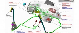
Location of brake system elements with ABS on a car
| 1 – brake system high pressure line pipe; 2 – brake pedal; 3 – main brake cylinder; 4 – additional tank; 5 – vacuum brake booster; 6 – hydraulic control unit (HCU); | 7 – front disc brake mechanism; 8 – caliper; 9 – rear drum brake mechanism; 10 – parking brake lever; 11 – parking brake cable. |
When the rotor teeth pass near the sensor, the magnetic field of the sensor changes, resulting in a voltage pulse being generated. This voltage is proportional to the wheel speed and can be measured. Speed sensor
The speed sensor detects the rotation of the wheel and consists of a permanent magnet and a coil. Front wheel sensors receive information from geared rotors located on the drive shafts.
ABS warning lamp: The ABS and EBD warning lamps are located in the instrument cluster.
1)
Lights up for 3 seconds after turning on the ignition and then goes out.
2)
Goes off when the engine starts.
3)
If the lamp is constantly on, it means there is a problem with the ABS.
4)
The lamp is on during self-diagnosis.
5)
If the warning light lights up periodically, it means there are problems with the ABS and the vehicle systems operate as if the vehicle does not have ABS and TCS systems.
6)
The lamp lights up when the electrical connector is disconnected from the control unit
ECU. EBD (Electronic Brake Force Distribution) warning light:
1)
Lights up after turning on the ignition.
2)
Goes off when the engine starts.
3)
Lights up when the parking brake lever is applied.
4)
Lights up when the brake fluid level is low.
5)
Lights up if the electronic brake force distribution EBD does not work: – if there is a malfunction in the solenoid valve; – if there is a malfunction in more than one sensor; – if the ECU control unit is faulty; – when the voltage is exceeded.
Hydraulic Control Unit (HCU)
The Hydraulic Control Unit (HCU) consists of an electric motor pump and a valve block to control the ABS pressure. The sensor is located in the pump motor and transmits an output signal to the ABS unit, which determines the performance of the pump.
Front brake fluid pipe hole diameter: 4.8 mm Rear brake fluid pipe hole diameter: 4.8 mm
A dual-circuit pump provides the required pressure, and a valve block distributes the pressure transmitted to the wheel brakes.
| A – front right inlet valve; B – rear left inlet valve; C – rear right inlet valve; D – front left inlet valve; E – front right exhaust valve; F – rear left exhaust valve; G – rear right exhaust valve; H – front left exhaust valve; M – + engine; N – motor (GND). |
ABS self-diagnosis
The ABS control unit begins to perform self-diagnostic functions after turning on the ignition. The ABS control module detects faults for each circuit and component by comparing the system condition to a limited set of conditions in the ABS control module. The ABS control unit stores the fault code and then displays it to the scan tool as four-digit codes.
Checking Self-Diagnostic Codes
| EXECUTION ORDER |
| 1. Turn the ignition key to the OFF position and connect the scan tool to the scan connector located near the vacuum booster in the engine compartment. |
| 2. Turn the ignition key to the ON position and set the vehicle model and diagnostic tool model on the device. |
| 3. Select the parameter to be tested after the block is initialized. |
| 4. Press check codes #1 and find out if a fault is recorded. |
| Warning The fault code is a four-digit number that appears continuously until the fault code is cleared by the diagnostic tool. |
| 5. Using the list of fault codes, identify the faulty element and restore its functionality. |
| 6. After erasing the fault codes from the memory of the ABS control unit, select inspection point No. 4. |