FakeHeader
Comments 65
I have the same ones, I leave them on the sidelights, they all say that the headlights weren’t turned off, the battery is good, right?))))
Same crap.” that the Acoma is good? Exactly.
They look beautiful. In my photo the dimensions actually look bluish =)
Think about it, they don’t fit in mine, I also bought one of these)))) I put one of them in the interior for additional lighting and in the glove compartment, now it’s as bright as day)))))
It turned out great, just describe the process in more detail? I plan too, but there is no diagram anywhere. Tell me please?
what the hell is the process, I took out a regular light bulb from the dimensions, installed a diode, that’s it! 1 minute business.
very useful information, probably no one knew how to change a light bulb on a Lada. Also show me how to replace the air filter.
I've met dudes who can't even install a spare tire (they don't know how).
It's like the neighbor is on)))
They look really cool! They'll just burn out soon. ... You need to immediately install a voltage stabilizer on them. Look on Ali or eBay. It's worth a penny.
They won’t burn out, I’ve been driving for a long time and there are no problems.
And I have a month and a month for a replacement, a month and a replacement. Here I connected the DRL through a stabilizer.
what kind of stabilizer is this? show me a link at least
It’s a hat for me) The yellow ones look somehow more menacing or something))))
You are a MEEEEEGAATUNER! Well done Ida!
When will such vehicles be banned? It seems like 25 years already, but it feels like 16.
I agree, I don’t even know what to say...
A guy found something like Instagram for himself
Advertisements on NN.RU – Auto
With us you can not only extend the frame to fit a body of 5.1 m, 6.2 m, 7.5 m, 9 m for Maz Zubrenok, Maz, Kamaz, Ural, Zil, Mitsubishi, Nissan.
Wide selection of hydraulic pumps and hydraulic motors of all series. Axial piston hydraulic motor. Splined shaft, reverse rotation. Analogs - (many. Price: 1,000 rub.
We sell KAMAZ injection pump (All types) BOSCH injection pump for KAMAZ 1 year warranty Bosch Euro-3 injection pump 1 0402698817 (electr.) EURO-3 – 134,200 rub. 2. Price: 131,000 rub.
A certified truck conversion organization invites you to: lengthen, re-extend and convert, p.
Sooner or later, most car owners are faced with the fact that the interior lighting stops working. Let's look at the reasons for this malfunction and figure out what to do in this or that case.
To understand where to look for the cause of a breakdown, you need to understand how the interior lighting system generally works. Here is a typical simplified diagram. It may include many more different devices, but the cars are different and it is impossible to draw a diagram for each specific instance. In most cases, the interior light is connected like this:
Now let’s go over the reasons that can cause interior lighting to fail.
Reason #1: Burnt out light bulb
It’s very simple and elementary, but some car owners start looking for a “fault” in the depths of the electrical system. No need - just check the lamp. You can just look at the thread, or you can ring it with a tester. The latter option will help you identify a burnt-out light bulb much more accurately - sometimes it is not the spiral that burns out, but the contact inside the base, and everything looks quite good in appearance.
Reason #2: Blown fuse
The second reason why the interior light may not work is a blown fuse. Almost always, interior lighting “shares” a fuse with other devices. Therefore, if, along with the light, a clock or radio tape recorder, for example, stopped working, then the likelihood of a blown fuse is extremely high.
Find the correct fuse in the appropriate block and make sure it is intact. If the fuse does blow, there is probably a reason for this - a short circuit. Therefore, it is not a fact that after inserting a new fuse everything will work. It is quite possible that it will burn out immediately. If this happens, there is definitely a short circuit. Need to know how to find a short circuit in a car
At the same time, a fuse does not always blow due to a short circuit. Its jumper may simply be old (tired) or made of poor quality material.
Reason #3: Oxidized contact
There are plenty of contacts in the interior lighting circuits. But the contacts inside the lampshade and door limit switches are most susceptible to oxidation. Limit switches very often oxidize in many Russian cars, since they do not have a rubber casing.
It is very easy to identify an oxidized contact - just look at it. Remove the lampshade, disassemble it and make sure the contacts are clean. If there is oxide, clean it with a small flathead screwdriver or fine sandpaper. Do the same with the limit switches - each such switch must be removed and inspected. Before removing the limit switches, it is better to disconnect the battery, because very often during removal the positive wire of the switch shorts to the body.
Reason #4: Broken wire
The reason why the light in the cabin does not work may be a broken wire. Wires that are forced to bend due to their location are especially susceptible to damage. So, the wires running into the trunk lid or doors often break. This occurs due to frequent twisting or bending of the wire when opening these body elements. In theory, the interior lighting wiring does not go into the doors or trunk, but the general meaning is the same - the wire can be broken, crushed or broken.
Restoring the backlight and changing the warning lamps
We remove the light bulb that needs to be replaced (the purpose of the light bulbs is in the first photo of the article). To do this, turn the socket counterclockwise 90 degrees, and it will easily come out along with the light bulb.
Replacing a light bulb without disconnecting the power wires on a VAZ 2110
We remove the burnt device from the socket, insert a new one in its place and install the socket with the lamp in place, turning it 90 degrees, but clockwise. After this, we install the terminal on the battery, turn on the ignition and check the operation of the VAZ panel, performing the appropriate manipulations: turn on the hand parking brake, headlights, turn indicators, high beam headlights, etc. If everything is in order, then install the panel and decorative trim in place .
I replaced the lamps, but there is still no backlight - possible reasons
It may happen that the lighting or indication on the VAZ will not be restored even after replacing the lamps. What is the problem and how to find and fix it? Let's look at the main reasons for this situation, and the easiest way to search is in the order in which they are listed:
- The power and control cable connectors have oxidized.
- The contact pads of one or a group of lamps have oxidized.
- The fuse that powers the backlight bulbs has blown.
- The conductive paths have oxidized and become short-circuited or “burnt out.”
- The wires supplying certain lamps are short-circuited to the car body.
So, let's start the search. We check the quality of the contacts on the connectors through which the control cables are connected to the VAZ instrument panel. The contacts (they are in plastic blocks) should not be oxidized, and the connectors themselves should fit tightly in their sockets. Additionally, it makes sense to tug with a little force (without fanaticism!) each wire in the bundles: it can simply break inside from vibration and hang on the same insulation.
Checking the quality of contact pads is quite simple visually. It is necessary to remove the non-working lamps and examine these areas in bright light. If they are covered with plaque (usually white or greenish), it needs to be removed, for example, with a rubber band.
We open the fuse panel of the dozens and find the fuse responsible for powering the backlight. It should fit tightly in its socket, and the contacts should not be oxidized. At the same time, we check the serviceability of the fuse - it could have burned out from a power surge or simply been defective.
In order to check the conductive paths on the board, you will have to definitely remove the protective casing from the VAZ panel. We unscrew 10 screws and carefully inspect the tracks. They should not be oxidized or covered with a white coating. Remove plaque with the same eraser. If we find a burnt or rotted track, we restore contact using a soldering iron and a piece of tinned wire.
In this case, as a rule, the fuse burns out or the wire burns out at the point of the short circuit. We replace the fuse with a new one with the same rating. If it burns out again, then the problem is a short circuit: you will have to find it by walking along the harness. This can be quite a difficult task since the harness is located under the dashboard. But nevertheless, it must be performed in order to find and eliminate the short circuit.
If the fuse does not blow and the lamp still does not light, then in the same manner it makes sense to look for the burnt out wire.
If you carefully read this article, you can easily replace the backlight and display lamps on the VAZ 2110 dashboard on your own, and, if necessary, find and fix the problem without the help of a specialist.
Previous Replacing car lampsHow to replace a license plate lamp on a Lada Priora Next Replacing car lampsReplacing a low beam lamp on a Renault Megane 2
How to replace dashboard lamps?
Well, firstly, before carrying out any electrical work in the car, it is necessary to turn off the power to the vehicle’s on-board network. To do this, open the hood and remove the negative terminal of the battery.
How to change light bulbs on a VAZ 2107
Inside the car, use a flat-head screwdriver to pry and pull out the plastic handles on the heater air damper control drive. After this, unscrew the nut located on the small handle designed to reset the daily mileage. Then remove the washer from it and push the handle deep into the instrument panel.
- Using the same screwdriver, pry off the plastic plug, which is located on the far right side of the panel in the lower corner. Under this plug there is a panel fastening bolt, which also needs to be unscrewed using a Phillips screwdriver.
- Pull the heater drive control button towards you and remove it from the plug. After this, push the connector deep into the dashboard. The panel must be pulled out starting from the right side. During the dismantling process, unscrew the nut securing the speedometer drive cable, then pull it out and leave it hanging. Remove the vacuum supply hose from the fitting located on the econometer. Finally, pull out all the wire connectors and remove the instrument panel from the dashboard.
- In total, there are about 9 backlight lamps on the instrument panel. Each of them is removed by pressing and turning the cartridge 90 degrees. After this, the old lamp is pulled out, and a new one is installed in its place directly into the socket.
VAZ 2110 (new model) - changing the backlight with your own hands
- First of all, you need to unscrew the two screws that secure the decorative trim at the top. This trim is installed directly on the dashboard.
- Pull out the knob for adjusting the backlight and use pliers to unscrew the large nut located under it. After the nut is removed, make sure that the regulator does not go under the panel, since it will be difficult to get it out later.
- In the left corner, near the button for turning on the fog lights, pull out another plug. There is a screw under it that also needs to be unscrewed. After this, pull the decorative trim towards you. As soon as the button connectors appear, disconnect them and pull the cover even further.
- Inside the panel, find two screws that secure the instrument panel from the inside. Unscrew them and pull the instrument panel out. During the removal process, pull out the plug connector from the rear of the instrument panel.
- The lamp sockets are unscrewed by turning them 45-90 degrees. Then the burnt out lamps are unscrewed from the socket. After this, new lamps are installed in place of the old ones, and the dashboard is assembled in the reverse order.
How to remove lamps on Lada Priora
- To make it easier, take a Phillips screwdriver. Unscrew the two screws located in the upper inner part of the instrument panel.
- There is a small plastic panel (or trim) located under the steering column. At the top of the panel, unfasten the latches, and at the bottom, turn three fasteners made of plastic. After the trim is removed, you will see two more screws securing the instrument panel. They also need to be unscrewed.
- Now lower the steering wheel down, but do not remove it. Pull the decorative trim towards you. If it does not give in, you can carefully pry it off with a flat screwdriver without damaging the plastic coating. Inside the torpedo you can find two more screws. The instrument panel itself rests on them. Unscrew them, holding them with your hand, so as not to lose washers and screws, which can easily fall inside the torpedo.
- Pull the instrument panel towards you so that the wiring block is visible. Unplug the plug from the connector and place it outside so that it does not go inside. Expand the instrument panel and find the lamp sockets.
- As in other cars, the cartridge is pulled out by turning. You can change the lamps as a whole with a socket or separately. Currently, prices allow replacing lamps along with sockets. This will be much more rational than sitting and waiting for the cartridge to fail.
- After replacing the lamps, reassemble the panel in the reverse order.
At the end, forget to connect the battery terminal. This completes the replacement of the dashboard lamps.
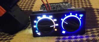
Replacing the standard clock of a VAZ 2107 with digital ones
The standard clock is not informative enough, and it looks too standard. Therefore, many owners of the “Seven” change them to more advanced models. Usually this is an electronic watch with a voltmeter function. Such a device not only looks more modern and attractive, but also allows you to control the voltage of the on-board network. Installing an electronic clock on a VAZ 2107 is easy. On the market you can find a wide range of electronic watches for the “seven” with different display colors and functionality.
A good option is a watch with alarm, calendar, voltmeter and thermometer functions. The most advanced model has two temperature sensors - internal and external, which allows you to control two temperature parameters at once.
Such clocks fit perfectly into the place of the standard ones, and connecting them does not require the installation of additional power circuits. The only thing you should take care of is to install an external temperature sensor and run a wire from it to the location where the clock is installed.
If the electronic clock does not have a function for measuring external temperature, its installation is completely similar to the installation of a standard clock and does not require additional actions.
We make a unique design with our own hands
Everything is much more complicated here, but you can save money. In this case, no sets are purchased. Everything is created independently and exclusively to your taste. True, you can first look at photographs of ready-made solutions. They will help you move in the right direction.
This option is preferable not only because of saving money. You can create something truly individual and unique. First, you should replace the arrows and stickers. Here you can again go to the store or create something of your own. You can also order arrows and stickers from a studio specializing in tuning. It will cost you a little more, but the effect will be much stronger.
What to do if the battery is boiling
You can conclude that the VAZ-2107 battery is “boiling” if the following problems occur:
- the corresponding indicator stops lighting;
- the voltmeter behaves inappropriately, and its needle goes to the right;
- A characteristic odor appears in the car interior.
“Boiling” of the battery is caused by problems with the voltage stabilizer. It is strictly forbidden to continue driving the car in such a situation: this can lead to breakdowns of all electrical equipment in the car. In order to get to the service center with safety for yourself and the car, you should forcefully turn off the generator set.
This can be done by physically removing the wire from the terminal with the abbreviation “61” located on the generator itself. The car will continue to move solely using the accumulated charge.
VAZ 2107 on-board network systems and the principle of their operation
Considering that the “sevens” were produced with both carburetor and injection engines, their electrical circuits are different.
The electrical circuit in the carburetor VAZ 2107 is somewhat simpler than in the injection ones
The difference between them is that the latter have an on-board network supplemented with an electronic control unit, an electric fuel pump, injectors, and sensors for the engine control system.
The injection VAZ 2107 circuit includes an ECU, an electric fuel pump, injectors and control system sensors
Regardless of this, all electrical equipment of the “seven” can be divided into several systems:
- car energy supply;
- starting the power plant;
- ignition;
- external, internal lighting and light signaling;
- sound alarm;
- additional equipment;
- engine control (in injection versions).
Let's look at what these systems consist of and how they function.
Energy supply system
The VAZ 2107 energy supply system includes only three elements: a battery, a generator and a voltage regulator. The battery serves to provide electricity to the vehicle's on-board network when the engine is turned off, as well as to start the power plant by supplying power to the starter. The “sevens” use lead-acid starter batteries of type 6ST-55 with a voltage of 12 V and a capacity of 55 Ah. Their characteristics are quite sufficient to ensure the start of both carburetor and injection engines.
VAZ 2107 was equipped with 6ST-55 batteries
A car generator is designed to provide electric current to the vehicle's on-board network, as well as charge the battery when the power unit is running. Until 1988, “Sevens” were equipped with generators of the G-222 type. Later, VAZ 2107 began to be equipped with current sources of type 37.3701, which had successfully proven themselves on the VAZ 2108. Essentially, they have the same design, but differ in the characteristics of the windings.
The generator generates current to provide electricity to the vehicle's on-board network
Generator 37.3701 is a three-phase electromechanical alternating current device with electromagnetic excitation. Taking into account the fact that the on-board network of the “seven” is designed for direct current, a rectifier is built into the generator, which is based on a six-diode bridge.
The generator is installed on the power plant of the machine. It is driven by a V-belt from the crankshaft pulley. The amount of voltage generated by the device depends on the number of crankshaft revolutions. To ensure that it does not go beyond the limits established for the on-board network (11.0–14.7 V), a microelectronic voltage regulator of the Ya112V type works in tandem with the generator. This is a non-separable and non-regulated element that automatically and continuously smoothes out voltage surges and dips, maintaining it at a level of 13.6–14.7 V.
The basis of the power supply system is a battery, a generator and a voltage regulator
The generator begins to produce current when we turn the ignition key to position “II”. At this moment, the ignition relay is turned on, and voltage from the battery is supplied to the exciting winding of the rotor. In this case, an electromotive force is generated in the generator stator, inducing an alternating current. Passing through the rectifier, alternating current is converted to direct current. In this form, it goes to the voltage regulator, and from there to the on-board network.
Also check out the electrical diagram of the VAZ 21074: https://bumper.guru/klassicheskie-modeli-vaz/elektrooborudovanie/vaz-21074-inzhektor-shema-elektrooborudovaniya-neispravnosti.html
Video: how to find a generator malfunction
Power plant starting system
The VAZ 2107 engine starting system includes:
- battery;
- starter with relay;
- ignition switch (lock).
1 - starter; 2 - relay; 3 — ignition switch; 4 - battery
As a device for starting the power unit in the VAZ 2107, a four-brush DC electric starter of the ST-221 type is used. Its circuit does not have protection in the form of a fuse, but it provides two relays: an auxiliary (power supply) and a retractor, which ensures the coupling of the device shaft with the flywheel. The first relay (type 113.3747–10) is located on the engine panel of the machine. The solenoid relay is mounted directly on the starter housing.
The ST-221 starter is installed in the VAZ 2107
The engine start is controlled using the ignition switch located on the steering block. It has four positions, by moving the key to which we have the opportunity to turn on the circuits of various electrical equipment:
- “0” – a position in which all electrical devices are turned off, with the exception of the sound signal, cigarette lighter, interior lamp, and sometimes the radio (depending on how it is connected);
- “III” – exterior headlight lamps, windshield washer and wipers are powered;
- “I” – power is supplied to the ignition system, to the instrument panel, warning lamps and heater fan;
- “II” – current is supplied to the starter relay, retractor and starter field windings.
The engine starts as follows. When the key is turned to position “II,” the corresponding contacts of the ignition switch are closed, and current flows to the terminals of the auxiliary relay, starting the electromagnet. When its contacts also close, power is supplied to the windings of the retractor. At the same time, voltage goes to the starter. When the retractor relay is activated, the rotating shaft of the starting device engages with the flywheel crown and through it transmits torque to the crankshaft.
Using the lock, various circuits of the machine's on-board network are switched on
When we release the ignition key, it independently returns from position “II” to position “I”, and the current stops supplying the auxiliary relay. This opens the starter circuit and turns it off.
Video: if the starter does not turn
Ignition system
The ignition system is designed for timely ignition of the combustible mixture in the combustion chambers of the power plant. Until 1989 inclusive, the VAZ 2107 was equipped with a contact type ignition. Its design was:
- a coil representing a voltage-increasing transformer;
- distributor with contact breaker;
- high voltage wires;
- candles.
1 - generator; 2 — ignition switch; 3 - distributor; 4 - breaker; 5 — candles; 6 - coil; 7 - battery
The ignition coil is used to increase the voltage coming from the battery. The classic (contact) ignition system used a two-winding coil type B-117A, and the contactless one used 27.3705. Structurally they are no different. The difference between them lies only in the characteristics of the windings.
Video: repair of the ignition system of the VAZ 2107 (part 1)
The distributor is necessary to interrupt the current and distribute voltage pulses across the spark plugs. In the "sevens" distributors of type 30.3706 and 30.3706–01 were installed.
By means of high-voltage wires, high-voltage current is transmitted from the contacts of the distributor cap to the spark plugs. The main requirement for wires is the integrity of the conductor and insulation.
Spark plugs produce a spark at their electrodes. The quality and time of the fuel combustion process directly depends on its size and power. From the factory, VAZ 2107 engines were equipped with spark plugs of type A-17 DV, A-17 DVR or FE-65PR with an interelectrode gap of 0.7–0.8 mm.
The contact ignition system worked as follows. When the ignition was turned on, the voltage from the battery went to the coil, where it increased several thousand times and followed the contacts of the breaker located in the ignition distributor housing. Due to the rotation of the eccentric on the distributor shaft, the contacts closed and opened, creating voltage pulses. In this form, the current entered the distributor slider, which “carried” it across the contacts of the cover. These contacts were connected to the central electrodes of the spark plugs via high voltage wires. This is the path the voltage passed from the battery to the spark plugs.
After 1989, the “Seven” began to be equipped with a contactless ignition system. This was due to the fact that the breaker contacts constantly burned and became unusable after five to eight thousand kilometers. In addition, drivers often had to adjust the size of the gap between them, as it constantly got lost.
The contactless ignition system uses a switch instead of a breaker
The new ignition system no longer had any distributor. Instead, a Hall sensor and an electronic switch appeared in the circuit. The operating principle of the system has changed. The sensor read the number of revolutions of the crankshaft and transmitted an electronic signal to the commutator, which, in turn, generated a low voltage pulse and sent it to the coil. There, the voltage was increased and supplied to the distributor cap, and from there, according to the old scheme, it was supplied to the spark plugs.
Video: repair of the ignition system of the VAZ 2107 (part 2)
In the injection-powered "sevens" everything is much more modern. Here in the ignition system there are no mechanical components at all, and the role of the ignition coil is played by a special module. The operation of the module is controlled by an electronic unit, which receives information from several sensors and, based on it, generates an electrical impulse. Then it transmits it to the module, where the pulse voltage increases and is transmitted through high-voltage wires to the spark plugs.
In injection VAZ 2107, the electrical impulse is generated by the ECU
System of external, internal lighting and light signaling
The vehicle lighting and alarm system is designed to illuminate the interior of the cabin, the road surface in the front and rear of the car in the dark or in conditions of limited visibility, as well as warn other road users about the direction of the maneuver by giving light signals. The system design includes:
- front block headlights;
- turn signal indicators (side indicators);
- rear lights;
- salon lamp.
The lighting system includes front and rear headlights, turn signal indicators, and interior lamp
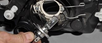
VAZ 2107 was equipped with two front block headlights, each of which combined high and low beam headlights, side lights and direction indicators in its design. Far and near lighting in them is provided by one double-filament halogen lamp type AG-60/55, the operation of which is controlled by a switch located on the steering column on the left. The turn signal unit contains a lamp of type A12–21. It turns on when you move the same switch up or down. The side light is provided by A12-4 type lamps. They light up when you press the exterior lighting switch. The turn signal also uses A12-4 lamps.
The rear lights of the “seven” are divided into four sections:
- direction indicator (lamp A12–21–3);
- side light (A12–4);
- fog light (A12–21–3);
- reversing lights (A12–21–3).
The rear fog lights light up when you press the button to turn them on, which is located on the center console of the car. The reversing headlights turn on automatically when you engage reverse gear. A special “frog” switch installed in the rear of the gearbox is responsible for their operation.
The interior of the car is illuminated using a special lamp located on the ceiling. Its lamp turns on when the side lights are turned on. In addition, its connection diagram includes door limit switches. Thus, the lamp starts to glow when the side lights are turned on and at least one of the doors is open.
The lampshade is designated number 64
Sound alarm system
The sound alarm system is designed to provide a sound signal to other road users. Its design is very simple, and consists of two electric sound signals (one high-pitched, the other low), relay R-3, fuse F-7 and a power button. The sound alarm system is constantly connected to the on-board network, so it works even when the key is pulled out of the ignition switch. It is turned on by pressing a button located on the steering wheel.
1 - high and low tone signals; 2 — mounting block; 3 - power button
The sound sources in the “sevens” are signals like 906.3747–30. Each of them has a trim screw to adjust the tone. The design of the signals is non-separable, therefore, if they fail, they must be replaced.
Video: repair of the VAZ 2107 sound signal
Additional electrical equipment for VAZ 2107
Additional electrical equipment of the “seven” include:
- electric motors of the windshield wiper gear motor;
- windshield washer pump electric motor;
- cigarette lighter;
- heater fan motor;
- radiator cooling fan electric motor;
- watch.
Windshield wiper motors drive a trapezoid, which in turn moves the windshield wipers across the car's windshield. They are installed in the rear of the engine compartment, immediately behind the engine shield of the car. The VAZ 2107 uses gearmotors of type 2103–3730000. Power is supplied to the circuit when the right steering column switch is moved.
The washer motor drives the washer pump, which supplies water to the washer line. In the "sevens" the motor is part of the design of the pump built into the tank lid. Part number 2121–5208009. The washer motor is activated by pressing the right steering wheel switch (towards you).
1 — electric motors of the windshield wiper; 2 — washer motor; 3 — mounting block; 4 — ignition switch; 5 - washer switch
The cigarette lighter, first of all, is not used to allow the driver to light a cigarette from it, but to connect external electrical equipment: a compressor, navigator, DVR, etc.
The cigarette lighter connection diagram consists of only two elements: the device itself and fuse F-6. Switching on is carried out by pressing the button located at the top of it.
The cigarette lighter is connected to the on-board network via a fuse without a relay
The heater fan electric motor is used to force air into the vehicle interior. It is installed inside the heating unit. The device catalog number is 2101–8101080. The electric motor can operate in two speed modes. The fan is turned on with a three-position button located on the dashboard.
The electric motor of the radiator cooling fan is used for forced air flow of the main heat exchanger of the vehicle when the coolant temperature exceeds the permissible values. Its connection diagrams for carburetor and injection “sevens” are different. In the first case, it is turned on by a signal from a sensor installed in the radiator. When the coolant is heated to a certain temperature, its contacts close and voltage begins to flow into the circuit. The circuit is protected by relay R-4 and fuse F-7.
1 — fan electric motor; 2 - sensor; 3 — mounting block; 4 - ignition relay; 5 - ignition switch
In the injection VAZ 2107, the scheme is different. Here the sensor is installed not in the radiator, but in the cooling system pipe. Moreover, it does not close the fan contacts, but simply transmits data on the refrigerant temperature to the electronic control unit. The ECU uses this data to calculate most commands related to engine operation, incl. and to turn on the radiator fan motor.
In injection "sevens" the electric radiator fan is turned on by a signal from the ECU
The clock is installed inside the car on the dashboard. Their role is to show the time correctly. They have an electromechanical design and are powered by the machine's on-board network.
The clock is constantly connected to the on-board network
Engine management system
Only injection power units are equipped with a control system. Its main tasks are collecting information about the operating modes of various systems, mechanisms and engine components, processing them, generating and sending appropriate commands to control devices. The system design includes an electronic unit, injectors and a number of sensors.
The ECU is a kind of computer in which a program is installed to control the operation of the engine. It has two types of memory: permanent and operational. The computer program and engine parameters are stored in permanent memory. The ECU controls the operation of the power unit, checking the serviceability of all components of the system. If a breakdown is detected, it switches the engine to emergency mode and gives a signal to the driver by turning on the “CHEK” lamp on the instrument panel. The RAM contains current data received from sensors.
The injectors are designed to supply gasoline to the intake manifold under pressure. They spray it and inject it into the receiver, where a flammable mixture is formed. At the heart of the design of each of the nozzles is an electromagnet that opens and closes the nozzle of the device. The operation of the electromagnet is controlled by the ECU. It sends electrical impulses at a specific frequency, causing the electromagnet to turn on and off.
The control system includes the following sensors:
- Throttle position sensor. It determines the position of the damper relative to its axis. Structurally, the device is a variable resistor that changes resistance depending on the angle of rotation of the damper.
- Speed sensor. This element of the system is installed in the speedometer drive housing. A speedometer cable is connected to it, from which it receives information and transmits it to the electronic unit. The ECU calculates the speed of the car based on its impulses.
- Refrigerant temperature sensor. As already mentioned, this device serves to determine the degree of heating of the refrigerant that circulates in the cooling system.
- Crankshaft position sensor. It generates signals about the position of the shaft at a certain point in time. This data is necessary for the computer to synchronize its operation with the cycles of the power plant. The device is installed in the camshaft drive cover.
- Oxygen concentration sensor. Serves to determine the amount of oxygen in exhaust gases. Based on this information, the ECU calculates the proportions of fuel and air to form the optimal combustible mixture. It is installed in the intake area immediately behind the exhaust manifold.
- Mass air flow sensor.
This device is designed to calculate the volume of air entering the intake manifold. The ECU also needs such data to correctly form the fuel-air mixture. The device is built into the air duct. The operation of all systems and mechanisms is controlled by the ECU
Information sensors
The information sensors of the VAZ 2107 include an emergency oil pressure sensor and a fuel level indicator. These devices are not part of the engine management system, since the engine can work well without them.
The emergency oil pressure sensor is designed to determine the pressure in the lubrication system and promptly notify the driver when it drops to critical levels. It is installed in the engine cylinder block and connected to a warning lamp located on the instrument panel.
The fuel level sensor (FLS) is used to determine the volume of fuel in the tank, as well as warn the driver that it is running low. The sensor is installed in the gas tank itself. It is a variable resistor, the slider of which is attached to the float. The fuel level sensor is connected to a gauge located on the instrument panel and a warning lamp located there.
Sensors are connected to instruments and warning lamps
Connection diagram and fuse location
It is rare, but it happens that replacing a light bulb does not lead to the desired result: the lamp still does not light or one of the modes does not work (does not work correctly). There are few problems that caused the malfunction, and almost all of them can be eliminated on your own. First, let's take a look at the electrical diagram for connecting the interior lamp to the on-board network.
The scheme is quite simple. Positive polarity voltage is supplied to the lamp through a fuse in the mounting block and is constantly present on the lamp. In the left position according to the diagram of the switch built into the lampshade, the second terminal of the lamp is shorted to the body (minus power), and the lamp is constantly on.
If you move the switch to the position indicated in the diagram, then the second output of the lamp is connected to the limit switches located in the pillars of all four doors. These limit switches are connected in parallel, and the second terminal of each of them is connected to the body. When any of the doors is opened, the corresponding limit switch is triggered and connects the lamp to the body - the light in the cabin lights up.
Now a few words about the fuse that powers the interior lighting. It is located in the mounting block, which in turn is located under the dashboard to the left of the driver.
Fuse box location
Fuse F17 with a rating of 7.5 A is responsible for interior lighting. You can see its location in the photo below.
So we learned how to independently change the light bulbs in the interior lamps of a VAZ 2110 car. The matter is so simple that it is pointless to contact a specialist because of such a trifle.
Previous Interior lighting The interior lighting of the VAZ 2107 does not work - how to change the bulbs and which ones are needed Next Interior lighting Why the interior lighting does not work on the VAZ 2114 - how to change the lamp?
Thank you, it helped! It didn’t help
All instruments and sensors on the instrument panel have failed
After purchasing my VAZ 2106, literally a couple of days later, the following trouble awaited me.
When the ignition was turned on, neither the emergency oil pressure light nor the battery charging came on, and the gasoline level sensor did not work.
At first I thought that the battery terminal had simply come loose, but then I checked and everything turned out to be normal. Just in case, I decided to turn the starter, and as it turned out, everything worked, it turned and the car started up normally.
But even after this, none of the instruments and sensors worked; by the way, the tachometer also stood still and the needle did not budge. This was the picture with the ignition on and even the engine running, all the instruments froze tightly:
I decided to check all the fuses, since I simply could not see any other reason for what was happening. Since the location of the fuses in the mounting block of the VAZ 2106 was not familiar to me, I decided to check everything at random. I took the fuses out of the block one by one and inspected them.
It was already quite dark, and not at first glance all the veins on each fuse were intact. In the morning I checked everything again and saw that on one side, barely noticeable, the wire had burned out. The photo below shows the fuse that is responsible for the functionality of the sensors and devices of the VAZ 2106.
After I replaced it with a working one, all the sensors and arrows started working and everything fell into place.
So, if someone has a similar problem, or this is your first time encountering this, keep in mind that the fuse, which is shown in the middle photo in this article, is to blame. I hope that my experience will be at least useful to someone.
How to disassemble the lampshade and replace the lamp
In this section we will find out how to remove the lampshade of the Lada Priora “Norma” and replace the lamp. To work, we will need a small flat-head screwdriver and, of course, a new C5W lamp.
We insert a screwdriver under the passenger side glass and push it down, overcoming the force of the spring latch. We fold the glass down and remove the latches on the driver's side from engagement with the lamp.
Removing glass from the interior lighting of the Lada Priora “Norma”
In front of us is a light bulb, clamped with spring contacts. We simply pull it out and install a new one in place of the burnt one.
Replacing the interior light bulb of Lada Priora “Norma”
As for repairing lamps on the Lada Priora “Lux”, we will not do this, since replacing LEDs will require not only knowledge of radio engineering, but also the ability to hold a soldering iron. If you have such knowledge, then you can watch a video about replacing LEDs in the Lux rear light.
Replacing the LED in the rear interior lighting lamp of Lada Priora “Lux”
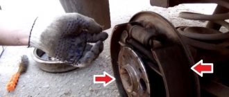
Design and characteristic malfunctions of the rear lights of the VAZ-2107
Structurally, the rear light of the VAZ-2107 car consists of:
- left and right diffusers;
- left and right conductors;
- two 4 W lamps and two sockets for them;
- six lamps with a power of 21 W and six sockets for them;
- four M5 nuts.
The rear light of the VAZ-2107 consists of diffusers, conductors, lamps and sockets
The brake light and side lights on the rear light should be red, the turn signal should be orange, and the reverse light should be white. The most typical malfunctions of the rear lights of the VAZ-2107:
- lack of mass on the lantern;
- lamp burnout;
- oxidation of contacts;
- broken or frayed wiring;
- failure of connector contacts, etc.
No mass
One of the reasons that the tail light does not work may be the lack of weight on it. You can check the integrity of the ground wire visually or by ringing it with a tester. The ground wire in the standard configuration of the VAZ-2107 is usually black, and it occupies the extreme position on the connector block. It is followed by wires:
- brake light (red);
- side lights (brown);
- fog lamps (orange-black);
- reverse lamps (green);
- direction indicator (black and blue).
The wires on the connector go in a certain sequence and have their own colors
Lamp burned out
The most common malfunction of rear lights is the burnout of one of the lamps. In this case you will need:
- Remove the plastic plug from the trunk side, which is secured with four plastic screws;
The plastic plug for the rear light of the VAZ-2107 is secured with four plastic screws
- Using a 10mm wrench, unscrew the 4 nuts on which the flashlight is attached;
The nuts securing the rear light of the VAZ-2107 are unscrewed with a 10mm wrench
- Disconnect the power connector;
To remove the flashlight and replace the lamps, you must disconnect the power connector
- Remove the headlight and replace the burnt out lamp.
The reversing lights of the VAZ-2107 use lamps with a power of 4 W and 21 W
Contacts have oxidized
Oxidation or clogging of the contacts of the connector block may be a consequence of their insufficiently tight connection, as well as dust and other small mechanical particles getting inside the headlamp due to wear or drying out of the rubber seal. The processes of oxidation and contamination of contacts can be prevented through regular preventive inspections and maintenance of all elements of the lighting system.
Broken wiring
The integrity of the wiring is checked with a multimeter if the location of the break cannot be determined visually. The purpose of each of the wires coming to the connector can be determined from the VAZ-2107 electrical equipment connection diagram.
Failure of connector contacts
Deterioration of contact in the detachable connection between the board and the plug can lead to burnout of the track with the impossibility of restoration. In this case, additional wires are soldered between the connector and the socket or the connector is completely replaced. It should be remembered that the new board may be equipped with a cartridge with non-spring metal, so it makes sense to keep the old cartridge. When replacing the board, it should be taken into account that the color of the wires may not match the color on the original blocks, so it is better to focus on the order of the contacts and solder the wires of the new connector to the wires in the harness sequentially one at a time.
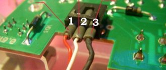
Connection diagram
On the board connector, the tracks leading to the sockets of different lamps are marked with numbers:
- 1 - mass;
- 2 - brake light;
- 3 — side lights;
- 4 — fog lights;
- 5 — reversing lamp;
- 6 — direction indicator.
The paths leading to the sockets of different lamps are marked with certain numbers
Tail lights
We move to the rear of the car. There are screws on the trunk side that secure the protective cover.
- Unscrew them and remove the plastic cover of the lights
- Remove the power plug and loosen the plastic board holders with your fingers. To replace it, just loosen the board latches to remove it from the flashlight body
- We remove it from the taillight unit
All lamps are located on the printed circuit board. To replace them, you need to turn them a quarter turn and pull them out of the socket. We replace burned out ones. We assemble the lantern in reverse order.
Video, replacing rear light bulbs on a Zhiguli 2105-07:
https://vk.com/video_ext.php
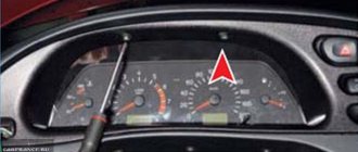
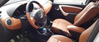
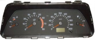
Interior of the VAZ-2107: briefly about the purpose of the instrument panel elements
There is a speedometer on the panel board on the right side, which informs the driver about the speed of movement. The scale provides a gradation from 0 to 180 kilometers per hour. In addition, this device has two dials that duplicate the mileage traveled by the car. The upper pointer can be adjusted, but the lower analogue does not have such a function.
The tachometer in the VAZ-2107 interior is located on the left side. The device serves to transmit information to the owner about the crankshaft rotation speed in relation to a certain unit of time. This device plays an important role, despite the fact that many owners do not pay much attention to it. The device allows you to directly indicate the quality of operation of the power unit. If the arrow approaches the red zone as close as possible, then the motor is subject to excessive overload. After the tachometer arrow crosses the red line, you should immediately stop the vehicle, as the engine is operating in critical mode.
ECON consumption. This indicator is located in the upper corner of the instrument panel on the left side. It informs the driver about fuel consumption in instant power mode while the engine is running. If the driving speed exceeds 90 km/h, fuel consumption increases and the instrument needle enters the yellow zone. This function allows the driver to monitor fuel consumption and fuel economy.
Digital indicators
Now let's move on to digital indicators. There are only two of them: the total mileage of the car and the daily mileage.
- Total mileage - located under the speedometer needle, has a value range from 0 to 99,999 km. Shows the number of kilometers traveled over the entire period. Helps determine the mileage required for an oil change and timely overhaul;
- Daily mileage - located above the speedometer needle. Its range is from 0 to 999 km. Helps calculate fuel consumption per 100 km, under different driving modes.
That's all, we have figured out what each sensor and device means. It is highly recommended that you do not ignore them, and the chance of an unpleasant surprise on your trip will be greatly reduced.
The illumination of the VAZ dashboard plays an important role when the car is moving at night. It is very difficult to find the necessary controls without appropriate lighting, and this is not at all a luxury, unlike the illumination of the wheel rims. This article will discuss why and how to change lamps designed to illuminate the instrument panel and controls of various VAZ models.
IMPROVEMENT OF INTERIOR LIGHTS
The interior lighting of the VAZ 2114 can be customized with your own hands to suit your purposes and needs. The most interesting option is considered to be the complete removal of the standard lampshade, and the installation of a programmable analogue along with integrated LEDs instead. It is better to do such an upgrade as soon as it was noticed that the light in the VAZ 2114’s interior does not work - why repair an already broken old lamp if you can replace it with a new and much better one.
In addition, the new lamp will have the following functions that the standard version does not have:
- The ability to select brightness from three possible options, adjusted by pressing a button;
- Automatic shutdown after a certain time if the door is not completely closed or just open. This will prevent the battery from draining overnight;
- Smooth extinguishing of the lamp, switching off occurs within 10 seconds.
The VAZ 2114 has two blocks
The electrical circuit of the VAZ 2114 fuses is divided into two mounting blocks:
The main set of instruments is mounted under the hood on the left side (when viewed from the driver's position). The plastic cover is held on by latches, with the help of which it can be easily snapped off and can then be removed. The inside of this cover is equipped with a layout diagram that shows the rated current for each element. A detailed electrical diagram of the mounting block with the order of connecting contacts to the plugs is shown in the Lada 2114 instruction manual.
It is not allowed to insert a fuse whose amperage exceeds the permissible values in the circuit. This puts electrical equipment at risk. There are tweezers in the upper right corner of the mounting block. The design of this unit provides seventeen working fuses (which are schematically named F1-F16) and four backup protective elements (F17-F20): gray (2 A), pink (4 A), yellow (20 A); green (30 A).
The second mounting block of the VAZ 2114 is located in the cabin under the glove compartment, to the right of the central instrument console. You can get to it by moving the passenger seat all the way back. This mounting block includes a protective element for the fuel pump (with a rated current of 15 A). The remaining ES are designed to protect the fan relay, speed sensor (built into the gearbox), and mass air flow sensor.
The rated amperage of the element is 7.5 A. An element with the same rated current is provided for the ignition unit and ECU.
Features of the design of the on-board network of the VAZ 2107
The “sevens”, like most modern cars, use a single-wire circuit for supplying electricity to electrical equipment. We all know that power to devices is supplied through only one conductor - the positive one. The other terminal of the consumer is always connected to the ground of the machine to which the negative terminal of the battery is connected. This solution allows not only to simplify the design of the on-board network, but also to slow down electrochemical corrosion processes.
Current sources
The vehicle's on-board network has two power sources: the battery and the generator. When the car engine is turned off, electricity comes into the network exclusively from the battery. When the power unit is running, power is supplied from the generator.
The nominal voltage of the on-board network of the “Seven” is 12 V, but depending on the operating mode of the engine, it can vary between 11.0–14.7 V. Almost all electrical circuits of the VAZ 2107 are protected in the form of fuses (fuse links). The main electrical appliances are switched on via a relay.
Wiring on-board network VAZ 2107
The combination of electrical devices into one common “seven” circuit is carried out using flexible PVA type wires. The current-carrying cores of these conductors are twisted from thin copper wires, the number of which can vary from 19 to 84. The cross-section of the wire depends on the strength of the current flowing through it. The VAZ 2107 uses conductors with the following cross-section:
- 0.75 mm2;
- 1.0 mm2;
- 1.5 mm2;
- 2.5 mm2;
- 4.0 mm2;
- 6.0 mm2;
- 16.0 mm2.
Polyvinyl chloride is used as an insulating layer, which is resistant to possible exposure to fuel and process fluids. The color of the insulation depends on the purpose of the conductor. The table below shows the connection wires for the main electrical components in the “seven”, indicating their color and cross-section.
All electrical devices of the VAZ 2107 have a single-wire connection
Table: connection wires for main electrical appliances VAZ 2107
| Connection type | Wire cross-section, mm2 | Insulating layer color |
| Negative terminal of the battery - vehicle ground (body, engine) | 16 | Black |
| Starter positive terminal - battery | 16 | Red |
| Positive contact of the generator - plus battery | 6 | Black |
| Generator - black connector | 6 | Black |
| Terminal on the generator “30” – white MB block | 4 | Pink |
| Starter connector “50” – starter relay | 4 | Red |
| Starter Start Relay - Black Connector | 4 | Brown |
| Ignition switch relay - black connector | 4 | Blue |
| Ignition switch output “50” – blue connector | 4 | Red |
| Ignition switch connector “30” – green connector | 4 | Pink |
| Right headlight plug - ground | 2,5 | Black |
| Left headlight plug - blue connector | 2,5 | Green, gray |
| Generator output “15” – yellow connector | 2,5 | Orange |
| Right headlight connector - ground | 2,5 | Black |
| Left headlight connector - white connector | 2,5 | Green |
| Radiator fan - ground | 2,5 | Black |
| Radiator Fan - Red Connector | 2,5 | Blue |
| Ignition switch output “30/1” – ignition switch relay | 2,5 | Brown |
| Ignition switch contact “15” – single-pin connector | 2,5 | Blue |
| Right headlight - black connector | 2,5 | Grey |
| Ignition switch connector “INT” – black connector | 2,5 | Black |
| Six-pin block of the steering column switch - “ground” | 2,5 | Black |
| Two-pin block of the steering column switch - glove box illumination lamp | 1,5 | Black |
| Glove compartment light - cigarette lighter | 1,5 | Black |
| Cigarette lighter - blue block connector | 1,5 | Blue, red |
| Rear window defroster - white connector | 1,5 | Grey |
Find out more about the design of the VAZ 2107 generator: https://bumper.guru/klassicheskie-modeli-vaz/generator/remont-generatora-vaz-2107.html
Bundles (harnesses) of wires
To facilitate installation work, all wires in the car are collected in bundles. This is done either with adhesive tape or by placing the conductors in plastic tubes. The bundles are connected to each other using multi-contact connectors (pads) made of polyamide plastic. To be able to pull wiring through body elements, it is provided with technological holes, which are usually closed with rubber plugs that protect the wires from rubbing against the edges.
The “seven” has only five wiring bundles, three of which are located in the engine compartment, and the other two are in the cabin:
- right harness (stretches along the mudguard on the right);
- left harness (stretched along the engine shield and mudguard of the engine compartment on the left side);
- battery harness (comes from the battery);
- a cluster of the instrument panel (located under the dashboard, and goes to the headlight and turn switches, the instrument panel, and interior lighting elements);
- rear harness (stretches from the mounting block to the aft lighting fixtures, glass heater, fuel level sensor).
There are only five wiring harnesses in the VAZ 2107
Mounting block
All wiring harnesses of the “seven” converge to the mounting block, which is installed in the right rear part of the engine compartment. It contains fuses and relays for the machine's on-board network. The mounting blocks of carburetor and injection VAZ 2107 are almost the same structurally, however, in “sevens” with distributed injection there is an additional relay and fuse block, which is located in the cabin.
The main mounting block is located in the engine compartment
In addition, there are machines equipped with old-style blocks designed for the use of cylindrical fuses.
Old "sevens" have mounting blocks with cylindrical fuses
Let's consider what protection elements ensure the safe operation of the VAZ 2107 on-board network.
Table: VAZ 2107 fuses and the circuits they protect
| Designation of an element on the diagram | Rated current (in old-style/new-style units), A | Protected electrical circuit |
| F-1 | 8/10 | Heating unit fan motor, rear window defroster relay |
| F-2 | 8/10 | Electric wiper motor, headlight lamps, front window washer electric motor |
| F-3 | Not used | |
| F-4 | ||
| F-5 | 16/20 | Rear window heating element |
| F-6 | 8/10 | Clock, cigarette lighter, radio |
| F-7 | 16/20 | Signal, main radiator fan |
| F-8 | 8/10 | Turn signal lamps when the hazard lights are turned on |
| F-9 | 8/10 | Generator circuit |
| F-10 | 8/10 | Signal lamps on the instrument panel, the instruments themselves, turn signal lamps in the turn signal mode |
| F-11 | 8/10 | Interior lamp, brake lights |
| F-12, F-13 | 8/10 | High beam lamps (right and left) |
| F-14, F-15 | 8/10 | Dimensions (right side, left side) |
| F-16, F-17 | 8/10 | Low beam lamps (right side, left side) |
Table: VAZ 2107 relays and their circuits
| Designation of an element on the diagram | Switching circuit |
| R-1 | Rear window heating unit |
| R-2 | Electric motors for windshield washer and wiper |
| R-3 | Signal |
| R-4 | Radiator fan motor |
| R-5 | High beam |
| R-6 | Low beam |
The turn relay in the “seven” is installed not in the mounting block, but behind the instrument panel!
As already mentioned, the injection “sevens” have an additional relay and fuse block. It is located under the glove box.
The additional block contains relays and fuses for power circuits
It contains power elements that ensure the operation of the main electrical circuits of the car.
Table: fuses and relays of the additional mounting block VAZ 2107 injector
| Name and designation of the element on the diagram | Purpose |
| F-1 (7.5 A) | Main relay fuse |
| F-2 (7.5 A) | ECU fuse |
| F-3 (15 A) | Fuel pump fuse |
| R-1 | Main (main) relay |
| R-2 | Fuel pump relay |
| R-3 | Radiator fan relay |
More information about the VAZ 2107 fuel pump: https://bumper.guru/klassicheskie-modeli-vaz/toplivnaya-sistema/benzonasos-vaz-2107-inzhektor.html
Popular faults
If we talk about the dashboard of VAZ 2109 cars, then they are characterized by certain problems. We will tell you about them, and also tell you how to act correctly in a given situation.
| Fault type | Your actions |
| Gasoline level and temperature indicator does not work | In most percent of cases, this situation occurs due to breakdown of devices, sensors of these devices, or an open circuit of the power supply. Therefore, first check the circuit for continuity, make sure that the fuses have not blown. If this is not the case, check whether the gas level and temperature sensors are working. Only if none of the actions allowed you to get rid of the breakdown, you can begin to replace the devices themselves. No options, the problem lies in them |
| When the fuel tank is full, the arrow points to zero | If you have worked on the fuel level sensor, the fault most likely lies with you. When manipulating this device, the float limiter is often knocked down. Either the limiter is installed incorrectly or adjusted, causing the resistor winding to end. To resolve the problem, remove the sensor and then adjust the limiter again |
| The fuel gauge needle regularly jumps and ends up at zero | Here, most likely, the resistor has weak contact with the current collector. Another possible option is that there is a break in the resistor. To resolve this situation, we recommend replacing the hot level sensor with a new measuring device |
| The fuel level lamp is constantly on | If this lamp is constantly on, there is probably a short circuit in the fuel level sensor supply wiring to ground. Another option is that the sensor’s flexible bus is shorted to the fuel intake pipe. You will have to disassemble the device to align the bus and get rid of the resulting short circuit |
| Indicator lamps do not work on the dashboard | There is a high probability that the light bulbs have simply burned out, or they are poorly held in their seats due to loose contact. Replace the bulbs, but first try tightening the contacts. Traces of oxidation may be detected. When cleaned, the light bulbs can work normally again. Also, do not exclude the possibility of wiring breakage or oxidation of the tips of the supply wiring. Try going over the wires with a tester, cleaning the contacts if necessary. |
| The speedometer does not work, the flexible shaft is noisy | In such a situation, you will have to change the speedometer drive cable or replace the entire speedometer assembly. But before you bother so much, check that the fastening nuts of the tips are tightened correctly and properly. The flexible shaft may make noise during operation due to deformation or violation of the permissible bending of the shell of less than 10 centimeters during installation |
The instrument panel of the VAZ 2109 is not so complicated that you cannot figure it out on your own. But in the absence of experience, it is better to entrust the repair to specialists, or to enlist the support of a partner who understands this matter.
If you find an error, please select a piece of text and press Ctrl+Enter.
How to fix the dashboard backlight on a VAZ 2107?
One of the breakdowns that does not directly affect the operation of the car, but causes a lot of trouble for the driver - the backlight of the VAZ 2107 instrument panel does not work. During the day the problem is invisible, but at night the missing backlight significantly complicates driving your VAZ 2107. Because of this malfunction It becomes impossible to see the readings of the main instruments: tachometer, speedometer, econometer, fuel level indicators, charge level, coolant temperature.
The reason that the backlight of the VAZ 2107 dashboard does not light up is most likely the failure of incandescent lamps. Therefore, to eliminate it, you will need to replace the damaged light bulbs with new ones. The task is simple and requires a minimum of tools and skills. However, in order to access the bulbs, you will have to remove the entire dashboard. Armed with a flathead and Phillips screwdriver, you can get to work by first removing the positive terminal from the battery.
First, you need to remove the plastic handles from the heater valve and air damper control levers and unscrew the nut securing the daily counter reset handle so that they do not interfere with removing the VAZ 2107 dashboard.
Next, you need to use a Phillips screwdriver to unscrew the self-tapping screw hidden behind the plug next to the above-mentioned levers. The instrument panel is freed, it remains to perform a few simple manipulations to remove it completely and begin the repair:
- Unscrew the speedometer cable nut;
- Disconnect the hose from the econometer;
- Disconnect the three electrical connectors.
After this, we remove the instrument panel of the VAZ 2107 and begin replacing the failed light bulbs. Everything here is completely simple, we take out the burnt out ones and install new ones in their place.
Other problems that cause the backlight to not light up
Bulb burnout is the most common, but not the only reason why the dashboard backlight fails. Therefore, we are ready to offer several options for solving this problem:
- failure of the dashboard backlight brightness control. This part breaks quite rarely and requires quite complex work to dismantle and replace. Therefore, if you are sure that this is the problem, you can at least temporarily transfer the positive wire from the side lights to the backlight bus. The regulator is located on the right side of the steering wheel next to the hydraulic optical correctors;
- combustion of fuses responsible for protecting the backlight system from voltage surges and sudden increases. They will need to be replaced, since these parts cannot be restored;
- break of resistance in the panel, which is usually caused by overheating;
- poor contact where the lighting system is connected to the on-board network.
Almost all of the problems listed above can be fixed on your own. If you have all the necessary tools and experience in removing the dashboard, the repair will take little time and will not create any serious problems.
VAZ 2107 fuses and relays, electrical diagrams
Often when operating a VAZ 2107 we encounter electrical problems. At one point, one of the electrical appliances, such as a stove or low beam headlights, refuses to work. Dimensions, cigarette lighter, turn signals and other components of the vehicle's electrical circuit may also stop working without warning.
To find the cause of the malfunction, you first need to understand whether voltage is supplied to a particular device and check the fuses and relays of the VAZ 2107. The most important thing in the circuit is the fuse. It protects the device from overloads and failure. If there is any short circuit or if the current in the circuit increases significantly, the fuse will blow. Therefore, first of all, let's open the hood of the car and check the fuses.
Replacing the standard clock of a VAZ 2107 with digital ones
The standard clock is not informative enough, and it looks too standard. Therefore, many owners of the “Seven” change them to more advanced models. Usually this is an electronic watch with a voltmeter function. Such a device not only looks more modern and attractive, but also allows you to control the voltage of the on-board network. Installing an electronic clock on a VAZ 2107 is easy. On the market you can find a wide range of electronic watches for the “seven” with different display colors and functionality. A good option is a watch with alarm, calendar, voltmeter and thermometer functions. The most advanced model has two temperature sensors - internal and external, which allows you to control two temperature parameters at once.
Such clocks fit perfectly into the place of the standard ones, and connecting them does not require the installation of additional power circuits. The only thing you should take care of is to install an external temperature sensor and run a wire from it to the location where the clock is installed.
If the electronic clock does not have a function for measuring external temperature, its installation is completely similar to the installation of a standard clock and does not require additional actions.
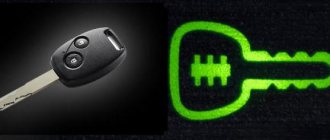
Lada 2107 सात › Logbook › Headlight button from figure eight (backlit)
Hi all. For a long time I had a light button lying around, with an illuminated symbol. And so I decided to install it, but the question arose about how to connect it, and I started looking on the Internet and on D2. But unfortunately I didn’t really find anything anywhere. After thinking about it, I decided to connect it on my own, with my minimal electrical knowledge. It turned out that everything was not so difficult, but I had to rack my brains, since there are many connection combinations in which the contacts are either constantly closed or are not closed as needed, and this happens in parallel with another row of contacts, in short, one source of plus is not enough, and the method At random, I found an option in which everything turns on like on the stock button, and does not require any changes in the wiring. I ordered the button on the Internet, since we don’t have them, and of course there are no chips here either, so I removed the old one and connected the terminals separately, having previously wrapped them with electrical tape so that they would not be accidentally shorted. I won’t describe everything specifically, where and when the plus appears, but where it is always there, I’ll just throw in a diagram, made in haste, that works, and everything is written there. The backlight works when the dimensions and, accordingly, the light are turned on, but when the button is turned off, it does not light up. I installed a diode light bulb, and connected the plus one accordingly, the light bulb is green (as it was), but then I’ll change it to blue, fortunately it will take about 30 seconds. By the way, the button came into place almost without any modifications, you just need to trim the clinging places a little, in short, everything is clear in place .
Stock option
Connection option
Scheme
www.drive2.ru
How to change standard lighting
Standard lamps can be replaced with more powerful and modern ones. The most suitable option is considered to be the main lamp for interior lighting, borrowed from Priora. To install it you will need to have:
- masking tape;
- sharp knife (can be a stationery knife);
- wrench 12;
- Screwdriver Set;
- pencil or marker for making marks.
Carefully remove the visor next to the rear view mirror
Please note that its weight is quite high, so if you are not careful, the ceiling may collapse completely. Outline the place of the new shade on the visor with a pencil, cut a hole along the contour. Secure the new lamp in this hole using sealant
Secure the new lamp in this hole using sealant.
Installation of a new interior lamp for VAZ 2107, VAZ 2105, VAZ 2104
Tuning the interior of a VAZ 2105 with your own hands, internal tuning of a VAZ 2107, tips for modifying the interior of a VAZ 2104, VAZ 2105, VAZ 2107. Tuning is a change and modification of the factory settings of a car. Tuning a VAZ with your own hands is a labor-intensive task, so we decided to share some instructions for modifying a VAZ 2104. Tuning can be cheap and expensive, superficial and deep.
The modification of the VAZ 2107 is considered in sections: interior tuning, suspension and steering tuning, braking system and body tuning, as well as engine tuning and gearbox tuning. First of all, when tuning a VAZ 2105, you should pay attention to the ignition system. The classic is a popular car that provides its owner with a wide range of tuning and modifications.
It's no secret that standard interior lighting - lampshades in the side pillars - is absolutely not enough. There is practically no sense from them. One lampshade was purchased from Lada Kalina
We remove the safety visor cover (Unscrew the rear view mirror, unscrew the sun visors, and two bolts on the sides (one under the handle cover on the passenger side, the second just under the cover on the driver’s side)). We remove the cover and take it home.
Remove the lid from the lampshade and draw the outline of the lampshade on a piece of paper.
And cut out the template. I cut the template 5 mm smaller than the contours of the ceiling - it’s better to cut the hole later than make a hole in the ceiling. We attach the template and cut out a hole with a knife. We try on the lampshade of the VAZ 2104 and see that due to the iron back side of the trim, the lampshade does not fit into the hole. Take a jigsaw and cut a hole in the metal along the contour.
We try on the lampshade while cutting the hole in the right places
We will also have to trim the front legs of the lampshade so that they are just below the metal level
The lampshade has a stop on the back side, but we need to secure it on the front side. To do this, I used a strip of iron and these screws with spacers instead of washers so that the spacers would not slip down (in your case, washers.). I made these fastenings from wire.
I simply heated the wire with a lighter and pierced the plastic with it. Then, inserting screws into the grooves, I screwed them to the iron spacer strip.
The entire lampshade is tightly secured. We insert the light bulbs and put on the cover.
And we take it all to install in the car. I took the power from the side lamp, laying a wire under the door seal of the VAZ 2105. (Be careful, 3 wires on the lamp are TWO MINUSES and one permanent plus) Well, the end result.
The central light burned so brightly that when it was turned on, the car windows became like a mirror. So I replaced it with a triple blue LED. The light from the side lamps is more than enough; by their light, you can read a book quite comfortably. You can also put aside a regular light bulb.
- And this is if you don’t install an LED, but leave the standard VAZ 2107 lamp.
Source: https://vazclub.com/vaz/2104-2105-2107/tyuning/salona/modernizatsiya-sistemi-osvescheniya-salona.html
Why the backlight of the VAZ-2107 instrument panel does not light up and what to do
What to do if for some reason the instrument panel lights of a VAZ-2107 car do not light up? This problem does not particularly affect driving safety, but still creates some discomfort for the driver. At night, it will be quite difficult for him to navigate by eye without seeing the tachometer, speedometer, battery or fuel charge level indicators, so it is better to fix the malfunction as soon as possible.
Replacing dashboard light bulbs
The first and quite logical problem due to which the instrument lights do not light up is the failure of all or just a few light bulbs at once. In this case, the only solution would be to replace them. It is performed as follows:
- The most difficult task will be dismantling the entire dashboard, which, unfortunately, is necessary to install new lamps. This, in turn, requires disconnecting all electrical connectors, the econometric hose and disconnecting the speedometer cable. You will also have to remove an additional panel, under which there are connectors for the cigarette lighter and the lighting system;
- we unscrew the failed control and illumination lamps;
- We install new products that are selected according to the characteristics specified in the vehicle specification.
If you intend to replace the torpedo backlight bulbs, you should know that there are only four of them. They are located in pairs at the top and bottom of the dashboard. In addition, control indicators are located under it, which allow you to see:
- fuel and battery charge level;
- indication of the inclusion of high beams and side lights, activation of the handbrake;
- indication of turn signal activation;
- lubricant pressure in the engine.
Instead of conventional incandescent light bulbs, which are installed by default at the factory, today you can use LEDs. They provide a range of benefits. Firstly, they last much longer and significantly reduce the load on the vehicle’s on-board electrical network. Secondly, you can significantly improve the appearance of the torpedo by installing LEDs of different colors. But such a replacement will cost a little more than installing standard lamps.
Other problems that cause the backlight to not light up
Bulb burnout is the most common, but not the only reason why the dashboard backlight fails. Therefore, we are ready to offer several options for solving this problem:
- failure of the dashboard backlight brightness control. This part breaks quite rarely and requires quite complex work to dismantle and replace. Therefore, if you are sure that this is the problem, you can at least temporarily transfer the positive wire from the side lights to the backlight bus. The regulator is located on the right side of the steering wheel next to the hydraulic optical correctors;
- combustion of fuses responsible for protecting the backlight system from voltage surges and sudden increases. They will need to be replaced, since these parts cannot be restored;
- break of resistance in the panel, which is usually caused by overheating;
- poor contact where the lighting system is connected to the on-board network.
Almost all of the problems listed above can be fixed on your own. If you have all the necessary tools and experience in removing the dashboard, the repair will take little time and will not create any serious problems.
Lada 2107 PHOENIX › Logbook › Replacing lamps in the dashboard
Perhaps one of the most noticeable tuning steps for the driver is dashboard tuning. There are a lot of recordings of this type on the drive, and it is quite possible that mine will be just another one... However, I will tell you about what I have not seen in other articles.
First you need to buy all the necessary components, in particular: Look at photo No. 3. On the left is what it was. On the right is what was installed.• LED lamps: 4 pcs. (bottom right) white light + 7 pcs. (top right) of which 3 pcs. red light, 2 pcs. green, 1 pc. blue, 1 pc. white.• Base (holder) for a small lamp. (top left)• 25 Volt electrolytic capacitor, 2000 - 4000 Microfarads
Next, you need to completely remove the dashboard and take it to a place convenient for work. In general, this is not difficult, but you will have to get dirty. You can search for how to do this on the internet, for example here: 2107club.ru.
After we have washed the panel from dirt, we proceed to modernization. For work you will need image No. 1. It shows the polarity for the LEDs using red and blue dots, which you need to know, otherwise the lamps will not work. You can check the polarity on the lamp itself “at random” using a 12-volt DC power supply or at least a 9-volt “crown”
(!ATTENTION: LEDs do not like polarity changes and may fail.). Personally, I used colored LEDs, however this is not necessary and you can use all white
We change everything except one - the low battery indicator, in image No. 9. This lamp cannot be replaced.
And now about the nuances. In several articles I came across the opinion that the green translucent caps in which the backlight lamps are located are not needed, supposedly because of them the light is dimmer. This may be so, but these caps are necessary for sealing so that dust does not get under the “glass” of the panel. I strongly do not recommend touching them. Moreover, the brightness with them is quite normal. True, they give an emerald tint of glow (seen in photo No. 2). Personally, in my case there were problems. The turn indicator lights up for a while after turning off the turn, after which it flickers a little. What this is connected with is not clear. I solved this problem in the wrong way: I soldered and glued the old lamp onto the board, parallel to the LED. I haven’t been able to solve the following glitch yet: the “dimensions/low beam” indicator glows faintly when the switch is in the off position. I tried to connect in parallel a fragment of the LED strip glued to the right side, but the problem remained. But now, when I turn on the headlights/low beam, the space behind the ventilation control levers lights up.
What is the capacitor for? And in order to eliminate the twitching of the fuel level needle. Connection diagram in image No. 1. If you need it, of course. It is worth noting that after this upgrade, when the ignition is turned on, the needle will rise smoothly until the capacitor is fully charged, and when turned off, it will beat to maximum. The severity of these effects depends on the capacity. The larger the capacitance, the better the smoothing, but the stronger the side effect. I do not recommend using a capacity less than 2000 and above 10000 uF.
Also, I soldered a 25 V 10000 uF capacitor in parallel with the dashboard backlight lamps. True, I already doubt its usefulness...
In image No. 2 you can see the areas outlined with a green marker, this is for those whose panel creaks. I applied two layers of adhesive tape to the plastic pins. I taped other contact points with black electrical tape. For example, along the edges of the “glass”, before returning the panel to its black body. And also the body itself, as well as the rim. So that the points of contact with the dashboard are “isolated”. No photos, sorry.
In conclusion, I will say that all the modifications are worth it. The panel looks livelier, newer, more modern.