There are 2 types of kits: original, designed for a specific car model, and universal. Built-in models If you decide to install heated seats in your car and want to use a built-in type, then you need to take into account that this method is difficult to install. We make the connection as indicated above. Of course, you can do this, but it’s one thing to install the system and forget it, and quite another to experience inconvenience with this very cover, which constantly falls off, fidgets around the seat, and gets in the way with protruding wires. In systems manufactured in China, switch buttons often break, short circuits occur, etc. Next, the fabric is pulled. heated seats. VW Passat b3. trade wind how to connect seat heating What is needed for this?
For an untrained driver, one seat usually takes about four hours. The heating areas are also different: some heat only the seat, others have a heated back.
Which one is better is up to you to choose! The standard heating warms the seat and lower back.
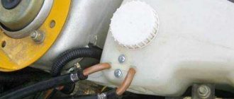
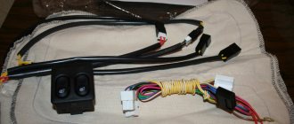
We fasten the mass to one of the 2 nuts, in this case the blue wire. There are operating modes - with the ability to switch power and maintain temperature automatically.
Detailed Installation of Heated Seat Do-It-Yourself from Sergei Zaitsev
Composition of a seat heating kit and how to install heaters on Granta with your own hands
Preparation for installation of heating elements
Before connecting the heated seats on the Grant, you need to secure the heaters under the upholstery of the seats. Of course, it is more convenient to do this on dismantled “seats”, previously disassembled into two parts: the back and the support. Creating acceptable conditions for installing heating elements is the goal of the preparatory stage. By the way, when determining the reasons for the knocking of hydraulic compensators, there is a slightly different logic.
Preliminary activities are carried out according to the following scenario:
- Disconnect the power supply to the seat belt sensor located under the seat. In many trim levels, this option is available only to the driver.
- Using an E10 head mounted on the knob, unscrew the four bolts connecting the base of the seat frame to the body and remove the seat. For ease of access to fastening elements, move the seat to the farthest or closest position. Similarly, remove and pull out the second front “seat” from the passenger compartment.
- Remove the backrest angle adjustment knob by prying it off with two flat-head screwdrivers.
- At the junction of the backrest and seat, remove the plastic covers on the left and right sides by unscrewing one screw each.
- Unscrew 2 bolts on each side securing the backrest frame to the metal base.
- Detach the backrest from the seat.
- Repeat steps 3-6 for the second chair.
Factory covers are attached to the frame with four clips. On the reverse side, the fixing elements are clamped with wires. Having untwisted the latter, we tighten the fabric. Before removing the backrest cover, disconnect the plastic lock at the bottom of the structure. When assembling, it is advisable to replace the wire with plastic clamps.
Installation of heaters
The purpose of preliminary positioning is to achieve such an arrangement of the heaters that the wires exit into the joint of the backrest and seat. You won't be able to play with the longitudinal base - the standard kit is designed strictly according to the dimensions of the depressions. After removing the protective tape, glue the element to the frame. If necessary, the foam is trimmed to allow the wire to exit unnoticed.
Fuses, list and description
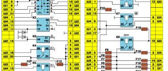
The electrical circuit of the Kalina-2 car can contain up to 38 fuses in total. The block installed under the hood contains 6 fuses designed for significant current. We, in turn, will consider the diagram of the main block:
All fuses in the electrical circuit of Kalina-2
- F1, 15A: ignition, injectors, power supply to the ECU and radiator fan relay;
- F2, 25A: power supply to the TsBKE unit and the front left door module;
- F3, 15A: electric drive of the automatic transmission, also power supply to the automatic transmission ECU;
- F4, 15A: power supply for airbag assembly;
- F5, 7.5A: speed sensor, brake pedal sensor, power supply to the instrument panel and ESD, ECM controllers, power supply to the automatic transmission selector, voltage on the windings of the unloading relay and the relay of the glass and seat heaters, power supply to the body electronics unit, washer switch;
- F6, 7.5A: power supply for automatic transmission electronics and reverse lamp relay;
- F7, 7.5A: voltage at the canister purge valve, at the phase sensor, mass air flow sensor, DC;
- F8, 25A: rear window heater and mirror heater circuit;
- F9, 5A: all “dimensions” on the right;
- F10, 5A: all “dimensions” on the left, license plate lights, keys;
- F11, 5A: rear fog lights;
- F12, 10A: low beam lamp, electric corrector for the right headlight;
- F13, 10A: low beam lamp, electric corrector for the left headlight;
- F14, 10A: high beam lamp on the right;
- F15, 10A: high beam lamp on the left;
- F16, 10A: “fog light” on the right;
- F17, 10A: “fog light” on the left;
- F18, 20A: seat heater circuit and cigarette lighter circuit;
- F19, 7.5A: ABS controller power supply;
- F20, 15A: signal;
- F21, 10A: fuel pump motor;
- F22, 15A: windshield and rear window washers, rear wiper;
- F23, 5A: power supply to the diagnostic connector, as well as to the instrument panel;
- F24, 7.5A: air conditioner motor-compressor clutch circuit, power supply to the air conditioner controller;
- F25, 7.5A: voltage at the brake pedal sensor;
- F26, 7.5A: ABS valve drives;
- F31, 30A: short-term switching on of high beams, power supply to the central bank, gear motor for front wipers;
- F32, 30A: heater fan circuit, power supply to the air conditioner controller.
Power supply or how to connect the heated front seats on the Lada Granta correctly
The cost of installation work at an unofficial service station is at least 2,500 rubles. For this money, already purchased heating elements will be installed in the car seat and the circuit will be connected according to the manual. All that remains is to make an anti-freeze product according to a home recipe and hit the road. This is for the quick ones. Painful owners will probably not like the electrical part of the integration.
Disadvantages of the standard kit
The instructions indicate how to install heated seats on the Grant and connect it to the on-board network. According to what is written, the electrics connect and function like this:
- The permanent plus is taken from the hazard warning button.
- The ground is connected to the bracket for fastening the standard wires of the negative pole.
- The standard fuse is replaced with a more powerful one.
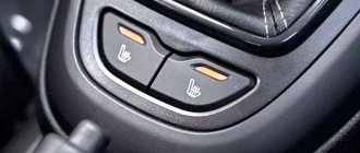
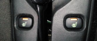
- The heating is turned on/off using the buttons directly.
Only one function is correctly implemented - turning off the heating when the ignition is turned off. Otherwise, the connection scheme is not entirely successful:
- The positive wire that goes to the emergency light is thin and will probably work at the limit.
- The contact group of buttons operates in a dangerous mode, since it is not intended for power loads.
For your information. The kit offers simplified buttons for installation - they do not have a power indicator in the form of a yellow lamp (as on the rear window heating control).
Competent connection diagram
An unfortunate result of the standard connection algorithm is a melted fuse. Such a reaction indicates that the circuit is operating at its limit. An alternative scheme for connecting heated seats will help to avoid this. It involves the use of two four-pin relays and powering them from switch K4, which supplies the output “+” after turning on the ignition.
Pinout of Lada Vesta: decoding of contact groups and equipment terminals
A complete set of car wiring is difficult to understand due to the abundance of connections and individual elements. For easier decoding, the wiring of the on-board equipment is presented below in individual parts.
Pinout of the front electrical harness
The front part of the wiring is 80% concentrated in the engine compartment and is responsible for the normal operation of the engine and the mechanisms that serve it. The following is the wiring sequence:
Pinout of Lada Vesta, section responsible for starting the power plant
A small part of the wiring is responsible for the main elements of equipment designed to start the power plant:
- 1 – generator block;
- 2 – standard fuse module;
- 3 – connection of the power supply element for on-board circuits;
- 4 – electrical part of the starter;
- 5 – sending a signal to the wiring of the front harness.
Vesta devices pinout combinations
All groups of contacts coming from on-board systems and sensors are concentrated in this part. The area is responsible for indicating the vehicle's status in real time.
- 1-3/9 – output to the disconnect terminal of the front equipment harness;
- 4 – on the aft wire bundle;
- 5/19 – device of the steering column switch – left side;
- 6 – electrical socket, protective element;
- 7 – standard steering wheel rotation degree sensor;
- 8/14 – protective insert for the door window lift device;
- 10 – standard key for headlight adjustment;
- 11 – insert for protecting the main fuel pump;
- 12 – similar insert responsible for the heater fans;
- 13 – relay for the device of external lighting units of the car;
- 15 – standard PPS sensor;
- 16 – button for switching operating modes of the cargo compartment lock;
- 17 – diagnostic block, designed to connect the external scanner;
- 18 – arrangement of a combination of fusible protective inserts inside the passenger compartment;
- 20 – driver airbag output;
- 21 – standard control key module located on the steering wheel;
- 22 – contact group of the airbag ring;
- 23 – ignition lock cylinder;
- 24 – antenna of the standard immobilizer system;
- 25 – pins for connecting accelerator pedal contacts;
- 26 – stop signal button is turned off;
- 27 – electric power steering device;
- 28 – contact group of the heating system fan;
- 29 – dashboard;
- 30 – cigarette lighter;
- 31 – on-board audio player;
- 32 – emergency warning button;
- 33 – dashboard push-button switches;
- 34 – module for monitoring and starting the interior heating device;
- 35 – standard front passenger airbag;
- 36 – glove box illumination lamp;
- 37 – control device for the GLONASS satellite navigation system;
- 38 – secondary heater operation control module;
- 39 – airbag activation device switch;
- 40 – button for turning on the glove compartment lamp;
- 41 – central module for monitoring the electrical equipment of the cabin;
- 42 – antenna for standard satellite navigation of the GLONASS system;
- 43 – audio system receiver;
- 44 – signal and power supply output to the aft part of the right auxiliary instrument cluster;
- 45 – a similar waterproof output to the second connector of the above element.
Pinout of the rear additional wire bundle
- 1 – parking sensor control system;
- 2 – contact group for connecting the rear bumper lines;
- 3-4 – output to the central bundle of wires;
- 5 – electric drive for the cargo compartment lid lock;
- 6-7 – license plate lighting lamps;
- 8 – lamp designed to illuminate the interior space of the luggage compartment;
- 9 – auxiliary stop signal;
- 10 – directly the servo drive of the trunk lid lock;
- 11/12 – left side of the stern lights;
- 13 – heating of the wind window of the rear part of the vehicle;
- 14/15 – right side of the illumination of the rear optics module.
Pinout of the rear on-board wiring block
Here is the equipment located in the rear of the vehicle:
- 1 – terminal connector designed for connection with the left front door;
- 2/7 – ABS system sensor, responsible for the rear right/left wheel;
- 3/6 – door position switches;
- 4/5 – fuel pump control unit;
- 8/9 – connector to block No. 2/1 of the rear auxiliary harness;
- 10/11 – outputs for connecting to the dashboard;
- 12 – control unit for car body panel equipment;
- 13 – cabin module for measuring internal temperature;
- 14 – plug block on the driver’s door;
- 15 – precipitation warning module;
- 16 – device for lighting the interior of the car.
Rear bumper wiring diagram
A separate part of the power cables designed to supply power to equipment located in the aft bumper:
- 1/2/4/5 – parking sensors;
- 3 – stern fog lights;
- 6 – connection device to the rear auxiliary wiring bundle.
ECM wiring connection
- 1 – reverse signal lamp switch;
- 2 – standard DPKV;
- 3 – electric clutch of the air conditioning compressor;
- 4 – electronic engine control unit;
- 5 – DCC;
- 6 – electric throttle drive;
- 7 – DTOZH;
- 8 – diagnostic oxygen concentration sensor;
- 9 – sensor measuring absolute pressure in the intake manifold;
- 10 – output of a control device indicating a critical drop in pressure inside the crankcase compartment of the engine;
- 11 – electromagnetic insert for controlling the intake position;
- 12 – plug output to the front wiring harness;
- 13 – electric generator;
- 14 – detonation channel length sensor;
- 15/18 – blocks for connecting the ECM unit to the injectors, sequentially for each drive;
- 16 – phase distribution sensor;
- 17 – to the ignition coils;
- 19-22 – ignition elements;
- 23-26 – injector drivers;
- 27 – standard capacitor.
Driver's door pinout
- 1 – electrical part of the door lock servomotor;
- 2 – threshold illuminator lamp;
- 3 – electric window motor-reducer;
- 4 – device for connecting fuse links;
- 5 – drive for controlling the position of the rear view mirror;
- 6/7 – areas for connecting high-frequency/broadband speakers;
- 8 – output to the rear wiring harness.
Important! The pinout is also relevant for the passenger door.
Connecting the manual transmission electronics unit
There are only five nodes, each of which is responsible for its own part of the mechanism:
- clutch module actuator;
- gear selection device;
- sensor measuring the speed of the drive shaft;
- gear shift mechanism;
- exit to the EBKP connection.
Vesta radio pinout
The standard connection block for the radio has 12 pins corresponding to individual elements. Moreover, each wire is painted in its own color for identification.
| Color | Meaning |
| Red | Supply voltage to the radio |
| Blue | Antenna power |
| Yellow | Connecting power when ACC is turned on |
| Black | Weight control |
| Violet/violet with black stripe | Rear right speaker +/- |
| Grey/gray-black | Front right speaker +/- |
| White/White/Black | Left front emitter +/- |
| Green/black-green | Rear left speaker +/- |
The pinout of the standard Lada Vesta radio is relevant for devices of most modern analogues. Consequently, there are no problems when replacing it, which guarantees a large selection of third-party models for modifying the machine.
CAN bus pinout
There are several outputs here and each of them is responsible for its own section of the diagnostic device:
- 2 – positive terminal;
- 4 – grounding of body panels;
- 5 – signal ground wire;
- 6 – J2284;
- 7 – K-line diagnostics;
- 10 – tire 1850;
- 14 – CAN-LOW 2284;
- 15 – diagnostic line L;
- 16 – voltage supply from the car battery.
Summary
The technology for installing heated front seats on the Lada Granta consists of two stages: installing heating elements under the factory seat covers and connecting them to the on-board electrical network. The proposed electrical circuit organization scheme raises doubts.
The manufacturer of the branded kit suggests connecting the heaters directly to the buttons, and powering them from the alarm control button. Since the circuit is quite loaded, it is better to organize the heating power through two relays with a separate fuse. It is also advisable to replace the buttons - they do not indicate the operating mode.
In the first part
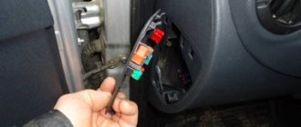
In this article, I described the introduction of a set of heating elements from the Alamara into the Granta seats. In the second part I will try to describe how we can connect them to the car’s on-board network. Let's figure out the connection together. Many connect heating through one or two relays. I had a small diagram included with the wiring harness for connecting the heating. There were no relays marked on it, just as there were no relays in the wiring itself. And the power was taken from the alarm connector. It was also indicated there that it is necessary to replace the original 5 A fuse of this circuit with a more powerful one - 10 A. Let's check if such a connection is safe: After installing the heaters in the chairs, I connected them to a powerful 12 V power supply to check their functionality . At the same time, I decided to understand the connection in more detail and make sure that this circuit is reliable and correct. I connected an ammeter to the circuit and measured the amperage under load. You can see the results in the photo:
As you can see above, with a heating power supply load for one seat, the current consumption is in the range of 2.4-2.5 A. We look at the maximum load current of our heating button - it is equal to 5A (Stamped on the button itself). That is, the current reserve for our button is quite large. The conclusion that follows is that the buttons can be freely used without a relay.
Do Two: Let's go shopping!
List of materials:
- Nichrome wire diameter 0.5 mm – 10 meters.
- The block is thicker.
- 2 nails.
- Old jeans.
- Scissors.
- Pencil.
- Sewing machine.
- Button.
- The wire.
- Plug for car cigarette lighter.
- Connectors.
- Heat reflector.
Nichrome wire can be purchased at almost any hardware store.
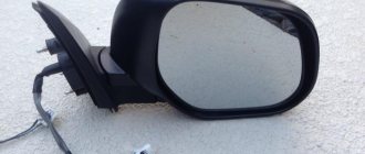
Installation of heating elements for heated seats
First, let's look at the mechanical part, that is, what needs to be done to install heating elements in the seats of the car, and then we'll look at the electrical connection of the heated seats. First you need to remove the seats. Everything is simple here. Just before unscrewing the driver's seat, look under it and pull out the seat belt indicator connector. To do this, press the connector latch and pull it towards you.
The seats are attached to the body with four bolts. The head of the bolts on Grant is a so-called “euro” head (E10). If you have a different one, take the corresponding key. Unscrew these bolts and remove the seats.
For convenience, we bring the removed seats home and start working with them at home. We disassemble the seats. We need to remove the backrest. To do this, turn the chair on its side. Take two flat screwdrivers. We insert them on both sides under the backrest angle adjustment knob and remove it by prying it up.
After that, using a flat screwdriver, we separate the two halves of the plastic caps. We do this very carefully, as you can accidentally break the guides.
Unscrew the screw holding the decorative trim. Let's take it off.
Take a 13 mm wrench. and unscrew the two M8 mm bolts securing the seat back to the base.
After this, we carry out similar work on the opposite side. Then we separate the halves of the chairs. Now you need to remove the factory seat covers. Let's start with the lower frame of the chair. We turn it upside down. The cover is attached to the frame with factory fasteners made of rigid wire.
They are easily released with pliers. To unclamp, you need to pinch the edge of the wire with pliers and twist it in a circular motion. The photo shows the places where you need to disconnect these same clamps.
After all the latches marked in the photo are released, we move the cover to the side and see the foam casting.
Now you need to release the seat back cover. There is a plastic lock at the bottom of the backrest. We disconnect it along the perimeter and lift up part of the cover. Turn the back over to the back side up. Under the cover you will see the same latches. It is necessary to remove four pieces, as in the photo.
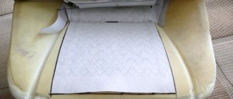
After the foam casting is exposed, we take our warmers, try them on and attach them. Let's start from the back. The backrest heating pad has a trapezoidal shape, just like the space on the backrest for heating our chair. But it matches the chair only upside down, with the wire facing up.
Options
First, it’s worth considering which seat options can be used in the VAZ 2107. Here you need to take into account the mounting features, as well as the dimensions of the seats. After all, this item should not only match the fastenings, but also fit normally in the cabin. There are examples when the seat is too high or interferes with driving. Therefore, you need to make your choice very carefully.
Many drivers claim that seats from a 1996 Mercedes W210 are optimally installed in this model. Such seats can be seen in many “sevens”. Moreover, the owners claim that no modifications were required for installation. Everything fit into the fastenings, as if it had been specially designed.
You can install seats from a 1993 Toyota Corolla in a similar manner. This option also does not need to be modified. We just install it, fasten it in the standard way, and move on. All fasteners fit perfectly.
If desired, you can install almost any seats from Skoda and Fiat. They are completely the same in terms of the size of the sled, as well as the main fastenings. But, there is one caveat. These seats have a slightly shifted center of gravity. Therefore, for greater stability and reliability of the resulting structure, it is recommended to add a couple of additional holes for fastening on each side.
Without modifications, you can install seats from Volkswagen, but this option is practically not used in practice. The reason is that the seat height is too high, making it inconvenient for drivers to operate the car.
It is also possible to supply options from Peugeot and Nissan. But there are a number of difficulties here. Installation will require a lot of reworking of the fasteners, which will take quite a lot of time. There may also be problems with seat settings.
Connection of heating elements for seat heating diagram
Now about the electrical connection. Everything seems simple here. I took a switch of the required current and voltage rating, and connected everything in series. But you would be warned against this option. The whole point is that human essence sometimes manifests itself in forgetfulness. This means that leaving the heated seats on once while the car is parked can completely drain the battery. Here it is best to ensure dependence on turning off the ignition switch. That is, if the ignition switch turns off, then so does the heated seats. This is easy to do using a relay. The winding of which will be triggered by turning on the ignition switch, and from the sequentially installed heating switch button. Such a scheme will have two advantages. The first is, as we have already said, turning off the ignition in the car. Second, independent connection for power currents after the ignition switch. That is, the switching current of the relay will not significantly affect the currents after the ignition switch, and therefore will not cause the fuses to blow in the mounting block.
So, we offer you the following scheme.
Yes, there is a minus here. This means that it is generally better to make the circuit switch off after some time, but this will complicate it. This means that not all car enthusiasts will be able to repeat it. However, what is most important is that, in general, the scheme is quite workable.
If, after all, you make a circuit with a timed shutdown, then about this in the article “Do-it-yourself timer in a car.” And even a video on this topic.
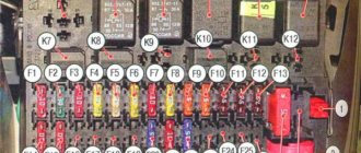
Fuse layout diagram for VAZ 2110, 2111, 2112
The photo shows fuses for VAZ 2110, 2111, 2112
As you can see, each fuse is numbered with a corresponding index. In the above illustration, the unit is located on the left side of the steering column and is integrated into the instrument panel. Below are the values of the specific fuse in this mounting block.
Table of fuse values for VAZ 2110, 2111, 2112.
Fuse and relay box
The fuse and relay box is located on the left, lower part of the instrument panel. It is accessible by pressing the button and folding the lid down. To remove fuses, there are special non-conductive pliers in the upper left part of the mounting block.
1 - K5 - high beam relay . If the high beams in two headlights do not work, check this relay. If one of the high beam headlights does not work, check fuses F3 and F13, as well as the lamps and the high beam switch.
2 - K4 - low beam relay . If the low beam in both headlights does not work, check this relay. If only one low beam headlight does not work, check fuses F2 and F12, as well as the lamps themselves and the light switch.
3 - K1 - lamp health control relay.
4 - non-conductive tweezers for removing fuses.
5 - power window relay . If your power windows stop working, check this relay. It could also be in fuse F5, or in the window lift drive system itself. To get to the mechanism, you need to remove the door trim. Check the electric motor, the appearance of the gears and the absence of binding of the mechanism.
6 - K3 - turn signal and hazard warning relay . If your turn signals or hazard lights do not work, check this relay and fuse F16, as well as the turn signal lamps themselves and their switch.
7 - starter relay . If the car does not start and the starter does not turn, check this relay. It could also be a dead battery, as well as the starter mechanism itself.
8 - backup fuses.
9 - fog lamp relay . If the fog lights do not work, check this relay and fuses F4 and F14. Also check their connection diagram, the serviceability of the wiring and connectors, as well as the lamps in the headlights and the power button.
Replacement features
Briefly about the procedure for replacing the control module on Kalina 2:
- First, the instruments are dismantled from the center console; there is nothing difficult about it.
- Then the lower part of the center console trim is unscrewed, the trim is removed, and you gain access to the fuse and relay box.
- The mounting block with safety devices can be unscrewed, but it cannot be removed because it is connected by wires. You can rotate it a little so that it takes a horizontal position.
- You can stick your hand into the gap formed as a result of turning. Having done this, you will be able to feel the shelf on which the TsBKE is installed. A little to the left there is a bolt with which this module is fixed - you need to unscrew it.
- After this, through the top, through the instrument panel, you will need to disconnect the two connected connectors. After completing these steps, you can carefully dismantle the CBKE and remove it by slightly moving the fuse box. Please note that you should not pull the device too hard, since there are two more connectors on the other side that will need to be disconnected. When the wires are disconnected, the CBKE can be completely dismantled and repaired or replaced.