Any modern car is equipped with a control module - an electronic unit that allows you to ensure the most optimal operation of the engine. As a result of incorrect operation of the ECU, problems may arise in the operation of the vehicle. What is the VAZ 2114 ECU, where is it located and how to replace it yourself - find out from this material.
Description of "brains"
The VAZ 2114 ECU is an on-board computer of the vehicle, designed to control the main systems of the car. The parameters of the control module affect both the functionality of certain regulators and the operation of the engine as a whole. That is, the importance of this system cannot be denied.
Controller Location
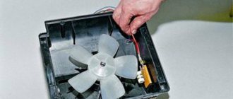
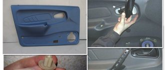
In VAZ 2114 and VAZ 2115 cars, the control module is installed under the center console of the car, in particular, in the middle, behind the panel with the radio. To get to the controller, you need to unscrew the latches on the side frame of the console. As for the connection, in Samar modifications with a one and a half liter engine, the mass of the ECU is taken from the power unit housing, from the fastening of the plugs located to the right of the cylinder head.
Location of the ECU in the Chetyrka
In cars equipped with 1.6- and 1.5-liter engines with a new type of ECU, the mass is taken from the welded stud. The pin itself is fixed on the metal body of the control panel near the floor tunnel, not far from the ashtray. During production, VAZ engineers, as a rule, do not securely fix this pin, so over time it can become loose, which will lead to the inoperability of some devices.
Design and principle of operation
The control unit of the electronic system operates in accordance with the indicators received from the sensors:
- speed;
- detonation;
- lambda probe;
- fuel injection phases;
- crankshaft position;
- throttle position;
- air flow meter;
- antifreeze temperature.
In accordance with the data received from these controllers, the control module controls the following systems:
- ignition;
- adsorber;
- injectors, as well as a fuel pump;
- ventilation and heating system;
- programs for diagnosing vehicle performance;
- idle speed regulator (video author - Evgeniy Vekhter).
As for the device, the control module structurally consists of the following components:
- RAM or random access memory. This module contains basic data about recently identified errors detected by the electronic system in the operation of various components. When the driver turns off the ignition, the RAM unit is updated, causing this data to disappear.
- PROM is the main element of the system; it contains the firmware of the control module. It should be noted that this memory block contains all the necessary data on the calibration of the “four” systems along with the general engine control algorithm. Unlike RAM, EPROM is a permanent memory, so the data stored in it is retained even after the ignition is turned off. If necessary, this module can be reconfigured, that is, reprogrammed, which can lead to improved power as well as vehicle dynamics.
- ERPZU - the primary function of this module is to protect the car. The EEPROM memory contains information from the anti-theft installation - passwords, as well as encoding of the main parameters. Starting the engine will only be possible if the EEPROM successfully checks with the data contained in the immobilizer memory.
Typical malfunctions: their symptoms and causes
What are the signs that indicate a faulty ECU:
- there are no control signals coming from actuators (IAC, flow meter, various sensors, etc.);
- there is no signal for interaction with the ignition system, fuel pump, injectors and other elements;
- when connecting a diagnostic tester, there will also be no connection with the electronic system;
- Burnt contacts and mechanical damage to the device may also be a sign.
What reasons contribute to the failure of the control device:
- electrical circuit shorted or broken;
- improper electrical repairs, during which errors were made, in particular, we are talking about installing or repairing an anti-theft system;
- lighting a dead battery from a car with the engine running;
- a breakdown of the unit can be caused by incorrect connection of the battery terminals - plus instead of minus and vice versa;
- disconnecting the battery contacts when the engine is running;
- moisture on the electronic system module board;
- mechanical damage to the device as a result of an accident (the author of the video about repairing the control module in a garage is the Auto Practice channel).
What to do if the starter does not turn the engine from the ignition switch
If when you turn the ignition key the car does not start, and nothing happens at all, in some cases you can correct the situation by supplying power to the starter, bypassing the lock. This solution is suitable for cases where the electric motor itself and the solenoid relay are in good working order. In this case, you need to proceed according to the following algorithm:
Control wire terminal
- Turn on neutral gear and ignition.
- Find two terminals on the starter: a thick power wire from the battery positive and a thin control wire from the control relay.
- Using a metal object (screwdriver, key, wire), close the power and control contacts.
- After the starter operates and the engine starts, immediately open the contacts.
An alternative to the same method is to supply power to the starter control terminal directly from the positive terminal of the battery. This can be done using any insulated wire, for example from a cigarette lighter wire kit.
The lack of response of the starter to direct power supply indicates its breakdown, failure of the electric motor or the solenoid relay. To diagnose the starter, you need to disassemble the starting unit, inspect the brush assembly, armature and stator windings. This is not easy to do in the field and without a multimeter, so you need to push the car and get to the garage or service station.
When the starter turns directly, but not from the key, then the starter itself is fully operational, and the problem lies in the electrical circuit from the key to the starter. To determine the location of the breakdown, you need to follow the instructions given below.
How to look for the reason if the car does not respond to the ignition key - instructions:
How to start the engine by jumping the starter directly: video
- The characteristic light click of the triggered starter relay when turning the key to the “start” position in most cases indicates the serviceability of the ignition switch and its contact group. Next, you need to look for the problem in the engine compartment.
- To check the solenoid relay, you need to connect a wire to its control terminal (a terminal with a thin wire) directly to the “+” terminal of the battery. A working relay should click and push the bendix towards the flywheel, and also start the starter rotating. The presence of a clicking sound without cranking the starter is a sign of poor contact of the power wire or a malfunction of the starter motor itself.
- You can check the serviceability of the motor by directly closing its retractor power contacts - they are made in the form of large diameter pins. If after this the starter spins, the retractor winding is faulty or it is jammed.
- For more detailed diagnostics, the solenoid relay must be removed from the starter and disassembled. First of all, look at the contact “nickels”, which can oxidize and burn. If there are traces of these processes, you need to clean the contacts, assemble the relay, return it to its place and check the operation of the starter. If everything is clean, you need to check the solenoid winding, for example, by ringing it with a tester for a short or open circuit.
What to do if the starter does not respond to the ignition key: video
ECU diagnostics
The VAZ engine control unit is a device that can operate for a long time without breakdowns, however, no equipment can be protected from malfunctions. When the first symptoms of failure are detected, the device must be diagnosed, since untimely inspection and repair can lead to more serious consequences. Device diagnostics involves reading error codes stored in the device’s memory for further decryption.
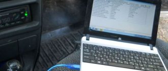
It is best to check the ECU in specialized centers, since the diagnostic equipment must be configured for a specific ECU model. Of course, the diagnostic procedure can be carried out on your own - using a computer, diagnostic adapter and software.
In the event that the ECU does not respond to the test, its performance should be checked, in particular:
- diagnose the device for overheating;
- make sure that the device is connected to the power circuit and that its contact with the on-board network is good;
- diagnose the mechanical integrity of the device - it is quite possible that there is damage to the device body, or the reason may be the formation of corrosion.
Remember that it is impossible to perform high-quality repairs of the control unit at home . It is better to entrust the repair procedure to specialists, and not from any service station, but from certified centers.
Photo gallery “Do-it-yourself ECU replacement”
Hard case
Until now, situations have been sorted out when the torpedo still showed some signs of life. If non-working power windows, turn signals, and windshield wipers have been added to the devices, the issue is no longer a matter of relays and fuses.
There may be 2 options:
- The contacts on the ignition switch are burnt. In principle, after installing the relay (even on the VAZ-2109 version), this problem rarely arises. However, the possibility remains. The lock is removed, the contacts are checked and, if necessary, cleaned;
- Mounting block. There may be burnt tracks on its board. The only thing that will save you is replacing it with a new one. However, the cost is by no means astronomical, and the installation is available as a standalone option.
Video “Instructions for replacing the electronic unit in a VAZ 2115 yourself”
If you decide to replace the ECU, then this task can be done at home - detailed instructions for replacing the device yourself are presented in the video below (the author of the video is the AVTO CLASS channel).
How the mass of the ECU and the mass of the engine - body are arranged, where it is located and how to check it. It is these interesting questions that we will address on this page.
The topic is really interesting and not as simple as it seems at first glance.
It would seem that there is nothing complicated here - a simple circuit and a rather thick wire, with which it is unlikely that anything can happen. But not everything is so simple, and we will “talk” about this further.
ECU weight
A reliable ECU ground is very important for the proper operation of the engine management system and the engine as a whole.
It would seem to be a primitive and reliable design that can serve well for years. But in reality this is far from the case.
It is very difficult to list all the possible problems that can arise due to poor ECU mass, since it can affect anything. But the main problems can be divided into two points:
- Incorrect collection of information from engine control system sensors. Personally, I had to deal with incorrect MAP sensor readings. It gave inflated barometric pressure readings precisely because of the poor weight of the ECU.
- Since almost all modern engine control units are able to adapt to real operating conditions, as a result of incorrect collection of information from sensors, adaptation leads to engine malfunctions. This is why for many, after resetting the adaptations, the engine begins to work much better. But then the problems return as the ECU adapts again. And again this does not happen quite adequately.
Pressure check
If the pump is working properly, but the engine begins to operate intermittently, you should check the fuel pressure in the system. For this you will need:
- pressure gauge (can be a tire gauge with a measurement limit of 5–7 kPa);
- petrol-resistant hose with a diameter of 10–12 mm and a length of 50–80 cm;
- two clamps for a hose of the appropriate diameter;
- Phillips screwdriver;
- nipple cap;
- dry rag.
In addition, the presence of an assistant is desirable.
The verification procedure is as follows:
- In the engine compartment on the engine fuel rail, locate the pressure measuring fitting (on the right side).
- Remove the plastic cap (plug) from the fitting.
Find the pressure fitting and remove the cap from it
- Using the nipple cap, unscrew the spool valve from the fitting. When unscrewing the spool valve, fuel may spray out of the fitting. To remove it, use a dry cloth.
Where is the ECU ground located?
The ECU mass is usually arranged like this. Separate ground wires are removed from the ECU connector and connected to the engine via the starter mounting bolt. Ground wires are usually black
Everything is simple and reliable. But in reality, over time, the voltage begins to drop in this section of the circuit, slowly but surely, disrupting the operation of the system.
Therefore, this unit must be periodically checked and maintained. We will look at how to do this further.
Weight between engine and body
Line “31”, popularly called “ground”, “minus” or “negative circuit”, is very important for a car. And not only for electrical equipment, but also for many other systems, including the engine or automatic transmission.
Almost all cars have a single-wire on-board network system and the role of the “minus” in this circuit is played by the metal parts of the body. This greatly reduces the number of wires and reduces the cost of the car.
It turns out that all participants in this chain have their own connection to the body - instrument panel, headlights, ECU, engine, etc.
Despite the visual integrity of these connections, over time, due to oxidation and corrosion, the contact slowly and imperceptibly deteriorates, which leads to voltage drops when powerful consumers are turned on or disruption of the system.
I would divide the mass connections into main and local. Let's say that the connection of the head light masses is local and if this connection is disrupted, only the head light will suffer. But if the ground contact from the battery to the body is broken, the entire on-board network will suffer, and this may cause problems in the operation of the engine and other important components and assemblies.
This is how the voltage of the on-board network with problematic masses looks like on the diagnostic graphs
And here is the graph after mass prevention of battery - engine - body
Therefore, a reliable engine-body mass is very important for the proper and trouble-free operation of the entire vehicle.
And the mass of the ECU - engine is even more important, since the voltage in the engine control system does not exceed 5 V. Therefore, this further encourages owners of cars with an engine management system to take the issue of mass more seriously than owners of carburetor cars, where the voltage is 12 -14 B. Because the lower the voltage, the greater the damage from losses in the circuit.
In general, the ground chain must be maintained in perfect condition. It's like an axiom.
Next, let's look at where the engine-body mass is located and how to check it.
Why does the starter not respond to turning the ignition key?
After turning on the ignition, power from the battery is supplied to the on-board electrical systems and the computer (if equipped). If there is an immobilizer (standard or an installed security system), this occurs only after the tag is recognized. When the key is turned to the start position or the start button is pressed, the contacts of the solenoid relay are closed, resulting in power being supplied directly to the starter. At the same time, the starter overrunning clutch (Bendix) engages with the flywheel crown, setting it in motion and ensuring the engine starts. Often, switching is carried out through an additional starter control relay, which removes the load from the lock.
Ignition switching circuit
If a problem arises at any of the above stages, the car will not start: you turn the ignition key and the starter is silent. As a rule, the reasons for this behavior lie in:
- ignition switch contact group;
- alarm and immobilizer;
- control relay;
- wiring from the control relay to the starter;
- starter solenoid relay.
More information about why the starter does not work with the ignition key can be found in the table.
The starter does not work from the ignition key: reasons
| Problem | Cause of malfunction |
| Starter motor faulty | The electric motor fails due to overheating, short circuits in the windings, wear of the brush assembly, and jamming of the gearbox. |
| The circuit from the ignition switch to the starter solenoid relay is faulty | Wiring break or short circuit. Often occurs after repairs, installation of additional equipment, or as a result of mechanical wear during long-term use. |
| Damage to the ignition switch (deformation of the cylinder) | Deformation due to overheating, which in turn occurs due to poor contact. Damage is also possible due to the mistaken use of an inappropriate key. |
| Electrical malfunction of the ignition switch contact group | The layer of oxides formed on the contacts prevents the flow of current. Also, the contacts may move away due to deformation of the rotary sleeve on which the mating parts are attached. |
| Start blocking by installed alarm | A voltage surge in the on-board network or loss of power (disconnection of a terminal or discharge), failure of a transistor or microrelay responsible for turning on the start line in the base unit of the security system. |
| Immobilizer malfunction/decoding | Voltage drops and sudden loss of power (battery discharged or terminal removed), software failure, failure of microelements. If the immobilizer does not recognize the mark, the starter does not turn after turning the ignition key, and the immobilizer symbol usually lights up or flashes on the indicator panel - an image of a car with a key or lock. |
| Failure of the solenoid relay | Burnout or short circuit of the winding as a result of overheating due to the flow of increased current or being under load for an extended period. The root of all problems is usually oxidation of the internal and external contacts of the solenoid relay. |
| The limit switch for the automatic transmission selector position, the brake pedal for an automatic transmission or the clutch for a manual transmission is faulty | Sensors fail due to mechanical wear, and their wires and terminals can oxidize or fray. Because of this, the ECU does not allow the starter to start. |
| Starter relay failure | If the starter control relay is stuck or shorted, it cannot supply power to the control terminal of the solenoid relay. |
| Poor “+” contact from the battery on the starter | The power contact terminal oxidizes under the influence of moisture and heat. The nut that holds it to the starter stud can come loose due to vibrations. |
| Poor ground contact at the battery terminal, car body or engine | Due to oxidation, the contact of the ground wire deteriorates; the same thing happens when its nut is unscrewed under the influence of vibration. In this case, the passing current may be enough to turn on the on-board network and the ECU, but not enough to drive the starter electric motor. |
Where is the mass located: engine - battery - body
On most cars, the engine-body mass has a primitive appearance and is made of two pieces of cable connected together by crimping on the negative terminal of the battery
This crimp connects two wires. One goes to the engine and is secured with the starter mounting nut...
...and the second one on the body in the area of the left wing
It would seem that this is the simplest and most reliable chain that will serve well for years. But this is not at all true and it’s all to blame for the weak points in this design, which do not withstand the test of atmospheric influences.
How to check mass on a car
In fact, only a small group of motorists pay enough attention to this issue. Others begin to think about it when, when the cooling fan or headlights are turned on, the engine speed begins to sag, or when the rear window heating is turned on, the engine begins to tremble, transmitting vibration throughout the body.
But even at this stage, many limit themselves to a banal inspection and tightening the ground connection nuts on the engine and body. Everything is screwed down - that means everything is in order.
Then the car begins to jerk for no apparent reason, idle speed freezes, misfires, security system glitches, and so on, until the starter fails at the most inopportune moment. But even here, many will not go check the masses, but will run to the store for a new starter. After all, the wire to the starter is intact and there is voltage, but it, a radish, does not turn.
Replacing the starter, of course, does not help. As a result, the still-living battery goes into recycling and the situation seems to have improved, but after a couple of days the starter fails again and you begin to believe in brownies and otherworldly forces that have nothing better to do than cause damage to someone else’s car.
But, fortunately, reason wins and the advice of a good man is remembered - to check the masses.
Again, what's so difficult about this? It is necessary to check the resistance from the engine to the body.
How to check mass with a multimeter
Disconnect the negative terminal of the battery
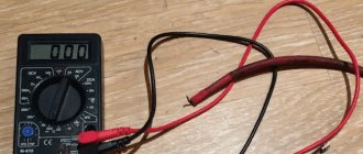
We take a multimeter and switch it to resistance measurement mode up to 200 Ohms. We check the resistance of the probes themselves by connecting them together
The resistance of the probes themselves is 2.1 Ohms.
Now we connect one probe to the engine. At least here
And the second probe is to the engine control unit, which, in turn, is screwed to the body
We look at the multimeter readings. So what do we see? But we usually see the same 2.1 Ohm
What happens - the mass resistance of the engine - the body has practically no resistance? Is everything perfect? Is the engine and body weight OK? What is the problem then? Is the starter defective or are otherworldly forces overcoming you?
The whole thing is much simpler. What is a mass chain in the understanding of an ordinary person? This is just a piece of wire that connects the engine to the body. Just a piece of wire! If we connect ohmmeter probes to the ends of this wire, then we will find out its resistance. It will be minimal - it’s just a piece of copper wire. Right? Right.
If we connect the voltmeter probes to the ends of this wire, we will see zero voltage. After all, where will the potential difference come from on a single piece of wire? Right? Right.
Now let's connect our voltmeter to this ground wire on the car. That is, as when measuring resistance, one probe is to the engine, and the second to the body. They are connected by this piece of wire. Right? Right.
We switch the multimeter to the mode for measuring constant voltage up to 2 Volts. We start the engine and look at the device display.
Oops. And we have tension!
How can this be - we are connected to the ends of one wire, and we have voltage.
So I showed off my artistic creativity and painted a picture of what was happening
Red is the ground wire, and blue is the voltmeter
These values on the multimeter display are nothing more than the voltage drop on our ground wire! Even though it looks great and has minimal resistance, it still drops voltage. Moreover, the greater the consumer current in the circuit, the greater the voltage drop on this wire will be, which can reach several volts!
This is the situation. And the mass of the engine and body is not as good as it seemed at first, and problems from it are inevitable.
How to come out of such a situation as a winner?
First, it is necessary to periodically service this section of the chain.
Unscrew the mass on the body
Do the same with the mass on the engine.
But this doesn't always help. The fact is that this chain still has weak points - crimps.
Crimping lugs, crimping on battery terminal
All this oxidizes over time and cannot fully perform its function.
Instrument needles are jumping
It often happens that they simply start jumping on a scale from minimum to maximum. Typically, the cause of such a malfunction is a poor connection between the contact and ground. Its wire coming from the shield is fixed on the partition separating the engine compartment from the passenger compartment. You can find it by removing the radio from its socket. But if an alarm was installed on your car, most likely, the fastening of this wire was moved to a more convenient place for greater convenience. Usually, experts move it behind the interior trim, not far from the driver’s left foot.
Car owners can expect the same thing after installing a radio. At the moment of fixing its negative cable, perhaps the ground wire of the shield was poorly wrapped. As a result of this oversight, under the influence of vibrations transmitted to the car body, the cable could become loose. This happens very often, and for a long time car owners cannot understand why the dashboard on the VAZ-2010 does not work. It is worth saying that even specialists often wrap the mass wire poorly due to the fact that doing so is not entirely convenient.
If the fastening of this cable turns out to be of good quality, it is worth checking the shield itself. To do this, it must be removed from the place of fixation so that you do not have to disconnect the wires going to the pads.
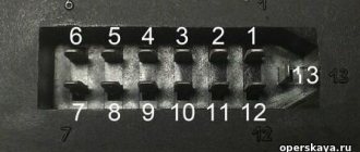
You need to check the mass cable on the white block X1, going to the first contact. In addition, it is worth checking the voltage on pins 9, 6 and 10 - it should be at least 12 volts
In addition, be sure to pay attention to the condition of the tracks at the back of the panel, along which impulses are transmitted to consumers
Power supplies
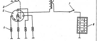
On the vast majority of modern cars, the power source is a three-phase alternating current synchronous generator driven by the main engine; three-phase alternating current from the generator is supplied to the built-in three-phase rectifier and voltage regulator circuit - in modern cars the voltage regulator is built into the generator housing. A car battery is used to provide constant and continuous power to some consumers when the engine is not running, such as lighting, car radio, brake lights, anti-theft alarm, as well as to fully power all vehicle systems when the engine is started. After starting the engine, the battery is recharged from the generator, and then it works in a buffer with the generator, smoothing out voltage drops when connecting powerful consumers. The generator power of a modern middle-class passenger car ranges from about 900-1300 watts.
Older cars used DC generators that were larger and heavier than three-phase generators; To maintain a constant voltage, a relay regulator was used, consisting of three devices - a voltage regulator, a current limiter and a reverse current relay.
In a number of cases, on special-purpose vehicles, as well as on armored vehicles, an additional generator driven by a separate internal combustion engine (the so-called auxiliary power unit) is installed, which makes it possible to supply consumers with electricity regardless of the operation of the main engine.
These include: switches and switches, relays, fuses, connector blocks, distribution and switching boxes, as well as power units.
Yuri Petrovich 12/10/2009 - 15:45
(Cat 302 @ December 10, 2009, 1:42 pm)
The crankshaft position sensor has died, and if there is no signal from this sensor, the controller blocks the fuel pump circuit!
(Cat 302 @ December 10, 2009, 4:13 pm)
It happens Yuri Petrovich. So, on the highway to NG, I’m going out of town to celebrate, I stop for a little emergency, smoke the car in the wilderness, don’t start, I listened to the pump, it’s not making noise, and purely by chance a friend was driving by and it saved me, they brought services, no tools, no tools in the cottage, we went for the DPKV, it didn’t help, we hooked it up directly with wires it works, on holidays we took it to a local service center, where the controller immediately gave an error: a short circuit in the fuel pump network, they replaced the relay, everything rang smoothly, the error remained, the technician came to the conclusion that the controller had burned out and, purely for the sake of experiment, they tried to fix it and lo and behold, the pump started working.
a friend on a new fourteenth car died after six months on the highway, it was cured by replacing the relay, first the relay should be changed Post edited by Rino: 12/10/2009 - 19:33
All ground mounting points for the VAZ of the tenth family
| If the electrics in the car start to malfunction, then one of the reasons for this ailment may be poor fastening of the battery mass. Ten have features of mass fastenings depending on the engine and year of manufacture of the car. We check all the attachment points of the negative wire: |
Location of masses in the car interior
| 1 - fuse block.2 - near the driver’s right foot there is a shield, which is attached with a couple of screws, removing it, you will see that everything is like in the picture.3 - in principle, the situation is similar to the point described above, except that the shield is located next to with the left leg of the navigator. |
| The stud in the dashboard behind the mounting block, in order to find it, you need to bend in a certain way. The headlight hydraulic corrector is shown there for reference; the ground pin is located above and to the left of it. Through this mass, the windshield wipers, heater fan (21124) and door lock activators are powered. |
| The console is on the right side, from here it is more convenient to check the very important ground pin, through which the bracket under the ECU is connected to the car body, and accordingly the reliability of the ground of the ECM and the cooling fan depends - this nut also holds the corner that supports the far part of the left panel of the console. |
| ECM harness mass crimps in the console. The connector was removed from the ECU and pulled out onto the driver’s mat, it’s more convenient. I bit the fan ground wire out of the ignition circuit crimp (left in the photo), extended it, put the tip on and connected it separately to the bracket. I soldered all connections for reliability. |
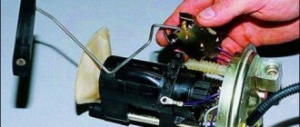
| Weight of the Electric Fuel Pump (EFP) module and fuel level indicator. A black and white wire is attached to the left rear handbrake lever mounting bolt under the floor tunnel. The fuel pump is powered through this mass, and the accuracy of the fuel level reading also depends on it. |
| The ground is on the stud of the fuel pump flange; this wire most likely connects the pump housing to the fuel filter bracket and this was done for safety reasons to equalize the potentials of these two devices. |
It is easy to find the ground of the electric fuel pump module without removing the tunnel; just fold back the mat, slightly bend or carefully trim the carpet of the floor behind the driver's seat below the ashtray of the rear passengers, without damaging the ground wire itself. Then the carpet easily falls into place and the cut is almost invisible.
Location of masses under the hood of a car
The battery terminal is large and thick with a large cross-section wire (approximately 16 sq. mm). Its thick part, about the thickness of a little finger, connects the negative battery and the engine. If the contact of this wire is unreliable, there may be a deterioration in the battery charge, a decrease in the starter rotation speed when starting, as well as problems in the ECM system, because the minus comes from the engine, from the studs on which the ignition distributor hung on carburetor cars.
| The thin wire connecting the minus battery and the car body is the main connection for all electricity consumers in the car, and in carburetor modifications also for the engine. Through this connection, all the car's lighting equipment, radio and other devices are powered, depending on the year of manufacture of the car. |
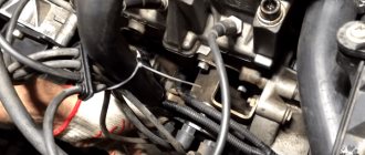
| The connection point for the negative terminal of the battery to the engine block is connected to the upper stud of the thermostat, if you look behind the air filter. The cross-section of the wire was chosen based on the large current consumption of the starter; this wire can easily be traced by hand if it is led from the battery. The starter current flows through this wire, charging the battery, some sensors screwed into the engine block are connected through it |
| Nearby there is another ground connection point to the engine block, it is slightly higher and to the left. The 2112 engine has two brown wires connected to this place - this is the mass of the ECM, that is, the mass of the sensors, ignition module, ECU and cooling fan. The arrow below shows the engine (starter) ground wire from the battery. |
| The mass point under the adsorber - Miha [email protected] suggested that this is the mass of the right headlight and the mass of the right fog lamp. |
The most common breakdown
Before digging into the inside of the car, check how securely the ground wire leading to the front panel is secured. A restless passenger in front often simply pulls him out of his place with his feet. To prevent the situation from repeating itself, after fastening it is worth insulating the wire from reach. The situation is a little more complicated
Its signs are very characteristic:
- All indicators do not work:
speedometer, tachometer, odometer, fuel level recorder, coolant temperature sensor; - The rest of the equipment - optics, radio, even the panel backlight - turn on normally and do not act up;
- The ignition works properly, the car does not refuse to start;
- Fuse F3 is
almost 100% . It is located in the mounting block and will have to be changed. But first you need to find out why it was covered, otherwise the new one installed will suffer the same fate. In most cases, a short circuit is to blame for burnout. On well-used VAZ-2114, the fuse often blows after each wash. Instead of carrying a spare one, you need to figure out where moisture is getting into it.
If the fuse is intact, this is not a reason to immediately leave it alone. It would be a good idea to remove it and check the contacts: if the fuse is live, but the terminals are oxidized, the circuit will be interrupted, and the device will stop showing any signs of life.
How to improve the mass of the VAZ ECM
| If you notice that the engine speed fluctuates when the radiator fan is turned on, a possible reason is insufficiently reliable contact of the ECM ground with the vehicle ground. This is a known problem with the VAZ 2110 and VAZ 2113-2115 of the “new” model, in which the fan is controlled via a ground wire. We find out how to modify the weight of the car. |
Tests were carried out on a VAZ 21114, 2005 onwards, with a mileage of 7500 km, 8kl, 1.6l. Problem: When the car engine is warmed up, and the TPS position is 1-2%%, then at idle there is a noticeable (100-200 rpm) ) speed drift when the electric cooling fan turns on. At this moment, the voltage at the TPS output changes from 0.41 (when the fan is off) to 0.57 V (when the fan is on). Solution to the problem: Lay additional ground with a thick double-insulated wire (cross-section 2.5 sq. mm.) from the negative terminal of the battery to the metal frame of the center console of the instrument panel. The terminals at both ends of the additional wire are crimped and soldered. On a metal frame, our wire is secured to the stud for fastening the ground wires of the ECM, along with other ground wires. The terminals on the standard ground wire, which is installed between the battery negative and the car body, were also soldered. As a result: The voltage at the TPS output when the fan was turned on began to change within 0.39-0.46V. The result can be improved if the masses are separated ECM. After such modification, the readings will become 0.37-0.39V. Related measurements: The voltage on the green, ground wire of the TPS before and after reconnection practically does not change (it was 0.056-0.215V, now it is 0.03-0.03V). Also, as the contact of the ECM controller with the vehicle ground improves, a tendency for the voltage at the TPS output to decrease when the throttle valve is closed is noted. In the VAZ 2108-2115 family of the “old” type, the fan can be controlled by switching + 12V, so this modification option is not possible for them applies. By the way, if the electrics are faulty, then the cause may be poor ground contact.
Installation of a new instrument panel on a VAZ 2110
To dismantle the instrument panel of a VAZ 2110, high qualifications are not required. Removing and installing another combination does not lead to immobilization of the car and the appearance of errors in the electronic units. The complex itself is equipped with a collapsible body and is divided into several components for repair or tuning.
Due to the different geometry of the combination of the new and old sample, three installation methods are possible:
- with adjustment of a new type of combination to the dimensions of the instrument panel;
- installation of a completely new instrument panel;
- with the installation of the so-called Euro pad (an extremely rare case, since the part is not on sale).
The fitting procedure is as follows:
- Trim the mask along the bottom edge. Trimming is done with a knife, soldering iron tip or other tool. The upper part is adjusted by heating with hot air.
- Putty the transitions of the mask, using the new devices as a template.
- Sand the transitions, sealing possible defects with putty.
- Perform final surface grinding.
- Coat the part with primer and paint it in the desired color.
- Install parts on the car.
Photos of the process of fine-tuning the VAZ 2110 mask for installation of a new sample combination.
Preparing the mask Puttying the opening Fitting parts Final result
Installation of the Euro trim is carried out on the removed instrument panel. Instead of the removed old shield from the VAZ 2110, it is possible to install a part from Priora. But for all components to work properly, you will need to connect parts of the old and new wiring, which is a difficult task.
In rare cases, after connecting a new panel, it does not function. This is typical for parts from early releases that are found on sale. Usually these instrument clusters are released. To make a correct connection, you will need to change the routing of one wire.
Instrument panels mounted on the VAZ 2110 come in two variations - the old model and the new model, which depends on the year in which the vehicle was produced.