Work algorithm
Without a general understanding of the operating principle of a carburetor, it is difficult to repair and adjust it. Actions at random will not give a positive result or will cause more harm.
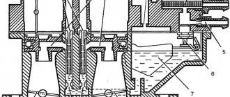
The principle of carburetion is based on the supply of fuel due to the vacuum created by the pistons of an atmospheric gasoline engine. Dosage is carried out by jets - parts with calibrated holes built inside the channels and capable of passing a certain amount of air and gasoline.
Carburetion is based on mixing air with gasoline under the influence of vacuum from the engine
The operation of the DAAZ 2105 carburetor begins with a cold start:
- The air supply is shut off by a damper (the driver pulls the choke lever), and the throttle of the primary chamber is slightly opened by a telescopic rod.
- The engine draws the richest mixture from the float chamber through the main fuel jet and small diffuser, and then starts.
- To prevent the engine from “choking” with a large amount of gasoline, the starting system membrane is triggered by the vacuum, slightly opening the air damper of the primary chamber.
- After the engine warms up, the driver pushes the choke lever, and the idle speed system (IAC) begins to supply the fuel mixture to the cylinders.
The starter choke closes the chamber until the engine starts.
On a car with a working power unit and carburetor, a cold start is performed without pressing the gas pedal with the choke lever fully extended.
At idle speed, the throttles of both chambers are tightly closed. The combustible mixture is sucked through a hole in the wall of the primary chamber, where the CXX channel exits. An important point: in addition to the dosing jets, inside this channel there are quantity and quality adjusting screws. Please note: these controls do not affect the operation of the main metering system, which operates when the gas pedal is pressed.
When idling, fuel enters through the lower hole located under the throttle
The further algorithm of the carburetor operation looks like this:
- After pressing the accelerator pedal, the throttle of the primary chamber opens. The engine begins to suck in fuel through a small diffuser and main jets. Note: The CXX is not turned off, it continues to operate in conjunction with the main fuel supply.
- When you sharply press the gas, the accelerator pump membrane is activated, injecting a portion of gasoline through the nozzle nozzle and the open throttle directly into the manifold. This eliminates “dips” in the process of accelerating the car.
- A further increase in crankshaft speed causes an increase in the vacuum in the manifold. The force of the vacuum begins to draw in a large membrane, which opens the secondary chamber with traction. The second diffuser with its own pair of jets comes into operation.
- When both dampers are fully open and the engine does not have enough fuel to develop maximum power, gasoline begins to be sucked directly from the float chamber through the econostat tube.
When the throttle is opened, the fuel emulsion enters the manifold through the idle channels and through the main diffuser
To prevent a “failure” from occurring when the secondary damper opens, a transition system is used in the carburetor. It is identical in structure to the CXX and is located on the other side of the unit. Only a small hole for fuel supply is made above the closed throttle valve of the secondary chamber.
This is interesting: How to charge a maintenance-free car battery - there is nothing complicated!
Ozone carburetor repair and adjustment
Pavel [therock9618]
24.03.2021,
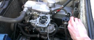
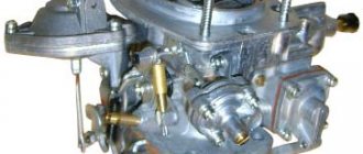
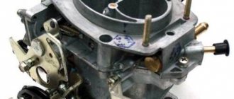
Hello! It's time to get acquainted with the second generation of DAAZ carburetors - "Ozone", which is quite often found on VAZ cars of the classic model. In the last article, I explained the repair and adjustment of the Weber carburetor and I want to say that Ozone is almost the same Weber, with the exception of some innovations, namely: a pneumatic drive of the secondary chamber throttle valve and a modified idle system. Go!
When you are convinced that the carburetor needs to be completely cleaned, it should be removed from the car. To do this, first remove the air filter housing, the hose going to the vacuum brake booster (if there is one), the vacuum ignition timing regulator drive hose, the crankcase ventilation hose and the fuel hose. If you have gas equipment, there is a special spacer for Ozone with throttle valves and connections for gas pipes - disconnect them.
Also, if you have EPHH (forced idle economizer), remove the terminal from the valve. Disconnect the choke cable by loosening the mounting screw and the rod end locking screw. The throttle valve drive is removed using a slotted screwdriver - you need to pry and remove the rod from the drive lever hinge.
Using a 13 mm spanner, unscrew the 4 nuts securing the carburetor to the intake manifold. If you use a regular open-end wrench, you will not be able to unscrew the nut under the accelerator pump, since the body of the wrench will interfere with it, so use a spanner. If you don’t have one at hand, you will have to remove the accelerator pump cover by unscrewing the 4 bolts with a Phillips screwdriver.
Having removed the carburetor from the car, we proceed to its complete disassembly. First, remove the cover by unscrewing 5 screws with a Phillips screwdriver and removing the telescopic rod. To do this, squeeze the rod and remove it from the groove of the three-arm lever.
Using a thin nail, carefully knock out the float axis, remove the float, along with the needle and carburetor cover gasket. Check the float for leaks by lowering it into a container of gasoline. If it sinks, replace it, as the fuel level will be incorrect and the engine will begin to work poorly, as it will begin to “flood”.
Using a 10mm wrench, unscrew the needle valve body - there is an O-ring on it. Using a 19mm wrench, unscrew the fuel filter plug and remove the filter mesh.
Let's disassemble the starting device. Unscrew the 3 bolts securing the starter cover and remove it along with the diaphragm and return spring. Then unscrew the 2 bolts of the starter housing and remove it with the sealing ring of the vacuum supply channel.
In order not to get confused in the future by disassembling everything, let's immediately assemble and prepare the carburetor cover for installation. Using a carburetor cleaner, thoroughly wash the cover and blow with compressed air, remembering to blow through all channels. I recommend replacing the fuel filter mesh with a new one, since the quality of the fuel leaves much to be desired and requires high-quality fine cleaning. Screw on the filter plug. Screw the needle valve body with the O-ring and install a new gasket.
Reinstall the needle and float by hammering the axle. To check the tightness of the needle valve, create a vacuum using your mouth on the fuel supply fitting. The float should be raised as high as possible. A normally closed valve will not allow vacuum to pass through. If the needle is leaking, replace it.
Position the lid vertically and using a 6-7 mm drill, measure the distance from the float to the lid. If it is more or less than required, correct it by bending the float bracket. Thus, we achieve a failed fuel level. If there is a lot of it or, on the contrary, not enough, the engine may work unstably and be difficult to start.
It is also a good idea to check the full stroke of the float. To do this, place the lid in a vertical position and move the float away from it as far as possible. This distance should be 15 mm.
Inspect the trigger diaphragm for cracks. A damaged diaphragm should be replaced. In any case, I advise that when completely disassembling the carburetor, replace all gaskets, diaphragms and o-rings. Lightly sand the starter cover with fine sandpaper placed on a flat surface to achieve a flat surface of the cover and eliminate air leaks. Assemble the starter, but do not screw it to the carburetor yet. Pull the diaphragm rod out as far as possible and, using your mouth, draw air toward you through the hole in the trigger body. After this, release the rod. With a sealed diaphragm and a flat lid, the rod should remain extended, and when you remove the vacuum with your mouth, the rod will return back under the influence of the spring. Now screw the starter housing to the carburetor. The cover is finished and ready to install.
Let's move on to the body. First, remove the bottom cover by unscrewing the 2 fastening bolts from below and disconnecting the end of the pneumatic actuator rod, by removing the lock washer from the end of the rod, unscrew the 2 bolts securing the pneumatic actuator housing and remove the pneumatic actuator itself.
Checking the pneumatic drive. To check, squeeze the stem and draw air through your mouth through the hole in the body. Just like with the starter, when released the rod should remain in the retracted position, and then when you stop drawing air, the rod will return. Otherwise, you need to replace the diaphragm and, just in case, sand the cover with sandpaper. The pneumatic drive is disassembled by unscrewing 3 screws in the cover. Inside there is a spring and a diaphragm with a rod.
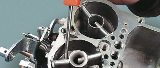
In the housing you need to unscrew 2 fuel, 2 air jets, the jet together with the accelerator pump nozzle, remove the emulsion tubes and diffusers. To remove the emulsion tube, carefully drive a drill of a suitable diameter or self-tapping screw into it and remove it. The diffusers are lifted upwards by slightly prying them with a screwdriver or pliers. The main thing is not to confuse the jet ratings when assembling. Later I will attach a photo with a table of jets. The jets themselves are unscrewed with a slotted screwdriver.
From the carburetor body on the accelerator pump side, unscrew the idle air system nozzle, which is pressed with a holder (plug) under a slotted screwdriver or a solenoid valve, if you have an EPHH. The valve is unscrewed with a 13 key.
On the back of the housing, unscrew the plug along with the nozzle for the secondary chamber transition system.
The accelerator pump cover is secured with 4 screws. Inside is a diaphragm with a return spring. There is a cap screw on top, under which there is a bypass jet - you only need to unscrew the cap screw.
Now the carburetor body needs to be washed, blown and the flange flatness checked. I have already said more than once that the crooked flange is a sore spot of the carburetor, since the wall is very thin, and when tightening the nuts securing the carburetor to the manifold, they are very overzealous and simply bend the flange by tightening it too hard. This is not due to temperature changes, but rather due to strong puffing. To check, you will need glass or a straight metal ruler. Place it on the flange and look at the light. In 99% of cases, a crooked flange and additional gaskets will no longer help, and tightness in this place is very important, since there is an idle passage between the body and the bottom cover.
If the curvature is very slight, you can carefully sand the plane, first removing the protruding tubes from it so as not to spoil them, because fuel flows through them. Do not be afraid that after grinding the flange wall will be thin, the mixture formation will not be the same, etc. - this is not true! =) But yes, the flange will be thinner, but now you know that you can’t overtighten the nuts, so don’t worry. If you still don’t want to use this method, then level it using a press. By the way, this method is the only one in the case when the plane is too curved. The carburetor body at the flange should be heated well with a torch so that the metal yields better and then placed under a press or homemade cleats. Let's return to the components of the case. Check each jet to ensure it is rated using a suitable drill bit. Check all jets and tubes for clearance so that they are not clogged! Screw back the jets and sprayer. The main thing is not to confuse them! Jets should be selected in accordance with the factory table. On the body there is a marking of the carburetor model, according to which you find your model in the table and select the jets. Their number can be seen under a magnifying glass. But usually, what jets you should pay attention to are the fuel, air and idle jets. Basically, they install idle jet 50, fuel jets 112 (primary chamber) and 150 (secondary), air jets 170 (primary) and 170 (secondary).
Also wash, blow out the emulsion tubes and check that the channels are clean. Diffusers have channels that spray the fuel mixture into the cylinders - they need to be cleaned. It is also important to check the tightness of the diffusers to the channels in the housing. Sand the surface of the diffusers using sandpaper for prevention. The pressing force of the diffuser is provided by a wire spring on the reverse side. You can pull it out and try to bend it. Over time, the spring gets tired and bending is not enough, so you can gently tap the sides of the diffusers with a hammer to flatten them a little. This will help the diffusers fit tightly, the main thing is not to overdo it.
All that remains is to screw in the jets and put back the emulsion tubes and diffusers. Check that the secondary chamber adapter nozzle plug is screwed in all the way. Do the same with the idle jet plug. If you have an EPHH valve instead of a plug, then very carefully tighten it with a 13mm wrench, otherwise it will not work properly.
Inspect the accelerator diaphragm for cracks and replace if necessary. The accelerator pump cover is sanded with sandpaper and when screwing it on, I advise you to keep the diaphragm drive lever raised up. With this action, maximum filling of the accelerator pump is achieved.
We're done with the body for now. The bottom cover consists of 2 axes with throttle valves of the primary and secondary chambers, damper drive levers, idle channels and idle speed adjustment screws. Carefully shake both throttle valves and check for play; if there is any, tighten the 2 bolts securing the valve to the axle.
To check the damper drive mechanism, twist the levers of the primary and secondary chambers, opening them to the maximum position. And remember, since the secondary chamber has a pneumatic drive, the secondary chamber damper lever will open only when the primary chamber damper is open at least 50% (plus or minus), since when the primary chamber damper is closed, its lever blocks the secondary damper lever.
When rotating the damper drive levers, they should open without effort and clearly return to their original position under the influence of springs. If you feel a slight jamming, fill the levers with WD-40 and rotate them to open and close, possibly dirt has got there, and then blow with air. Otherwise, you will have to disassemble the levers and clean everything manually. The main thing is to collect everything the same way it was. To do this, use the photo that I will attach below. If necessary, after disassembling the damper drive mechanism, you can remove the axles and clean them together with the dampers. But the axles very rarely turn sour, and usually it is enough to clean the valves without disassembling anything.
On the side of the bottom cover there are 2 idle speed adjustment screws: the large one is the quality screw, and the smaller one is the quantity screw. You need to unscrew them and check the condition of the O-rings - they should be intact and elastic. But it's better to replace it right away.
Inside the channel where the quantity screw is screwed in, there is a sprayer. On older carburetors, it is a wide double ring with holes in a circle, and on younger ones it is an ordinary ring. A half-ring sprayer is much more convenient and reliable, since it does not have such thin holes that clog very quickly. The sprayer itself is pressed inside, and to remove it you will need a special device that you can make yourself.
Or you will have to clean it on the spot with a needle, soak it in a cleaning agent for a long time, which is very inconvenient, especially with the sprayer of old releases - there are too many holes and each one needs to be cleaned. Sometimes you can’t get to it with a needle, and then use one short strand of stranded wire.
The body has been completely disassembled and is now ready for washing and cleaning. I advise you to pay attention to its flatness on both sides, since if the fastening to the manifold is tightly tightened, the bottom cover will also “lead.” Reassemble everything in reverse order. Don't forget to also clean the idle speed adjustment screws and passages. I would like to draw your attention to the fact that, unlike Weber, Ozone has both valves closed at idle, and under the primary chamber valve there is an idle hole that supplies fuel to the engine. It must be clean!
After assembling the bottom cover, you should adjust the position of the flaps. Point the lid to the light and look at the flaps. They should not allow light to pass through them. But at the same time I want to pay attention to how they lie. At each damper, a drive tab extends from the side of the carburetor, which rests on the screw. By rotating it, you can adjust the stop or, in other words, the clearance of the dampers.
By tightening the stop screw of each shutter little by little, find the position when it barely begins to let in light, and then turn the screw little by little until this gap disappears. This is done so that the damper rests clearly against the adjusting screw, and not against the wall of the channel, otherwise over time, when you press the gas, a hole will form in this place, which will allow excess air to pass through when the damper is normally closed.
This completes the cleaning and preparation of carburetor parts. Let's move on to assembly and configuration. Screw the bottom cover to the body with two screws and install new gaskets between them. Let me remind you that there is one thermal insulation pad and one cardboard pad on each side. Let's start setting up the accelerator pump. Pour gasoline into the float chamber in accordance with the regulated fuel level. The level should be in the middle of the float chamber casting. By turning the primary chamber flap drive lever, on the reverse side of the axis, the protrusion runs onto the accelerator pump rod and compresses the diaphragm, supplying a large portion of gasoline under pressure into the engine through the nozzle nozzle. First, the diaphragm needs to fill the cavity, since there is no fuel in it. Then the sprayer will start spraying. At this time, pay attention to the stream from the sprayer - it should be uniform and without smudges. If there is a discrepancy, clean the nozzle of the sprayer again with a thin strand of wire and blow it with air. Also, the spray jet should “hit” directly on the collector, that is, not on the diffuser, not on the chamber wall, not on the damper, but precisely on the collector. If the stream “hits” past, you can carefully bend the spout and check everything again until you achieve what I said above. Now let's check the performance of the accelerator pump. Pour gasoline into the float chamber at the correct level, place the carburetor over a clean container and turn the throttle lever, give 10 injections with the accelerator pump. Draw gasoline from this container into a 10 cc syringe. With normal accelerator pump performance, you should get 7-8 cubic meters of gasoline. If there is a discrepancy with the specified volume, and also if the accelerator pump does not supply fuel at all or supplies it very poorly, check the discharge valve located in the spray nozzle. If the ball “sours,” the pump may not work at all. Everything can be solved by soaking in a cleanser and blowing with air. If the valve is working properly, you can hear the ball dangling if you shake it.
Also check the supply channels inside the pump - unscrew the accelerator pump cap, pour gasoline into the float chamber and turn the throttle lever. There should be visible streams of fuel with a characteristic bubbling sound coming through the bypass holes. If necessary, clean and blow out. Clean the accelerator pump bypass jet with carb cleaner by unscrewing the plug screw above the pump housing.
The body is ready. Screw on the carburetor cover, tightening the bolts crosswise to evenly distribute the gasket. I don’t see the point in pulling too hard, since after installing the carburetor on the car, you will check the fuel level in the float chamber and for this you will need to remove the cover again. Reinstall the telescopic rod. On Ozone carburetors there is often a telescopic rod or a closed-type “telescope”. This type of traction is unreliable, since dirt gets inside the moving elements and they stop working. Hence the poor start of the engine and it didn’t last long the first time. I advise you to install an open telescope to forget about this problem.
Let's set up the launcher. The principle of its operation is that you pull out the “choke”, which is connected by a cable to the air damper lever, which blocks the air channel of the primary chamber. When the engine is rotated by the starter, the engine discharge affects the starter diaphragm, which, through a rod, simultaneously opens the air and throttle valves of the primary chamber to the desired angle, delivering a rich mixture to the engine, which is important during cold starts. Therefore, with the choke extended and the engine running, the speed is about 3 thousand.
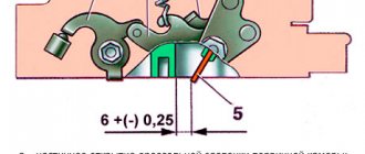
Adjusting the starting device consists of setting the required starting gaps of the dampers. The air damper opens at start-up by 5-5.5 mm, and the throttle by 0.7-0.9 mm. You will need one drill of the appropriate diameter for each flap. To check the current starting clearances, you need to simulate a manual start. To do this, first press the air damper drive lever so that it completely blocks the primary chamber channel, and then press the trigger rod. Now you can see both gaps.
The throttle clearance of the primary chamber is adjusted by bending the rod with pliers - the main thing is not to overdo it. We bent the rod, simulated the starting gaps, checked it with a drill, if it doesn’t match, we bent it again and checked it.
To adjust the air damper gap, in the center of the starter cover, there is a plug for a slotted screwdriver - unscrew it. There is also an adjusting screw inside for the slot, which, when rotated, adjusts the air damper clearance. Rotate it just during the launch simulation to make it easier to monitor changes.
The carburetor is ready to be installed on the car. Replace the gasket between the carburetor and the intake manifold and install the carb in the reverse order of removal. After installation, check that when the choke is pulled out, the air damper completely blocks the primary chamber channel. Also check that when you press the gas pedal all the way, the primary chamber damper is completely open.
Using the manual fuel pump drive, pump fuel into the carburetor. Depending on the pump's performance, I can't say exactly how much you need to pump. I think intensive pumping for one minute should be enough. Remove the carburetor cap and check the fuel level. Since you have already adjusted the correct clearance and float stroke when cleaning the carburetor, now you are checking for correct operation. In theory, the level should be normal, if not, correct it by bending the float bracket with the familiar way. Screw the cap on and this time you can tighten it.
Everything is ready for the first start and idle settings. Make sure that the ignition is working properly and is set correctly, there are good spark plugs with the required gap, and the fuel pump has good performance and its rod output is adjusted. I will devote a separate article to this procedure, but now let’s proceed to setting the idle speed.
If your quantity and quality adjusting screws are not tightened, tighten them all the way. Then unscrew the quantity screw by 1 full turn, and the quality screw by 2. Start the engine. If the engine does not start, unscrew each adjusting screw one more turn.
Your task is to start the engine. Even if it works unstably or at too high speeds, the main thing is to start it and warm it up, since the idle speed needs to be adjusted only when the engine is warm.
Now a little theory. Imagine 2 channels: air and fuel, which converge into one common channel, which exits under the throttle valve of the primary chamber. On each individual channel there is a screw: the amount of mixture in the fuel channel and the mixture quality screw in the air channel. Each screw changes the size of its channel, so when tightened, the patency of the channel becomes lower, and when unscrewed, it is correspondingly higher. It turns out that using screws, you manually adjust the idle mixture.
Once the engine has warmed up, you can begin tuning. To monitor the speed, use the standard tachometer in the dashboard or connected to the ignition coil. We carry out the adjustment in 4 stages:
1) While turning the quality screw clockwise and counterclockwise, listen to how the engine operates. You must catch the moment at which the speed will begin to rise and will be at its maximum possible.
(I will explain this more clearly. So, without touching the speed screw, if you tighten the quality screw all the way, the engine will begin to work unstably, that is, the amount of air that we supply with the quality screw is not enough for the complete combustion of the volume of fuel that we set with the quantity screw . Now, on the contrary, by unscrewing the quality screw, we increase the gap in the air channel and supply more air. At this moment, you can hear how the engine begins to work steadily, and the speed begins to increase - this is the so-called “slide”. When we continue to unscrew the quality screw further, there is more air more than enough and the motor starts to work unstably again. And now your task is to find exactly the “top” of this “slide”, that is, the most optimal position of the quality screw, at which the motor will operate as stable as possible. According to the laws of physics, and in our case this is combustion fuel-air mixture, if the mixture is too rich (more gasoline, less air) and too lean (less gasoline, more air), complete and timely ignition cannot be achieved, and the engine will operate unstably. I emphasize this, since many people believe that unstable operation can only occur with a lean mixture. As you can see, this is far from the case.)
2) By unscrewing the quantity screw, increase the engine speed to approximately 1100 rpm.
3) Rotate the quality screw and find the “top of the hill” at these speeds.
4) Tighten the quality screw from this place (from the “top of the hill”) so that the speed drops to 1000 revolutions.
According to the regulations, they recommend 850-900 rpm, but I advise you to do 1000 rpm, since the engine works well, reacts vigorously to gas and the battery will charge well. That's all. I hope you found it clear and interesting to learn about the maintenance of carburetors of the Ozone family. See you again!
Briefly about the features and structure of the “six” carburetor unit
Before adjusting the carburetor on a VAZ 2106, it doesn’t hurt to know its design features. After 1980, Ozone and Solex began to be installed on Tolyatti cars. The purpose of the unit’s operation is to prepare a combustible mixture before feeding it into the car’s cylinders. Down to the subtleties, this is not a driving school, we will not disassemble the design, it is enough to familiarize yourself with the main components that ensure optimal operation of a carburetor internal combustion engine:
- Fuel dosing system.
- Mechanisms for controlling throttle valves and enriching the mixture.
- Idle system.
- Accelerator pump and econostat.
- Float chamber.
A chamber with a float and a needle valve is responsible for the stability of the fuel level. Next, gasoline, flowing through the spray tube, enters the chamber, where it mixes with air from the inlet pipe. The amount of mixture is adjusted by the throttle valve, which is connected to the accelerator pedal.
Precise adjustment allows you to prepare the correct mixture of gasoline and air in a ratio of 1:15. During long-term operation of the car, the settings get lost and you have to think about how to adjust the carburetor on a VAZ 2106 on your own. The adjustment technology is the same for both Solex and Ozone.
Adjustment and Maintenance
For stable operation of all systems, there are maintenance regulations that must be followed. Before adjusting the ozone carburetor on cars of brand 2107, you need to identify the faulty unit; there is no need to rinse or disassemble working units. Flushing the system can be done easily at home; it is important to follow the sequence of steps.
- Repair and adjustment of the ozone 2107 carburetor begins with its dismantling and disconnecting all supply systems. It is necessary to disconnect the throttle valve actuator, the coolant supply, and the fuel hose.
- Clean and rinse the VAZ carburetor, modify the outside with ozone, and inspect for mechanical damage.
- Clean the strainer and starter with compressed air under low pressure.
- The float system is cleaned of obvious carbon and deposits. It is important to understand that old scale will be difficult to clean, and it can also get into the nozzle holes and disrupt the operation of the system.
- Wash and adjust the trigger mechanism, air jets, and exhaust system.
- We adjust the carburetor components, assemble and install the device before regulation, which is subsequently adjusted to a hot engine.
Adjustment and tuning are carried out according to the assigned sequence of screws, for the desired fuel consumption and dynamic performance of the car. The technical condition fully corresponds to the driving characteristics and comfort when moving the vehicle.
Ozone carburetor jets table
| Carburetor markings | Main system fuel jet | Main system air jet | Idle fuel jet | Idle air jet | Accelerator pump jet | |||||
| I Kam. | II Kam. | I Kam. | II Kam. | I Kam. | II Kam. | I Kam. | II Kam. | fuel | bypass | |
| 2101-1107010 | 135 | 135 | 170 | 190 | 45 | 60 | 180 | 70 | 40 | 40 |
| 2101-1107010-02 | 130 | 130 | 150 | 190 | 50 | 45 | 170 | 170 | 40 | 40 |
| 2101-1107010-03: 2101-1107010-30 | 130 | 130 | 150 | 200 | 45 | 60 | 170 | 70 | 40 | 40 |
| 2103-1107010 | 135 | 140 | 170 | 190 | 50 | 80 | 170 | 70 | 50 | 40 |
| 2103-1107010-01: 2106-1107010 | 130 | 140 | 150 | 150 | 45 | 60 | 170 | 70 | 40 | 40 |
| 2105-1107010-10 | 109 | 162 | 170 | 170 | 50 | 60 | 170 | 70 | 40 | 40 |
| 2105-1107010: 2105-1107010; 2105-1107010-20 | 107 | 162 | 170 | 170 | 50 | 60 | 170 | 70 | 40 | 40 |
| 2107-1107010: 2107-1107010-20 | 112 | 150 | 150 | 150 | 50 | 60 | 170 | 70 | 40 | 40 |
| 2107-1107010-10 | 125 | 150 | 190 | 150 | 50 | 60 | 170 | 70 | 40 | 40 |
| 2108-1107010 | 97,5 | 97,5 | 165 | 125 | 42=3 | 50 | 170 | 120 | 35/40 | — |
↑
Video - How to set up a VAZ 2105 carburetor
Useful tips
- Valve position . It must be pushed in so that the idle jet touches its connector (seat) in the device body. To do this, it is recommended to lubricate the rubber seal with engine oil.
- The position of the air damper of the cold pass system , with the choke handle lowered, must be in a strictly vertical plane.
- When the quality adjustment screw is screwed in all the way, the engine should stall . If this does not happen, the reason may be incorrect adjustment of the VAZ-2105 carburetor. Using the appropriate bolts, you need to change the speed up.
- Vacuum in the tube between the carburetor and the ignition distributor. When the engine is idling, there should be no vacuum in the vacuum tube. The reason for its occurrence may be a tightly tightened locking screw of the throttle valve. Adjustment of this element is carried out using a locking screw. In the correct position, the damper does not jam in the diffuser and provides sufficient tightness. When pouring into the chamber 2-3 cm
3fuel, it should not noticeably leak through the valve. When you press the gas pedal, it moves smoothly without jerking. An identical method is used to test and adjust the damper on the second chamber, with the exception of the tube, which is only in the first chamber.
- Solenoid valve. In carburetors designed for engines with a displacement of 1500 cm3 or more
3, in place of the holder of a conventional fuel jet there may be an electromagnetic valve with an XX jet. If it is included in the design of the device in question, it is necessary to check its functionality and ensure the integrity of the electromechanical element. With the ignition on, you need to remove and put the connector on the valve. The occurrence of clicks during these operations will indicate the serviceability of the part being tested.
- For the summer season, it is recommended to reduce the idle speed to 800-900 units, and in winter to increase it to 900-1000 rpm . This setting will improve the efficiency of the power unit taking into account climatic conditions.
The following problems are also possible:
- Excessive (low) gasoline level in the float chamber.
- The air filter is clogged (here you can save yourself with a regular replacement).
In modern cars with an injection engine and electronic fuel injection, such as the VAZ 2110-2115, no less reasons can be identified. In this case, problems are often associated with the breakdown of one of the sensors.
What happens? The electronic control unit tries to read information and does not receive it. As a result, malfunctions in the operation of the power unit appear, and instability in speed appears.
But let's highlight all the main reasons. There are several of them:
- Problems with spark plugs (poor quality, wear, contamination);
- interruptions in the air supply (failure of the mass air flow sensor);
- air intake from outside into the intake system;
- damage (defect) of high-voltage wires;
- failure of the XX regulator;
- EGR sensor malfunction.
When the idle speed is floating, the first thing to do is check the idle speed control. Most often it is located next to another sensor that controls the throttle position. Checking is carried out using a multimeter.
If the sensor resistance is outside the normal range (40-80 Ohms), then there is a high probability of IAC failure.
If everything is normal with the idle speed control, you can move on to the next “suspect” - the mass air flow sensor.
To check the device, you need to disconnect the connector from it and start the engine. In this case, the engine speed will be around 1,500 rpm. If the dynamics only improve while driving, then the mass air flow sensor is really faulty.
The EGR valve is responsible for the movement of exhaust gases. The sensor's task is to return some of the gases back to the combustion chamber. This is necessary to ensure complete combustion of fuel and minimal harm from exhaust gases. Cleaning the valve seat is often enough to fix the problem.
3. In diesel cars, the cause of floating idle speed may be the appearance of corrosion on the moving blades in the power pump. As a result, they simply jam and stop coping with their function.
To prevent this from happening, you need to add at least a little motor oil to the fuel tank (200-250 grams is enough). This is enough to protect the metal elements with a thin layer of oil.
Now floating idle speeds will not cause you to panic, because you know what causes them and what needs to be done. Good luck on the roads and of course no breakdowns.
Adjustment instructions
To set up a cleaned and functional carburetor, you should prepare the following tool:
- short flat screwdrivers with narrow and wide slots;
- open-end wrench size 10 mm;
- the same, size 8 mm;
- narrow pliers.
The primary adjustment consists of adjusting the trigger cable and the gas pedal linkage. The latter is easily adjusted: the plastic tip is positioned opposite the hinge on the carburetor axis by twisting it along the thread. Fixation is carried out with a nut for a 10 mm wrench size.
The cable housing is attached with the air damper fully open.
The choke cable is adjusted as follows:
- Push the lever in the cabin all the way, set the air damper in a vertical position.
- Pass the cable through the eye of the cover and insert the end into the hole in the latch.
- Hold the barrel with pliers and tighten the bolt with a wrench.
- By moving the choke lever, make sure that the damper opens and closes completely.
The next step is to check the opening of the secondary chamber throttle. The stroke of the membrane and the rod should be enough for the damper to open 90°, otherwise unscrew the nut on the rod and adjust its length.
To shorten or lengthen the drive rod, you need to loosen the fixing nut
It is important to clearly align the throttle valve support screws - they must support the levers when closed. The goal is to avoid friction between the edge of the shutter and the chamber wall. It is not permissible to adjust the idle speed using the support screw.
The support screw heads are fixed at the factory using special paint
The accelerator pump does not require additional adjustment. Make sure that the lever wheel is adjacent to the rotating sector, and the end is adjacent to the “heel” of the membrane. If you want to improve acceleration dynamics, replace the standard nozzle marked “40” with an enlarged one “50”.
The idle speed is adjusted in the following order:
- Turn out the quality screw by 3-3.5 turns, the quantity screw by 6-7 turns. Using the starter, start the engine. If the crankshaft speed is too high, reduce it with the quantity screw.
- Let the engine warm up, remove the choke and adjust the crankshaft speed to 900 rpm using the quantitative screw, using the tachometer as a guide.
- After 5 minutes, turn off the engine and check the condition of the spark plug electrodes. If there is no soot, the adjustment is complete.
- If black deposits appear on the spark plug, clean the electrodes, start the engine and tighten the quality screw 0.5-1 turn.
Set the tachometer reading to 900 rpm using the second screw. Let the engine run and check the spark plugs again. Adjusting screws control the supply of the fuel mixture at idle
The best way to set up a DAAZ 2105 carburetor is to connect a gas analyzer to the exhaust pipe that measures the CO level. To achieve optimal gasoline consumption, you need to achieve readings of 0.7-1.2 at idle and 0.8-2 at 2000 rpm. Remember, the adjusting screws do not affect gasoline consumption at high crankshaft speeds. If the gas analyzer readings exceed 2 CO units, then the size of the fuel nozzle of the primary chamber should be reduced.
Ozone carburetors of the DAAZ 2105 model are considered relatively easy to repair and adjust. The main problem is the considerable age of these units, produced since the times of the USSR. Some copies have reached the required service life, as evidenced by large play in the throttle valve axles. Severely worn carburetors cannot be adjusted, so they have to be replaced entirely.
Idling
The DAAZ-2105 1107010 carburetor is adjusted as follows. The mixture toxicity screw must be unscrewed approximately 3.5 turns. The quantity screw is unscrewed 7 turns. Using a starting device, the power unit is started. If the speed is high, you can reduce it by tightening the quantity screw. The engine needs to be warmed up.
Next, remove the choke completely and adjust it using a screw to approximately 900 revolutions. After this, turn the quality screw. They twist it and achieve the highest speeds. You need to find the position at which the speed will be maximum. This is the correct position. With this position of the screw, the fuel burns as efficiently as possible and the idle speed is smooth. And if you rotate it further, the engine will become unstable.
Many people recommend adjusting the idle speed of the DAAZ-2105-20 carburetor using spark plugs. When the engine is idling, regardless of the quality of the mixture, the spark plugs will be black, so you should not trust this method.
Why does the cylinders flood?
Also look carefully at the spark plugs; if they have heavy carbon deposits on them, the engine will run unstably. But if a lot of gasoline enters the combustion chambers, then most likely it is necessary to adjust the level in the float chamber. How to adjust the level will be discussed a little below. The saddest thing is if the reason that the cylinders are flooded is a burnt out valve.
In this case, the cylinder head will have to be repaired. If the engine runs unstable, as well as stops at high speeds, look for a fault first of all not in the carburetor, but in the fuel pump and its drive. But you need to look at the carburetor of the VAZ 2105; adjustment will not hurt it.
What malfunctions can occur in the carburetor?
It is worth noting that many problems in the carburetor are very similar in their symptoms to those that appear when the fuel supply and ignition systems break down. For example, if an internal combustion engine operates unstably, the speed constantly fluctuates, and sometimes it even begins to stall, then you should not immediately blame the carburetor directly. Most likely, the reason for this behavior lies in the fuel supply system to the carburetor.
Very often the electric valve, which is mounted in the housing, fails. Its winding may burn out, which is why the fuel supply from the fuel pump does not occur. Therefore, before you start adjusting the carburetor, you need to make sure that the electric valve is working normally, its winding is intact, and the jet is not clogged. But for all other troubles, you can blame the carburetor of the VAZ 2105 - its settings are most likely out of order.
Preliminary stage
Before you properly adjust the carburetor on a VAZ 2106 with your own hands , it is important to carry out a number of work steps:
- Adjust the thermal clearances of the gas distribution mechanism.
- Set the optimal ignition timing.
- Open the air damper completely.
All work on setting up the carburetor unit is carried out on a warm engine. Do not forget that during the process you may need new parts and rubber products, so it is better to purchase a repair kit in advance.
DIY repair
If you want to overhaul the engine yourself, pay special attention to the marks, which are needed even for ordinary simple operations, such as adjusting valves. Marks also allow you to correctly install certain parts and components.
A diagram or a detailed video, which you will find at the end of the article, will help you in your work. Regardless of the simple device, the VAZ 21053 engine must be assembled as accurately as possible. Of course, the engine should be repaired on a clean workbench so that particles that accelerate wear do not penetrate inside.
Remember that in some cases the markings are applied to the parts incorrectly, so even if the marks are compared, unstable operation of the unit may be observed. In this case, the part should be replaced or contacted by specialists with high-quality diagnostic equipment. You can always consult with experienced owners of VAZ 21053 cars, who should know the structure and features of repair work.
Main parts
To perform its tasks, the carburetor
VAZ 2105 consists of the following mechanisms and systems:
See:
- Engine starting and warming up system.
- System for maintaining the required fuel level .
- System XX (idle);
- Econostat system.
- Acceleration pump.
- Main dosing system.
There are three systems that can be configured - they are first on the list. Adjusting the VAZ carburetor 2105
can be performed without removing the device from the machine. How to adjust the carburetor on a UAZ. Due to the fact that the carburetors of the fifth and seventh models are identical in structure and differ only in the diameters of the holes of the air and fuel jets, the carburetor for the VAZ 2107 can be adjusted using the same method.
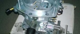
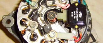
Device
In the design of the DAAZ-2105 carburetor, three main parts can be distinguished. This is the cover, the main block, and also the housing in which the throttle valves are located.
There is a built-in starting system installed in the carburetor cover - it is semi-automatic. The lid also contains a fine fuel filter, a needle valve and a float, and an econostat tube. The top cover is secured to the middle part of the carburetor using five screws.
The main part has a more complex structure. There is a float chamber for fuel, and the main metering system is built here, consisting of air and fuel jets and diffusers - large and small. In the middle part there is also a diaphragm accelerator pump with a ball valve, channels for powering the transition system and idle channels. In the middle part there is a vacuum drive for the throttle valve of the second chamber.
At the bottom of the DAAZ-2105 carburetor there are damper axles, as well as screws for adjusting the operation. These are the screws of mixture quantity and toxicity. In addition, the lower block has a lot of channels for the operation of the idle system, transition and starting systems. The lower part of the carburetor is attached to the middle main part with screws.
Expert advice
After completing the procedure for adjusting the VAZ-2105 carburetor device, experienced auto mechanics recommend paying attention to the following critical points:
- Valve location - is in the retracted position, with the idle speed jet touching the seat in the carburetor body.
- Lubricating the rubber seal with special motor oil.
- The location of the air damper intended for cold passage is in a vertical plane, while the suction handle is lowered.
- The condition of the solenoid valve - the presence of damage and malfunctions is checked as follows: turn on the ignition;
If clicks are heard during the inspection process, the part is in full working order.
How to clean the carburetor on a moped - step-by-step instructions
Cleaning is necessary if a lot of dirt and condensation has accumulated. To ensure that this procedure is not necessary, it is advisable to disconnect and disassemble the carburetor. If it is clogged, it is useless to perform adjustments.
First, turn off the fuel supply valve, then you need to disconnect the fuel and drain hoses from the carburetor.
Next, you need to disconnect the inlet pipe from the carburetor, then unscrew the throttle valve cover and remove it from the carburetor. Now the part is held in place only by two bolts, which can be unscrewed with a 10mm wrench. That’s it, the carburetor has been removed. It is advisable to disassemble it on a white table so as not to lose small parts.
Next you need to disassemble the carburetor. First, unscrew the bolts located on the carburetor body. After this, the protective cover will be removed.
Next, the float chamber is pulled out; it is held on one pin, which is removed from the grooves. It can be removed without using tools. Together with the camera, a small cylindrical part with a cone-shaped tip will be removed - a shut-off needle, which is held between the float and the fuel supply channel
It is important to ensure that it does not fall on the floor and get lost.
Now, using a screwdriver with a straight bit, unscrew the jets, the idle speed adjustment bolt and the mixture quality screw.
The unit is disassembled, you can proceed to cleaning. First, attach the tube attachment to the aerosol canister for cleaning.
The accumulated liquid is poured out of the carburetor cap, then the internal cavity is treated with a cleaning aerosol. The jets are treated in the same way; the aerosol tube can be lowered into the recesses and holes. Then all the internal cavities will be cleaned, and all the accumulated dirt will come out. An aerosol with a nozzle can be used to treat all other carburetor openings.
Small holes need to be blown out so that there is no dirt there.
The cleaned parts are wiped dry with a cloth; it is important to wait until the applied aerosol has completely dried. Then assemble the carburetor in reverse order
It is difficult to make a mistake during assembly, since all the parts differ in size and are placed only in certain holes.
Disassembled carburetor of an Alpha moped
When installing a float chamber, first attach an element that shuts off the fuel supply through the hole near the jets. A pin is connected to the camera mount, after which the entire structure is placed on the socket. Next, the cover is mounted and the bolts are tightened. Tighten the mixture quality screw one and a half turns, then tighten the idle speed screw.
It is recommended to spray the assembled carburetor to keep it clean on the outside. Next, the part is put in its original place, first the fuel hose is connected. Then you need to open the fuel valve and wait a few seconds until the fuel fills. You can now start the engine, but it may not start or may be too loud. This means that adjustment is necessary.
You can learn more about how to clean the carburetor on an Alpha moped from this useful video:
Setting the needle valve opening
Turn the carburetor cap over so that it is positioned vertically. In this case, the tail of the float should lightly touch the needle ball. Please note that even partial overlap is not allowed. Measure the distance using a paper template. Determine the distance from the plane of the float to the gasket on the carburetor cover. It should be no more than 6.5 mm. If it is larger or smaller, then adjust in the desired direction by bending the small tail on the float. The distance to the maximum degree of valve opening is measured in the same way.