Auto gearbox 2109
The speed of the car is selected by a mechanism called a gearbox. The VAZ 2109 car is equipped with five or four gearbox stages. Timely diagnostics of the operation of the unit, repair and replacement of worn parts with new ones yourself ensures reliable operation of the car. The cost of repairs will be significantly lower than if you involve car service specialists. The VAZ 2109 gearbox requires repair in the following cases:
- If the elements of the assembly heat up.
- There is increased noise when the engine is running.
- Cannot change gears
- While driving, the transmission may get knocked out.
Repair of VAZ 2109 gearbox
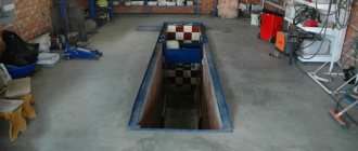
Before starting repair work, the gearbox is removed from the vehicle. To do this, the car is placed on an inspection hole or a lift, and the hood is secured against accidental closure. So:
- The battery, TDC sensor, and starter traction relay are disconnected.
- The ground wire is disconnected from the crankcase.
- The TDC sensor and the clutch housing are separated from each other.
- The speedometer turns off.
- The clutch release fork is disconnected.
- To lift the engine, a bracket is mounted to the stud that secures the exhaust manifold.
- The motor is suspended from the lifting mechanism.
- The engine splash guard and the cover located at the bottom of the clutch housing are removed.
- The oil is drained from the gearbox.
- The reverse light turns off.
- Its rod is disconnected from the gear selection rod.
- The engine and gearbox are separated.
- The steering knuckle hub axle shaft is released from fixation.
- The ball joints located on the suspension arms are disconnected from the knuckles.
- The shafts for wheel drives are retracted to the sides.
Tip: If the wheel drive and side gear are difficult to separate, it is necessary to simultaneously remove the gearbox and the wheel drive, and then press out the hinge on the bench plate.
- The gearbox is removed from the studs and the suspension bracket located in the eyes of the machine body spar is removed.
- The starter is removed.
- The clutch driven disc and the gearbox shaft, which secures the crankcase to the engine, are disconnected.
- The gearbox is removed from the car.
Advice: When repairing the gearbox, you need to pay attention so that its input shaft does not rest on the petals located on the pressure spring. This may damage them.
Gearbox disassembly
Repairing the VAZ 2109 five-speed gearbox begins with cleaning it of dirt and a good wash of the outside. So:
- The box is placed vertically up. The nuts securing the rear cover of the unit are unscrewed.
- The clutch cable bracket is removed.
- Using a rubber hammer, carefully remove the rear cover from the gearbox housing.
- The sealing gasket is removed.
Tip: If the gasket is removed carefully and is not damaged, it can be reinstalled during reassembly.
- Third or fourth gear is engaged.
- The bolt securing the fifth gear fork is unscrewed, which is then engaged. In this case, the synchronizer clutch moves down along with the fork so that the coupling splines engage with the gear.
- It is necessary to make sure that the shafts do not rotate.
- The nuts on the primary and secondary shafts of the gearbox are unscrewed.
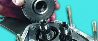
- Use a screwdriver to pry up and remove the fifth gear synchronizer along with the fork.
- The fork is removed from the coupling.
Tip: Removal of the synchronizer must be done carefully. The synchronizer clutch must not be allowed to come off the hub. Otherwise, the spring-loaded balls that secure the synchronizer may fall apart.
- The ring blocking fifth gear is removed from the synchronizer.
- Using a screwdriver, pry the fifth gear driven gear and remove it from the secondary shaft.
- The thrust ring is pulled out from the needle bearing.
- The needle bearing for the fifth gear is removed.
- The drive gear of the same transmission is removed from the input shaft.
- The bearing plate is released from the fastening and removed.
- The fifth gear needle bearing bushing and thrust washer are removed from the output shaft.
- The bearings of the primary and secondary shafts are freed from the retaining rings.
- The locking plug is unscrewed.
- Carefully remove the retainer balls with the spring.
- The rear engine mount is removed, which is first freed from the mounting bolts.
- The reverse lock plug is unscrewed. Then the gearbox is tilted and the locking ball is removed from it along with the spring.
- The nuts and bolt securing the gearbox housing to the clutch housing are unscrewed.
- Using a large screwdriver, the gearbox and clutch housing are separated.
Tip: In order not to damage the gasket for sealing, a screwdriver is inserted into special grooves and gently rocked until the components are separated.
- The gearbox housing is removed.
- The fork for shifting the first two gears is released from its fastening, the rod is lifted and removed together with the fork from the assembly.
- The bolt securing the fork is unscrewed to change third and fourth gears.
- The connecting rod head is disengaged from the mating part and the rod is removed simultaneously with the fork.
- The head of the fifth gear rod is removed from the lever, which is then turned and pulled out.
- The retaining ring is removed.
- The fork is removed to engage reverse gear.
Removing the fork to engage reverse gear
- The reverse gear is removed along with the axle.
- At the same time, the shafts - primary and secondary - are removed. To do this, they need to be slightly rocked from side to side.
Pulling out the primary and secondary shafts
- The main drive driven gear is removed along with the differential.
- The gear shift mechanism is released from the mount and removed.
- The sealing gasket is removed.
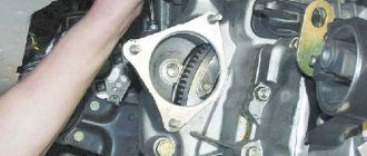
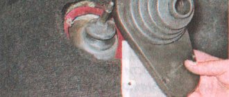
- The front bearing is pressed out of the clutch housing on the secondary shaft into the housing, as shown in the photo. To replace it, you need to remove the oil seal.
Pressing out the front bearing on the clutch housing output shaft
Tip: Replacement of the input shaft bearing must be done with replacement of the oil seal.
- The magnet is pulled out of the clutch housing.
- The nut holding the speedometer drive housing is unscrewed, which is then removed from the driven gear of the unit.
- If necessary, replace the rubber ring on the device body for sealing.
- The speedometer drive housing is freed from the driven gear with the shaft and the sealing ring.
- The switch for the reversing light is unscrewed from the gearbox housing.
- From the flange located on the gearbox, the cover protecting the drive rod joint for gear shifting is moved and the opposite edge of the protective cover is removed from the hinge flange.
- The bolt securing the hinge on the gear shift rod is unscrewed and the hinge is removed from the rod.
- The protective cover is removed.
- The lever and rod are released from the fastening and pulled out from the clutch housing.
- If there are traces of oil leakage on the clutch housing, it is necessary to replace the oil seal on the gear shift rod.
Inspection and troubleshooting of gearbox parts
So:
- The clutch housings and rear gearbox cover are visually inspected. Parts must not have cracks or chips. The mating surfaces are free of marks, dents and nicks. Minor damage can be removed using sandpaper. Severe defects indicate replacement of parts.
- The bearing seats in both crankcases are checked. They must be free of damage and signs of wear.
- The gear shift rods are checked. Seizures, holes in places for clamps, burrs, and bent indicate replacement of the rods.
- The box seal is checked. If there are leaks, replacement is required.
- The gear shift forks are checked. If they are severely worn, they need to be replaced.
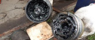
- When bearings wear out, they must be replaced.
- Damaged gaskets are replaced.
- The magnet is cleaned of wear particles. Cracks and weakening of magnetic properties are not allowed.
- The mating surfaces of the gearbox, clutch housings, and rear gearbox cover are thoroughly cleaned of old sealant.
Let's look at typical failures and malfunctions of the Lada Kalina and how to eliminate them
A little history. The Lada Kalina is a budget B-class car. Mass production of this car at the AvtoVAZ plant began in 2004.
In September 2012 The second generation of Lada Kalina was presented at the Moscow car showroom. The second generation included a station wagon and a hatchback. The sedan was released as the Lada Granta model. In March 2013, a modification with a liftback body appeared on the Lada Granta.
Modifications:
- Lada 117 – station wagon (Combi), 1117
- Lada 118 – sedan;
- Lada 119 – hatchback;
- Lada 119 Kalina Sport – hatchback, sports version.
- Lada 118 Granta – sedan, with a liftback body.
Engines:
- 4 l, 16 valves, model 11194 volume 1.4 l., power 98 l. s., torque 120 Nm/3000
- 1.6 l model 21114, 8 valves, model 21114, power 89 hp. With. torque 127 Nm/4200-4800;
- 6 l model 21126, 8 valves, volume 1.6 l., power 87 l. s., torque 145 Nm/4000 (Lada118 Granta).
Gearbox assembly
You can see how to assemble the unit in the video. The instructions indicate that assembly is performed in the reverse order of disassembly. Some recommendations are taken into account:
- Installation of the primary and secondary shafts into the crankcase must be done after the teeth of their gears are engaged.
- The forks on the shift rods must be installed as follows:
- on the first rod there is a fork for switching fifth gear;
- on the second there is a fork that switches third and fourth gears;
- on the third there is a fork for engaging first and second gears.
- All rubbing parts are generously lubricated with transmission oil.
- A magnet is installed in place.
- Before installing the gearbox housing on the clutch housing, sealant is applied to the plane along the entire perimeter of the parts. The same solution is used when installing the back cover.
With proper care and timely repair of the VAZ 2109 gearbox, the car will operate reliably for a long time.
The lever is dangling
If the gearshift lever on a VAZ-2109 is loose, you should check the serviceability of the gearbox hinge (cardan). They have a tapered bolt that can unscrew. In most cases, the problem is solved by tightening it. Note that this bolt is tightly tightened from the factory. It is unscrewed to adjust the scenes.
Backlash also occurs due to a broken return spring, which is located in the gearbox mechanism. It usually changes every 4 years or 100 thousand kilometers.
The cone bolt also unscrews. It is smaller in size than the cardan and is located inside the box itself under the gear shift element.
Getting rid of air jams
The cause of “airiness” may be due to loose clamps and connections. To carry out work to get rid of air jams, you will need a car lift and a Phillips screwdriver. To complete the task:
- place the car in a raised position with the front part of the body;
- Block the rear wheels using special stoppers. In this case, the front wheels must be in a safe position;
- unscrew the expansion tank cap. The plug should not be tightened all the way. If an unexpected pressure surge occurs, the liquid will try to escape along the path of least resistance. The loss of the plug, in this case, is incommensurate with the breakdown of the gasket;
- the car should be started;
- press the gas pedal until we reach the maximum temperature;
- Continue briefly accelerating. The traffic jam should go away.
If this method did not work, then we will continue our actions:
- remove the plastic engine screen (secured with studs);
- dismantle the clamp using a screwdriver, which is quite easy;
- remove one of the tubes located on the throttle body heating fitting;
- cover the neck of the tank with a clean cloth and blow into the expansion tank until antifreeze appears on the surface.
If purging yields nothing:
- close the tank;
- install the throttle assembly in its place;
- warm up the engine, turn off the ignition (after a short period of time);
- remove the heating cover (the expansion tank cover should not be touched);
- put the tube on the heating fitting of the throttle assembly (when antifreeze appears on the surface);
- tighten the clamp;
- install the plastic screen in its constructive place.
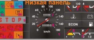
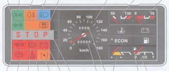
Care and safety precautions must be observed. Antifreeze is a highly toxic material. We monitor the temperature of the tubes. It is very important that all sensors on the instrument panel work. Using them, you can determine the condition of the coolant and, in the event of a breakdown, stop in a timely manner and take action.
It is advisable to always have antifreeze for such operations, and the driver must have water. You can fill it with water for a while, but in winter, it will immediately freeze in the system, so you should go to a car service center and take the car in for repairs. If the water in the system freezes, repairs will cost you dearly.
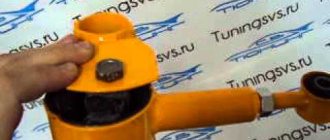
Replacing the air filter
To replace the air filter you will need a Phillips screwdriver and a filter element.
The air filter is replaced as follows:
- unscrew the four screws securing the housing cover;
- remove the filter element, remembering the location of the arrow marked on it);
- insert the filter element (the arrow marked on it must coincide with the direction of flow;
- close the lid;
- tighten the four fastening screws at the same time, without distortion.
It is recommended to replace filters every 30,000 km, but it can be done more often if the vehicle is operated in conditions of high dust concentration in the air.