Modern cars are equipped with active safety systems that help avoid loss of control of the car in various driving situations. Some models use more than ten such systems. The first was anti-lock braking system (ABS), which is still common today, and is used even on budget versions. ABS is also the basis for a number of other systems.
Why is ABS needed in a car?
ABS is needed to prevent the wheels from completely locking when braking, which eliminates the possibility of skidding and reduces the braking distance. The theory behind the anti-lock braking system is that when braking, sliding friction occurs between the locked wheel and the road surface, the force of which is lower than rolling friction (when the wheel rotates). In addition, when sliding, lateral forces prevail over longitudinal ones and it is easier for the wheel to “go” to the side than to maintain a given trajectory - a difficult-to-control skid occurs. But if the wheel turns during braking, the car will not skid and will maintain its trajectory, and the braking system will work with maximum efficiency.
What is ABS
Everyone knows this abbreviation, an abbreviation translated from English as anti-lock braking system.
In fact, in its simplest form, it is an electromechanical system that copies the actions of an experienced driver and provides effective braking on slippery roads.
If it is installed on a car, it makes life much easier for novice drivers. Although you shouldn’t place too much hope on it - ABS only helps the driver control the car, and does not control it itself.
So, the driver must know his car, its behavior in various situations and on different road surfaces, including its behavior taking into account the operation of additional systems.
What does the anti-lock brake system consist of?
ABS includes two components - electronic and executive module. The first controls the speed of rotation of the wheels on the car and, based on this, sends signals to the module, which prevents the wheels from completely locking.
Electronic component
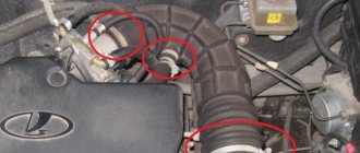
The electronic component includes a control unit and tracking devices installed on the wheel hubs and an abs sensor.
Sensors are the main element of the entire system, since the operation of the ABS depends on their readings. Previously, passive sensors were used on cars. Modern models use active sensors. Both options consist of two elements - a tracking device, installed on the stationary part, and a master device, located on the rotating part of the hub.
Operating principle of ABS sensors
In passive sensors, the tracking component creates a magnetic field. The setting element, passing through this field, leads to its changes. As a result, a pulse voltage is induced in the tracking component, which acts as a signal for the electronic unit.
In active sensors, the operating principle is different. In them, a changing magnetic field is created by master components (multipole rings). The tracking elements are supplied with voltage from a third-party source. The influencing field leads to changes in voltage parameters (in magnetoresistive sensors the resistance changes, in Hall elements the voltage itself changes). These changes are sent to the unit, which uses them to calculate the wheel speed.
Video: ABS - pros and cons of the anti-lock braking system
The electronic unit is a control element. Based on the signals received from the sensors, it determines the rotation speed of each wheel and, based on the information received, sends signals to the executive module to make adjustments to the operation of the braking system.
Executive module
You can influence the brake mechanisms, through which the wheels slow down, by changing the pressure in the brake system drive. Therefore, the executive module is embedded in the brake drive and lines coming from the main brake cylinder approach it, and pipelines extending from it to the brake mechanisms come out of it.
The executive module includes:
- intake and exhaust valves;
- hydraulic accumulator;
- return pump with electric motor;
- damper chamber.
There is one set of valves (inlet and outlet) for each brake mechanism. One damper chamber and one hydraulic accumulator are used per circuit. As for the pump, there is one per executive module. The elements are connected to each other by pipelines.
The module rings the drive line, which allows, if necessary, part of the working fluid to be pumped through the formed ring from the module output to the input.
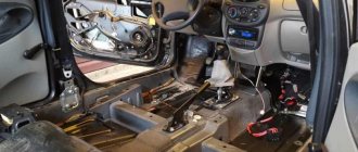
How to repair wiring
We remove the wheel, and then the locker (for the front wheel, turning out the fastening screws) or the protective shield (for the rear wheel, turning out the two fastening nuts “10”). Press the latch and disconnect the block with wires from the ABS sensor. We inspect the connector and make sure there is no corrosion or damage. In case of damage, we restore the integrity of the wires:
We treat it with a special means for cleaning electrical contacts (for example, graphite grease) and clean the contacts from oxides. We clean the wheel speed sensor and the surface around the sensor from dirt.
Attention! Keep ABS sensors away from magnets as this may cause damage.
Principle of operation
The operation of the executive module is cyclical and includes three phases:
- Increase in pressure. When braking, the brake cylinder creates fluid pressure, and it moves freely along the line to the mechanisms. Direct movement of fluid results in an open inlet valve, while the outlet valve is closed. As a result, the pressure on the mechanisms increases and the wheel slows down intensively.
- Hold. If the control unit, based on sensor readings, has detected faster deceleration of one of the wheels, then it sends a signal to close the inlet valve of this wheel (the exhaust valve is also closed). As a result, the increase in pressure on the mechanism stops, the wheel stops slowing down, since the friction force on the mechanism stops at the same level.
- Reset. In the case when the unit “notices” that the wheel on which the holding phase was applied is still slowing down faster than the others, it sends a signal to open the exhaust valve (the intake valve remains closed) and the pressure in the line is released due to the flow of part of the liquid into the one created by the module ring - the brake mechanism is released.
When the outlet valve opens, the liquid first enters the hydraulic accumulator (acts as a container for collecting excess). If a lot of liquid is discharged and the battery volume is not enough, a pump is activated, which pumps the excess into the line at the module input.
Since the operation of the pump creates a pulsation of liquid, to eliminate this negative effect, after the pump it is first supplied to the damper chamber, where the pulsation is smoothed out, and only then into the main line.
The operating speed of ABS is very high. When the car slows down, the system operates up to several hundred times, changing phases to slow down the car. ABS works constantly on the car and cannot be turned off.
When did ABS first appear?
ABS is an anti-lock braking system that prevents the wheel from locking during heavy braking, leaving the car in control.
The development of this system began back in the late 30s, and only in 1978 did motorists get the opportunity to install ABS on premium cars as an additional option. The structure of the ABS unit is a system of sensors that take into account the speed of rotation of the wheels, a brake fluid pressure sensor, the control module itself and the hydraulic unit as the final performer.
Types of ABS
| Generation | Characteristics | ||
| Weight, kg | Number of components | Memory capacity, kb | |
| ABC 2 (1978) | 6,3 | 140 | 2 |
| ABS 2E (1980) | 4,9 | 40 | 8 |
| ABS 5.3 (1995) | 2,6 | 25 | 24 |
| ABS 8 (2003) | 1,6 | 16 | 128 |
All of the above applies to the option if the car has the latest generation anti-lock brake system, or the so-called four-channel ABS.
In this case, the blocking of each wheel is monitored, and the electronics takes corrective action for each of them. This system is the most expensive and complex.
However, there are other types.
Thus, a single-channel anti-lock braking system controls braking force simultaneously for the entire vehicle. This version of ABS is much simpler and cheaper, but it works well when the grip of all wheels is equal.
A dual-channel anti-lock braking system controls braking force along one side.
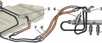
How does the ABS sensor work?
Initially, passive sensors were installed on cars, which could not detect wheel speeds of less than 5-7 km/h. Since the nineties of the last century, active sensors began to be installed in ABS. The main difference from passive sensors is that active sensors operate from a power source.
ABS sensor on the front wheel
At first, the ABS system sensors were magnetoresistive, then more accurate sensors using the Hall effect began to be installed in anti-lock brake systems.
At first these were magnetoresistive sensors. They consisted of an energized induction ring that was mounted on the wheel hub. During rotation, a magnetic field was created, which forced the direct current electrons to change their trajectory, thereby increasing the resistance. It was the information about the change in resistance that the ABS sensor transmitted to the control unit. They could detect the rotation speed from the moment the car started moving. The design of modern ABS sensors in cars changed back in the last century. And this is due to the use of the Hall effect in them. Now its work is that a semiconductor wafer is installed in the sensor itself, a permanent magnet ring is installed on the hub, next to the brake discs , and when the wheel rotates, a magnetic field is created, which causes electrons to move to one of the edges of the wafer, the microcircuits convert the signal and transmit it to ABS control unit. This sensor is more accurate, since it does not have a pulsed nature, but the microcircuits have increased the cost of the system, in addition, the microcircuit may fail due to road irregularities.
How to check ABS sensors - visual inspection
Alternatively, the ABS system can be checked using an ELM-327 scanner . An induction type sensor is an induction coil paired with a toothed metal disk located above an impulse rotor connected to the drive shaft or wheel hub. If the sensor is broken, you can find out with a tester, a soldering iron , or repair pin Next, proceed to measuring the resistance voltage in the node.
Around the pole core there is a winding connected to the magnet. This proximity allows the magnetic field to freely pass to the inductor. And since the rotor rotates and the interdental cavities change, the magnetic flux passing through the winding core changes. Such changes create alternating voltage, the level of which must be measured. The voltage frequency and amplitude depend on the number of wheel revolutions.
The pins are attached to the connectors, and the tester measures the resistance of the abs sensor. When measuring, the resistance rate is within 800-1200 ohms , but it is better to look at the passport and check with the permissible unit. When the network increases to infinity, a network break has occurred, and if the resistance shows zero, then a short circuit has occurred in the sensor circuit. To conduct a complete diagnosis of the sensors, you need to test all the wiring of the device with a tester. When everything is normal the readings will be like this:
- insulation resistance level – more than 20 kOhm ;
- leg – front right abs sensor 7-25 Ohm ;
- leg – rear right ABS sensor 6–24 Ohm .
When a breakdown is detected during inspection of the sensor, there is no point in repairing it. If a malfunction is not found, then it is not recommended to interfere with the operation of the central unit yourself. Technicians will review the fault codes previously stored in the device and take appropriate action.
Driving along a snow-covered road, the ABS indicator came on, there was 15-20 centimeters of snow on the road, I was driving along the right side, while the left side was following a well-worn track. Because I have ABS, then this is not just a contact closure. I looked into Google, the most common breakdown of this unit (if there is ABS itself) is a break in the wiring from the sensor plug. I was tormented for a month by the fact that the ABS indicator was on. But when I looked in, I didn’t notice anything suspicious; I didn’t want to take it to the service station, there was no hole. But somehow it caught fire and decided, after lying around in the snow, to find what was wrong, I got down on my knee, once again looking under the car, and there was the plug, hanging right under the right threshold, one wire had broken off from the plug, the insulation of the second had burst.
How does the ABS sensor work in simple words?
Driving a vehicle with ABS and without anti-lock wheels
When a wheel is blocked, a signal is sent from the sensor to the ABS control unit, which in turn sends a command to reduce the braking force on the wheel.
The operating principle of the ABS sensor is as follows. During sudden braking, the system collects information that the wheel is not rotating, while the car is still moving. Next, the ABS sensor transmits information to the main brake system, indicating that it is necessary to reduce the braking force on this wheel, due to which the wheel lock is removed and the car comes out of the skid.
Brake system "Lada Kalina": diagram, mechanism and system design
One of the disadvantages of the ABS of this car, like many others, is the possible failure of the electrical part of the control unit. Bad roads and shaking may destroy the soldering (or the soldering from the factory was initially of poor quality), and the ABS will fail. If liquid gets into the block, a short circuit occurs, oxidation and subsequent rotting of the components. The main thing is not to hesitate and immediately take it to a service center or manually clean the board and solder the questionable elements. ABS repairs are carried out by automotive electricians.
How to brake correctly in a car with ABS?
ABS system control unit on a car
To improve the performance of the ABS system, you need to remember and follow a few simple rules.
In theory, everything is simple in case of emergency braking - pedal to the floor, and the ABS unit will do the rest itself. But in practice this does not always happen. In order to get the most from the anti-lock brake system, significantly increase braking efficiency, reduce the likelihood of wheel locking and skidding of your car, improve maneuverability on wet asphalt, and reduce tire wear, you need to follow simple rules:
- The brake pedal must be pressed smoothly, with increasing force.
- Do not release the pedal during reverse kickback.
- Use tires according to the season.
- Do not completely rely on the system, since the ABS unit does not always work correctly.
But, like everything, the system has its drawbacks. On a road with a loose surface, be it snow or sand, ABS will not help you, but, on the contrary, will lengthen the braking distance.
How to modify the design
To protect the wiring harness from the environment, you can use a D-shaped seal. We lay the wires in it and wrap it with electrical tape. We put everything in the corrugation. We glue the cover covering the ABS sensor connector around the perimeter with the same sealant. This will prevent moisture and dirt from entering the area where the sensor and connector are located.
Attention! If the ABS fails, the brakes remain operational, but the braking efficiency is reduced, which is especially dangerous on some surfaces. See why.
1200 rub. for the photo report
We pay for photo reports on car repairs. Earnings from 10,000 rubles/month.
Write:
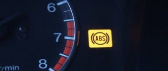
Some car enthusiasts are afraid that when the ABS light is on, it somehow affects the operation of the braking system as a whole. They urgently begin to scour the entire Internet in search of an answer to why the ABS light is on and what to do. But don’t panic so much, the brakes on your car should be in perfect order, only the anti-lock system will not work , which, in principle, is not critical, although in some emergency situations it helps a lot. To understand the system, I recommend reading about ABS.
Features of the system
ABS is installed on the braking system and makes its own adjustments to its operation. From the name itself you can understand that its task is to prevent wheel locking during braking.
The peculiarity of car wheels is that their rolling friction force is higher than sliding friction. That is, a wheel that rolls has better adhesion to the road surface than a wheel sliding along the road surface, which happens if it is completely blocked. As a result, the braking distance of the car increases.
Also, wheel sliding does not always occur in a straight direction, since lateral forces can prevail over longitudinal ones, which is why the trajectory of movement of such a wheel changes. The result of this is unpredictable and uncontrolled movement of the machine.
But if you create a force on the braking mechanism that will slow down the rotation speed as much as possible, but without blocking it (keeps it on the edge), then the braking distance will be shortened and the car will not lose control.
In cars without this system, experienced drivers use the method of repeatedly pressing the pedal (intermittent braking) to obtain maximum braking effect. To prevent the wheels from becoming blocked, the driver presses the pedal when braking, then releases it and repeats this many times.
The essence of this method is very simple - to catch the moment on the brake mechanisms when they slow down the wheels as much as possible without causing them to lock, but this is not always possible, especially if the wheels are moving on different surfaces.
Intermittent braking (press and release) does not allow the wheels to completely lock, since the driver simply periodically loosens the force on the brake mechanism. ABS uses the same principle.
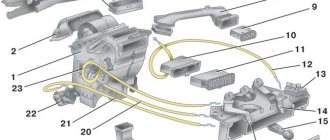
Overview of individual elements
Diagram of the Kalina brake system:
| 1, 5, 13, 16 | Brake mechanism of the Kalina front wheel, including pads, caliper, disc, cylinder |
| 13, 16 | Brake mechanism of the Kalina rear wheel - pads, drum, cylinder |
| 2, 6, 12, 17 | Hoses going to the cylinders |
| 3, 7, 11, 18 | Tubes |
| 4 | Brake Master Cylinder (Brake Master Cylinder) |
| 8 | GTZ tank |
| 9 | Vacuum brake booster (VUT) |
| 10 | Brake pedal |
| 14 | Fluid pressure regulator in the TC of the rear wheels |
| 15 | Regulator knob |
GTZ and brake pedal
The main brake cylinder has not undergone any changes compared to previous Lada models like the VAZ-2110. It is attached to the vacuum brake booster and the force from the brake pedal is transmitted through the VUT.
On top there is a tank with two sections and with measuring notches to control the liquid level. A sensor located in the reservoir lights up an indicator on the dashboard when the brake fluid level drops.
Tubes extend from the GTZ to both circuits. It is due to the main cylinder that the fault tolerance of the entire structure increases. When the vacuum booster rod enters the cylinder and pushes the first piston, the primary circuit pressure increases and the brakes are applied. Due to the pressure, the second circuit also operates synchronously, providing uniform force on both axes.
Master brake cylinder
Since the car is front-wheel drive, the circuits are located diagonally, evenly distributing the force in case of failure of one of the circuits. For rear-wheel drive vehicles, the contours are divided into axles:
- first circuit – front axle;
- the second is the back.
The brake pedal is standard. The exact same one is installed on many Lada cars, there are no differences. It is attached directly to the vacuum booster.
The brake pedal article number is 1118-3504010. Price around 300 rubles;
GTZ article number – 1118-350501082. Costs about 1500-2000 rubles.
The vacuum brake booster, like power steering, is designed to reduce the amount of force applied. The driver of a car without VUT would have to press the brake pedal hard, reducing safety and driving comfort.
Design and purpose of components
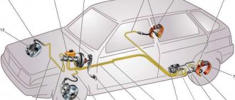
The anti-lock braking system consists of three main components:
- Wheel speed sensors
- Control unit (module)
- Actuator
Car ABS elements
As noted, this system is often used as a basis for others. At the same time, the components of a number of other systems are only an addition to the ABS.
Sensors
Speed sensors are very important components, since the operation of the ABS system is based on their readings. Based on the pulses they supply, the control module calculates the rotation speed of each wheel, and based on the calculations, the actuator is controlled.
Location of the speed sensor on the wheel hub
The ABS design uses two types of sensors. The first ones are called passive sensors. These elements are of the inductive type.
Their design includes the sensor itself, consisting of a winding, a core and a magnet, as well as a gear ring used as a driving element. The ring gear is mounted on the hub, so it rotates with the wheel.
Inductive type sensor
The essence of the functioning of the passive element is very simple - the winding generates a magnetic field through which the gear ring passes. The existing teeth, when passing through the field, influence it, which ensures the excitation of voltage in the sensor. The alternation of teeth with cavities ensures the creation of voltage pulses, which make it possible to calculate the speed of rotation of the wheel.
A negative quality of passive sensors is the lack of measurement accuracy when driving at low speeds, which can cause the ABS system to not work correctly.
Now, due to the existing drawback, passive sensors are not used in the anti-lock braking system and have been replaced by so-called active elements.
As in the first option, active sensors consist of two main components - the sensor itself and the setting element. But in active elements, sensors are built either on the magnetoresistive effect or on the Hall effect. Both options require power supply to operate (the passive elements generated it themselves).
As for the driving element, the design uses a ring with magnetized sectors (multipole).
Design and principle of operation of an active speed sensor
The essence of the work of active elements is different. In the magnetoresistive version, a constantly changing field (from the master ring) leads to changes in the resistance readings in the sensor. In a Hall element, this field changes the voltage itself. In both cases, an impulse is created, from which the rotation speed can be calculated.
Active type elements have become widespread due to their high measurement accuracy at any speed.
Control block
The ABS system control module, like other ECUs involved in car systems, is needed to receive and process impulses transmitted from wheel sensors. It contains tabular data on the basis of which it controls the actuator. That is, after receiving a signal from each sensor, it compares it with the information entered in the table, and based on the results obtained, it will determine what it should do.
In a car with a number of systems based on ABS, the control unit has additional modules responsible for the operation of its systems.
Actuating mechanism
The actuator (also called a hydraulic unit or ABS module) is the most complex in design and consists of a number of elements:
- solenoid valves (inlet, outlet);
- pressure accumulators;
- return pump;
- shock-absorbing chamber.
ABS unit design
In the classic scheme, only one line goes to the brake operating mechanism, through which fluid is supplied from the master cylinder. In ABS, the return line is embedded into it, but it only passes inside the module.
What to do if the ABS light is on?
It is worth noting that the system works normally if the ABS icon lights up when the ignition is turned on and goes out after a couple of seconds. The first thing to do if the ABS light is constantly on is to check the fuse for this system, and also inspect the wheel sensors.
Quite often, the sensor connector on the hub either oxidizes or the wires fray. And if the ABS icon is on after replacing the pads or hub, then the first logical thought is that you forgot to connect the sensor connector . The presence of dirt on the sensor also causes the indicator to light up.
Quite often, car owners may be frightened by the appearance of an orange ABS icon after a good slip. In this case, you shouldn’t bother at all: brake sharply a couple of times and everything will go away on its own - the control unit’s normal reaction to such a situation. When the ABS light does not light up constantly , but periodically, then you need to inspect all the contacts, and most likely, the cause of the warning light can be quickly found and eliminated.
Generations and species
The modern system installed on a car is four-channel. It includes two valves for each wheel, as well as one pressure accumulator and shock-absorbing chamber per circuit (of which there are two).
In general, this system already has 5 generations. The first of them appeared in 1978, the second replaced it in 1980 and was installed until 1995, after which the 2nd generation replaced the 3rd. The modern 4th generation of the system appeared in 2003, and now the 5th generation is in use, which continues to be used to this day.
In terms of design features, the four-channel system is the latest and most technologically advanced. But it was preceded by:
- single-channel system (it used only two valves, which regulated the pressure in all lines simultaneously. It is noteworthy that in the single-channel type the system usually made adjustments only in the drive axle mechanisms, that is, the ABS worked only with two wheels);
- two-channel (in this type of ABS, the brake mechanisms are divided along the sides, each of which has its own set of valves. That is, one channel combines the mechanisms of the front and rear wheels of one side);
- Three-channel (it provided one set of valves for the wheels of the rear axle, and the front ones were each equipped with its own channel).
Nowadays, these three types of ABS systems are found only on older cars.
Operating modes
The anti-lock braking system can operate in three modes:
- Pumping. In this mode, the brakes operate as usual. After pressing the pedal, the fluid goes to the mechanisms, the wheel slows down its rotation. In this mode, the inlet valve is open and the outlet valve is closed, that is, the liquid moves only along the supply line;
- Hold. If the unit calculates from the signals that one of the wheels is reducing rotation faster than the others, it will close the intake valve. As a result, the force of the mechanism will stop increasing, so the deceleration of the wheel stops at a certain level. On other mechanisms, the force will continue to increase;
- Pressure release. If, even after switching to the holding mode, the wheel still continues to slow down, the control unit activates the exhaust valve (closes the inlet valve) and part of the fluid goes into the pressure accumulator, thereby reducing the pressure in the mechanism (the wheel is released and begins to increase speed). As stated above, one battery is intended for two brake mechanisms (part of the circuit). There are situations when the pressure is released from both of these mechanisms at once, so the volume of the battery may simply not be enough. And then the pump starts working, pumping the excess into the main line.
ABS system diagram
During braking, the system changes its operating mode many times, which ensures effective braking. At the same time, the driver does not need to “play” with the pedal to prevent wheel locking; the system does everything itself.
Common breakdowns
A slight cracking sound when pressing on the brake pedal is quite normal. This sound occurs due to the functioning of modulators. If the ABS is faulty, its indicator lights up and does not go out even when the engine is running. There are several most common malfunctions of the anti-lock braking system:
- Deactivation based on self-diagnosis results. This may be caused by a malfunction of the control unit or damage to the ABS touch sensor wiring.
- After activation, ABS self-diagnoses, but then turns off. This problem can be caused by broken wires, broken contacts or their oxidation, where the supply of power and signals is disrupted.
- An error appears, but the ABC sensor works. This is a consequence of a break in the touch sensor. It can also be caused by differences in tire pressure or even different tread patterns.
- Complete loss of system functionality. There can be a lot of reasons for this, ranging from sensor breakdowns to wear of the wheel bearings.
To identify a malfunction, you need to check the pressure and play in the tires, the performance of the comb and rotor. If the elements have chips, then it is better to completely replace them. If the problem remains unresolved, then the reason most likely lies in the electronic component. In this case, you need to get a diagnostic code.
Advantages and disadvantages
Other advantages of this system also include:
- maintaining the trajectory of movement during braking when entering a turn;
- maneuvering is allowed when braking;
- convenience for novice drivers.
But ABS is not perfect. Under certain conditions, this system may not function correctly and may make errors. And this affects the effectiveness of braking and can somewhat disorient the driver.
These conditions are:
- road with problematic surface;
- sand;
- ice;
- surface with bumps, “comb”.
In general, ABS works great only on a flat road with good wheel grip. In other cases, the ABS system may make errors.
For example, on a problematic highway with frequently alternating surfaces (the asphalt alternates with crushed stone or other bulk material), the system will not be able to select the optimal force on the mechanisms, which is why the braking distance increases.
When flying off the road, ABS is also not a “helper”. Here, blocking is the best way to stop the car as quickly as possible.
The peculiarities of the anti-lock braking system also include some delay in activation when driving at high speeds (over 130 km/h). It’s just that under such conditions the control unit needs some time to make calculations and engage the valve body.
At low speeds (10-15 km/h), the system turns off completely. If this is a stop on a flat surface, then turning off the ABS has no effect, but when braking on a descent, deactivating the system can have a negative impact.
Note that disabling ABS is a relative concept, since the system operates constantly and cannot be turned off. Here, deactivation should be understood as a transition to “standby mode”. That is, it is activated again and will begin to perform its function the next time you press the brake pedal. The only time it won’t turn on is when braking when driving at low speeds.
Diagnosis of ABS faults
The most expensive part to replace is the control unit, but as mentioned above, it is protected by a relay, which reduces the risk of its breakdown. The only thing that can disable it is a temperature difference, which we also described above. Therefore, the central part of the system can be safely excluded or moved to the last check point.
Do-it-yourself ABS diagnostics starts with the front wheels:
- We remove the sensor.
- We clean it from dirt and accumulated deposits with kerosene or white spirit.
- We inspect the teeth on the wheel hub. It is from them that the sensor reads high-speed revolutions; when the teeth are clogged with dirt, then the data is read incorrectly, which leads to the ABS freezing.
- We remove blockages from them, and we do the same with the reverse gear sensor.
- Afterwards, you need to check the electrical resistance, which is specified in the vehicle’s factory manual. When you cannot find out the exact resistance, go to the store and ask the seller about the resistance for your vehicle model.
- When everything is in order with the sensors, switch the multimeter to voltmeter mode, which measures alternating voltage.
- Raise the car with a jack and spin the wheel, and while rotating it, measure the voltage in the sensor winding. You can also find out the normal unit of voltage from your car's manual.
- Let's move on to the bearings. Wheel hub wear is the most common cause of system failure. You still need to clean them from dirt with kerosene and check them by shaking them. If they are faulty, it will be revealed immediately. It is necessary to replace worn elements and check the operation of the sensor with a multimeter.
Improvements and improvements
Engineers have brought the ABS design to a high level and there is practically nothing to improve. Only some components are subject to modifications. Thus, wheel sensors now not only measure rotation speed, they additionally integrate G-sensors and accelerometers.
Improvements also include increasing the functionality of the electronic unit (that is, the use of ABS as a basis for other systems). For example, the ABS control unit is used in the traction control system and brake force distribution.