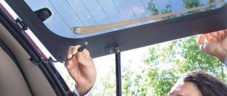
Heated rear window is a useful and very convenient option that allows you to avoid fogging and freezing of the rear window and at the same time provides excellent visibility at any time of the year.
Heated rear window saves not only in winter, but also in autumn, when humidity rises and all the windows in the cabin begin to fog up. In just a few minutes, heating the rear window melts ice and light snow, and also dries the condensation that accumulates on the glass in wet weather.
All this is good, but what to do when nothing happens when you press the button, in other words, what to do if the rear window heating does not work? This is exactly what we will try to figure out today. You will learn how the heating works, why it fails, and also how to find a fault and repair the heated rear window of a VAZ.
What affects traffic safety?
Almost all heating systems are electrical appliances and they are not particularly reliable. But if the heated seats or steering wheel does not work, then such malfunctions only affect comfort, and you can completely do without them.
But the lack of heated rear window and side mirrors can become a serious problem, since in this case there is already a negative impact on traffic safety.
With the rear window and side mirrors frozen, the driver is completely deprived of visibility of what is happening behind the car, and in such conditions it is not far from an accident.
Also, any reversing without a normal view from behind is an unpleasant and, in winter, a dangerous procedure, since to assess the situation the driver needs to lean out of the window and control the movement in this not very comfortable position.
Features of the placement of fuses in the Lada Granta Liftback
The Grant Liftback fuses are located near the driver’s left hand.
To gain access, simply remove the decorative plug by pulling it down.
To make it convenient to work, the plug can be removed completely, for which you pull it out of the grooves, on one of which the trunk opening button is fixed (this can also be removed; it applies to the “luxury” and “norm” modifications).
Purpose and design
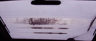
The purpose of the rear window heater can be judged by the very name of the system - by heating it fights condensation that settles on the surface, the cause of which is the difference in temperature in the cabin and outside.
In the autumn-spring period, this condensation causes “fogging” (a water film is formed, which greatly limits visibility), and in winter it turns into ice and frost, through which it is generally impossible to see what is happening behind.
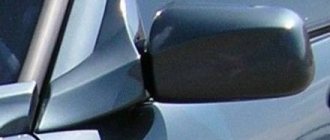
As for the side mirrors, they are located outside and should not “fog up” or freeze, since there is no temperature difference as such. But there are other reasons why a water film and frost form on the surface of the mirror, reducing visibility.
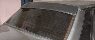
The design of any heater is very simple, and on all cars they are built according to the same principle. If we consider only the rear window, its heating system includes:
- Conductive threads and busbars applied to a transparent surface (from the inside);
- Heater power cables (powered from the on-board network);
- Protective elements (relay, fuse);
- Controls (power key with signal diode installed on the front panel).
The main working element in this chain is the threads running along the surface. They have a fairly high resistance, which ensures their heating when electric current passes through them.
The threads are connected to tires laid along the edges of the glass, together with them they form a grid corresponding to the size of the heated area. One of the buses is connected to the power circuit, and the second is connected to ground.
Power supply diagram and operating principle
The heated rear window is powered not directly from the energy source, but through the ignition switch, and there is a logical explanation for this.
Like any heating element, it consumes a large amount of electricity during operation, so to prevent the battery from discharging (if the driver forgot to turn off the heating), it was powered through the ignition switch.
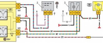
In general, the power supply circuit is as follows: the electric current after the lock passes through the fuse and is supplied simultaneously to the output of the heating switch and one power contact of the relay (the second contact is connected by wiring to the “positive” bus of the grille).
Using the Hyundai Accent as an example, it looks like this.
When turned on, the key closes the circuit and the voltage from it is supplied to the relay winding, as a result of which the relay closes its power contacts and the current is supplied to the “positive” bus and moves along the conductive threads (which causes them to heat up) to the “minus” bus.
The circuit diagram is shown below.
Doesn't work, what's the reason?
Actually, there are only two main reasons, and both of them lie in the power system:
- Fuse. YES it can really burn out. This happens for various reasons, maybe it’s just a minor short circuit and that’s all. Thus, your heating will not work completely. You need to find the fuse and check it . This is the first and mandatory step.
- If it is intact, then we need to check the voltage on the wires that go to the main “buses” (wide side strips). As a rule, they have ordinary metal contacts. We just take a multimeter and measure it, if there is voltage and it’s about 12 Volts, that means the power is suitable here, everything is fine.
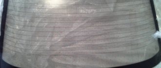
- The thin lines themselves. To be honest, they can’t all burn out at once. As a rule, from one to three, or at most four, “threads” burn out. Therefore, if part of your window comes off (from fogging or ice), but part does not. It is the non-working threads that need to be looked at.
- Examine this thin strip and you will see the break point. This will be the burnt part, there may be a little black around it (although the thread is originally brown). Also, the thread will seem to open, this place needs to be connected in order to restore functionality.
On my own behalf, I would like to add that the fuse rarely lights up, mostly it is a break in the “threads” of the glass; they need to be restored.
Malfunctions
Despite the design simplicity of the rear window heating circuit, it breaks quite often. The most common system malfunction is a blown fuse.
But there are a number of other breakdowns that can occur with the device:
- Damage to conductive threads;
- Oxidation of contacts;
- Broken power supply;
- Relay burnout.
Some of these faults lead to a complete failure of the system, others lead to a decrease in its efficiency or uneven heating of the surface (unthawed areas remain on it).
Circuit elements
A blown fuse is a common failure because the system consumes a large amount of energy during operation. The operation of glass heating under heavy load leads to the fact that the protective element fails.
Also, the relay through which the threads are powered often fails.
Conductive threads
The second common problem is damage to the threads. The thickness of the conductive path is insignificant and it is very easy to break it. Most often, the threads are damaged by the drivers themselves.
Ice forms on the interior side and many, trying to get rid of it quickly, without waiting for the heater to do it, remove it manually - using scrapers. But even the softest scraper can easily damage conductive tracks.
In this case, the system as a whole remains operational, but the broken thread will not heat up, and unheated areas will appear on the glass, reducing visibility.
One broken thread will not particularly affect the view, but several damaged paths can seriously complicate the driver's ability to assess what is happening behind the car.
The car owner has the opportunity to restore damaged threads, but this procedure is complicated by the fact that it is not always possible to visually detect the location of the break, and this is necessary to carry out repair work.
But electrical measuring instruments - voltmeters, ohmmeters or multimeters - help with this.
For example, if you have a voltmeter, the diagnostic technology is as follows:
- We connect the “negative” probe of the device to “ground”, and wrap the “positive” probe with foil (so that during the test the sharp end of the probe does not cause additional damage to the threads);
- We start the engine and turn on the window heater;
- We run a “positive” probe along a thread that does not heat up and look at the readings of the device.
The standard voltage in threads is 5 V, this is the value that a voltmeter should show when the “positive” probe touches the track. At the location of the break, a power surge will certainly occur, after which all that remains is to mark the area with the damage.
Approximately the same technology is used to check threads using an ohmmeter, with the only difference being that a break is determined by a jump in resistance.
Other problems
Other malfunctions of the rear window heating - broken wiring, oxidation of wires and broken relays - are determined and eliminated in the same ways as other electrical appliances - by testing the wires, replacing parts with known-good elements, cleaning contacts, etc.
How to find a breakdown
To find out exactly what the reasons for the failure are, you only need a standard voltmeter, which every self-respecting car enthusiast should have.
By simple manipulations with this measuring device, the problem will be identified very quickly. You should start checking the heating element filaments with the following steps:
- the metal tips of the probes are wrapped in tin foil (this will avoid damage to the tracks);
- turn on the ignition;
- check whether the heating button is pressed;
- one probe is applied to the plus of the heating element mounted on the rear window;
- the second is installed approximately in the center of the thread.
If the device shows 6 volts, this means that there is no damage in this area. If the tester produces 12 volts, the gap is located somewhere in the segment between the probes.
If there are 10 volts, we can confidently say that the gap is located between the minus and the center of the track. In this situation, connecting one probe to the negative output will allow you to more accurately determine where the damage is located. At the same time, the second one must be carefully guided along the thread from the plus to the opposite end. Finding the exact location of the break is indicated by an increase in voltage from zero to 5 volts.
If you don’t have a voltmeter at hand, then the break will also be easy to find visually. To do this, you will need to wait until the windows in the car fog up, and only then turn on the heating. Where the track remains operational, the moisture will begin to evaporate noticeably. Condensation will remain in de-energized areas. It is these sections of the heating element that will need to be examined in detail. To do this you will need a magnifying glass.
If the heating is completely out of order, it can be replaced with a removable model, which is attached to the glass using special suction cups. It is connected to the car's electrical network, like many other devices, through the cigarette lighter.
There are also modifications on sale in which an additional fan is installed. But this option is not very practical because it requires too much electricity.
Methods for recovering conductive strips
Of all the malfunctions, the most unpleasant is the breakage of current-carrying threads. In this case, the system seems to remain working, but it does not function fully.
The difficulty is caused by the fact that the strips attached to the rear glass cannot be replaced, and it is not possible to install new ones, but it is quite possible to restore them. Repairing conductive threads is a simple operation and can be done by any car enthusiast.
A number of methods are used to restore stripes.
Conductive pastes, varnishes, paints
In auto accessory stores you can purchase repair kits for restoring conductive glass heating strips, the main components of which are the specified varnishes and pastes.
The essence of the repair with their help is very simple: tape is glued to the sides of the damaged strip (so that only the thread remains uncovered), the break area is cleaned and degreased.
After this, all that remains is to apply the paste or varnish, allow time to dry (usually 24 hours), remove the tape and check the functionality of the heater.
Metal powder, varnish, glue
The use of steel metal powder and a binder - varnish or glue. This method is good because all the components are at hand and you don’t need to buy anything.
The repair technology is as follows: we attach a magnet to the outside of the glass at the break site, and cover the break site with tape on the sides.
Using a file from any metal part, rub the powder, which we apply to the tear site (the magnet will hold it), then coat it with varnish or glue, and after drying, remove the tape.
The essence of the method is that metal powder, held by a magnet, will connect the strips of the heating system to each other, eliminating the gap, and simply fix the resulting bridge with varnish or glue.
Application of non-ferrous metal chips
Application of shavings from non-ferrous metals (copper, brass) and binders. This method is characterized by high repair speed and ease of implementation.
The technology is as follows: we cover the break area with tape. Mix the components - shavings and glue (varnish) in even proportions. Heat must be turned on before application.
And then we simply apply the mixture with a brush, while the current passing through the strip will ensure that the applied layer dries quickly.
All of these methods make it possible to restore the rear window heating equally well.
Technological process of repair step by step
First, we determine where the chain breaks on the threads. Often these are easy to identify; they are visible to the naked eye. Usually this is mechanical damage in the form of scratches, abrasions and large torn parts.
Then we study the instructions for using the repair kit: methods for applying the conductive agent and the time until it completely dries. The next step is to prepare the surface of the damaged area for restoration. To do this, just wipe it with a rag soaked in an alcohol solution to remove dirt and degrease it.
After this, you should stick strips of adhesive tape on both sides of the thread in the area of \u200b\u200bthe break.
Repair kits and thread restoration products
When carrying out repair work, it is recommended to use repair kits designed for this purpose, especially since they are not particularly expensive, and they include everything necessary.
For example, a popular kit for repairing conductive threads of the glass heating system PERMATEX PER-09117 consists of:
- Degreasing wipe;
- Sandpaper for stripping threads;
- Adhesive compound;
- Activator;
- Conductive glue;
- Self-adhesive template.
But in addition to repair kits, you can also purchase simply conductive adhesives or pastes.
In general, the choice of means for repairing rear window heating is very extensive and allows you to find a suitable option for any car owner.
Below is just a small list of adhesives and kits for such work:
- Set PERMATEX PER-21351;
- Glue for repairing threads “Kontaktol”;
- Conductive glue “Astrokhim”;
- Matrix glue;
- Conductive paint "Pro Glass";
- Glue "AVS Crystal".
And there are many such means. But at the same time, it is important to understand that very cheap glues and varnishes are not always of high quality and allow you to properly eliminate breaks.
Features of the mirror heater device
Heated side mirrors are another system that affects driving safety, although not to such a significant extent as the counterpart for the rear window. Therefore, it is still considered an optional equipment, which is not found on all cars.
Note that this is not a separate system, but an additional one. In fact, it consists only of conductive strips applied to a special substrate, which is fixed to the inside of the mirror.
The subsystem is connected to the power supply circuit of the glass heating and they are switched on together.
The presence of a mirror heater makes it somewhat easier to identify the cause of the malfunction. Everything is very simple - if both devices do not work at the same time, the breakdown should be looked for in the fuses, relays and control key.
But when only one of the heaters does not work, the wiring to them and its connection points and conductive strips are checked.
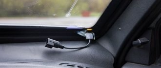
We gain access to the fuse box in the cabin
In the Lada Granta, the fuse box, or as it is also popularly called, the mounting block, is located to the left of the driver. To gain access to it, you need to lower the protective decorative plug down.
Removing the decorative plug
Location of the latches of the decorative plug of the mounting block
Removed from one mount
For ease of use, I recommend completely removing the decorative plug and putting it aside. To do this, you need to remove the chip from the trunk opening button. The chip can be easily removed; there are no latches that hold the chip in place.
Remove the chip from the trunk button
Also, the chip is made for fools; you won’t be able to put it on incorrectly, so you don’t need to remember its seating position.
Seat heaters
Heated seats are another system that is becoming more common on cars. Although it is completely separate, it is built on the same principle as the heated rear window.
Therefore, their reasons are similar:
- Damage to conductive strips (laid in the seat);
- Broken wiring;
- Fuse blown;
- Control key malfunction;
- Relay burnout.
And since the general principle of constructing heaters is the same, the repair methods are similar. It is only important to know where the circuit components are located and how the wiring is routed.
Fuses and relays, where to look for them?
Since most often the cause of non-working heating is a fuse and relay, before performing diagnostics and repairs, you should first find out where these elements are located, and each car has different locations.
VAZ-2107
On the VAZ-2107, the relay and fuse responsible for the rear window heating are located in one mounting block, installed in the engine compartment on the right near the engine shield.
In the electrical diagram, the relay is marked “R1”, but it can be visually identified by its location - it is on the far left.
As for the fuse, its marking is “F5”, and in the block it is located third from the left in the second row of fuses.
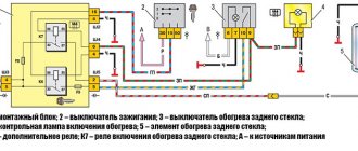
VAZ-2114
On the VAZ-2114, these elements are also installed in a mounting block installed near the engine shield, but they are located slightly differently.
The relay responsible for the operation of the glass heating on this car in the diagram is designated “K7”, and it is located in the second row of relays in the center.
The fuse is marked with the index “F4” and it is installed in the left row of fuses, fourth from the top.
Lada Priora"
On the Lada Priora, the relay and fuse should also be found in the mounting block, but it is located in the cabin, under the dashboard on the left side (closed with a decorative cover).
In the diagram of this car, the rear window heating relay is designated as “K1” and it is installed in the top row, second from the left.
As for the fuse, its marking is “F2” and you need to look for it in the top row of fuses, where it is installed second from the left.
Lada "Kalina", "Granta"
In the Lada Kalina, the required components are placed in a mounting block, which, like the Priora, is installed on the left side of the dashboard and closed with a lid.
The required relay in this car is designated by the index “K10” and it is installed in the second row of relays in the middle (it is located a little separately from the others).
The fuse in the diagram is designated as “F8” and it is installed in the top row, eighth from the left (approximately in the middle).
In the Lada "Grant", the placement and designation of the components of the heating system circuit does not differ from the "Kalina".
Reno Logan
But in Reno Logan, the designers did something quite interesting, but inconvenient for car owners. Two fuses are responsible for heating the rear window (“F01” is the power circuit, which also powers the windshield wipers, and “F32” is the relay winding circuit) and they are both installed in the mounting block.
To get to the unit, open the driver's door and remove the cover installed at the end of the front panel.
Fuse “F01” is the top one on the left, and “F32” is at the bottom of the block in the middle row (there is only one there).
As for the relay, its designers moved it outside the mounting blocks and installed it separately. You should look for it under the front panel on the left side (driver's side).
Chevrolet Lacetti
The Chevrolet Lacetti also uses a split circuit with two fuses. The first of them, marked “F6,” is located in the interior mounting block (sixth in the left row). The block itself is located at the end of the front panel on the left.
This protective element is responsible for powering the relay windings of a number of equipment - heated glass, air conditioning compressor, headlights, power windows.
Scheme for switching on heated glass and mirrors.
Another fuse – “Ef7”, responsible for powering the circuit, is located in the mounting block installed in the engine compartment (behind the battery). The same block also contains a relay, designated “K10” in the diagram (the middle one in the lowest row of relays).
Ford Focus
In a Ford Focus, the power supply circuit for heating the vehicle elements includes two relays and one fuse. But one of the relays only partially relates to the heated glass - the so-called ignition relay, from which a number of control units and relay windings are also powered, including the one responsible for powering the heated rear window.
It is located in a mounting block installed in the engine compartment and is designated by the index “K8”.
As for the fuse and the relay itself, they are installed in the interior mounting block located under the storage compartment. The fuse in the circuit is marked with the index “F105”, and the relay – “K19”.
Daewoo Matiz
On Daewoo Matiz, the elements of the rear window heating power circuit are located in the mounting block installed in the engine compartment, on the right near the engine panel.
The fuse is designated “Ef7”, and you need to look for it in a horizontal row (standing on the side of the car near the fender), it is the seventh in a row.
The relay marking is “K3”, and it is on the far right in the top row of relays.
Since these circuit elements are considered irreparable and if they burn out they need to be replaced.
For replacement, you should select parts that have the same operating parameters as those that have failed. And knowing their location will greatly simplify the work. Also read how to diagnose a car using a laptop.
Part of the wiring, connection of Euro-3 class ECUs
The car is available in two versions. However, the Euro 3 version is in great demand. Pinout of the control unit Kalina model BOSCH M7.9.7, M 73 with 81 contacts:
- 1 – for the 16 valve version – ignition coil 2 combustion chambers, in the 8 valve version. not used;
- 2 – for 8 valves is responsible for 2-3 clamping coils. In 16th grade. only for 3 boilers;
- 3 – grounding to the body from a short circuit;
- 4 – not applicable for 8 valves (empty). On a more powerful version, it is responsible for cylinder 4;
- 5 – for 16 kl, supplies power to 1 kat. Clamp For anlaog, he is responsible for blocks 1 and 4;
- 6-7 – Injector driver No. 2, 3;
- 8 – electronic signal for indicating engine speed;
- 9 – not used;
- 10 – gasoline consumption indicator;
- 11 – empty;
- 12-13 – from the battery to the ignition;
- 14 – main relay – current supply;
- 15 – DPKV input response;
- 16 – reception from the TPS sensor;
- 17 – similar element – grounding on the car body;
- 18 – response from DK 1;
- 19 – knock sensor input;
- 20 – land DD No. 2;
- 21-26 – not used;
- 27 – drive of the first nozzle;
- 28 – heater DK2;
- 29 – power output of the control unit for coolant fan No. 2;
- 30 – free;
- 31 – lamp performance – check the engine;
- 32 – TPS controller;
- 33 – power supply to the mass air flow sensor;
- 34 – receiving an impulse from the DPKV;
- 35, 36 – ground of the corresponding sensors;
- 37 – impulse transmission channel from the mass air flow sensor;
- 38 – empty;
- 39 – power output of antifreeze temperature sensor;
- 40 – DTVV – signal reception;
- 41-43 – not used;
- 42 – receiving an impulse from the DNRD;
- 44 – per main module;
- 45 – for phase distribution sensors;
- 46 – adsorber valve, control part;
- 47 – voltage for injector No. 4;
- 48 – heater circuit DK1;
- 49, 52, 54, 56, 58, 60, 62 – empty;
- 50 – extra Starter relay;
- 51, 53 – taps to the ground;
- 55 – pulse receiving line from DC2;
- 57 – calibration of short circuit to ground;
- 59 – speed sensor sensor;
- 61 – on the body;
- 63 – from the main control relay;
- 64-67 – XX calibrators;
- 68 – control of cooling system fan No. 1;
- 69-70 – power lines for the fuel pump and air conditioning relays, respectively;
- 71 – K-Line;
- 72-74 – not used;
- 75 – request on. Air conditioning systems inside the cabin;
- 76 – impulse to activate the power steering unit;
- 77-78 – empty;
- 79 – input from DF;
- 80 – body weight;
- 81 – empty.