The Russian auto industry, unfortunately, only recently began to really listen to consumer feedback and make adjustments to the design of its cars. For several years, the question of an integrated seat heating system has been raised, which is very relevant in cold regions. This request was taken into account, but installation of this system at the factory is carried out only on new models, and is planned for those that are under development.
Thus, consumers actually received nothing, since the Russian auto industry refuses to produce this system separately for specific car models.
Power supply or how to connect the heated front seats on the Lada Granta correctly
The cost of installation work at an unofficial service station is at least 2,500 rubles. For this money, already purchased heating elements will be installed in the car seat and the circuit will be connected according to the manual. All that remains is to make an anti-freeze product according to a home recipe and hit the road. This is for the quick ones. Painful owners will probably not like the electrical part of the integration.
Disadvantages of the standard kit
The instructions indicate how to install heated seats on the Grant and connect it to the on-board network. According to what is written, the electrics connect and function like this:
- The permanent plus is taken from the hazard warning button.
- The ground is connected to the bracket for fastening the standard wires of the negative pole.
- The standard fuse is replaced with a more powerful one.
- The heating is turned on/off using the buttons directly.
Only one function is correctly implemented - turning off the heating when the ignition is turned off. Otherwise, the connection scheme is not entirely successful:
- The positive wire that goes to the emergency light is thin and will probably work at the limit.
- The contact group of buttons operates in a dangerous mode, since it is not intended for power loads.
For your information. The kit offers simplified buttons for installation - they do not have a power indicator in the form of a yellow lamp (as on the rear window heating control).
Competent connection diagram
An unfortunate result of the standard connection algorithm is a melted fuse. Such a reaction indicates that the circuit is operating at its limit. An alternative scheme for connecting heated seats will help to avoid this. It involves the use of two four-pin relays and powering them from switch K4, which supplies the output “+” after turning on the ignition.
Additional items
It is advisable to carry out installation work after purchasing an additional mounting block of reduced size. You will also need regular contacts for connecting two relays and two Lyra contact elements linking a 10A fuse. We also add additional wires with a cross-section of 4 and 1.5 mm2 to the shopping list.
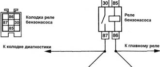
Search "+"
So, in order to connect the heated front seats on the Grant, you need to find out the number of the output plus of relay K4, which appears after turning on the ignition. This can be either the 87th or the 30th contact.
Usually this is contact element No. 30, but it doesn’t hurt to make sure once again. We remove the relay and diagnose. The test is carried out by connecting a 12V lamp to the 30th contact of the mounting block and ground. After activating the ignition, the lamp should light up.
Connecting elements
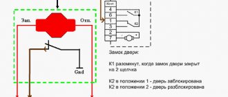
It is convenient to disassemble the connection map of the key components of the circuit in the figure. The sequence of actions when assembling the chain is as follows:
- Pull out the “+” terminal, found during the K4 relay test, and connect two wires to it: one (4 mm2) - to the fuse and then to the 87th contact, the second - the control plus from the heating button (pin No. 1). Make a jumper and integrate it back.
- On the “+” route to the seat heating relay, install a 10A fuse by integrating the “Lira” contacts.
- At the second end of the received “+”, make branches for the second switch and control button, connect them to the 87th and 1st contacts.
- Make two ground wires with jumpers that will be attached to the 85th, A and C terminals.
- Route the control wiring and the backlight wire from the buttons to the mounting block. Connect 2nd contacts to 86th; B – with fuse fastening element F9 or F10.
- Connect your “+” heating elements to the 30th contacts of each relay.
Connection
Rear seat heating connection diagram:
It is better to take contact “B” from a protected high-current circuit with a fuse. Contacts “A” and “C” can be found in the ERA-GLONASS lighting lamp, in the ISO radio or cigarette lighter connector. Before starting the connection, do not forget to disconnect the negative terminal of the battery.
Installation and connection of heated rear seats on a Lada Vesta on video in several episodes:
Let us remind you that we previously told you how to connect heated windows/mirrors to an additional alarm channel on Lada Vesta and XRAY, as well as how to turn on the heated windshield through a separate button.
Found an error? Select it and press Ctrl+Enter..
Today I finally decided to equip my car with heated seats, because summer is ending and winter is coming))), we need to prepare the sled in the summer, as popular wisdom says.. So, what do we need for this:
1. Heating pad plugged into the cigarette lighter 2 pcs. 2. Relay 90.3747 (4 pin) 2 pcs. 3. Block for relay 2 pcs. 4. Heating button VAZ 2114 2 pcs. 5. Block for buttons 2 pcs. 6. Connector to the heater (you can use the cigarette lighter socket) 7. Terminals, wires, insulation
Tools: knife, wire cutters, pliers, tester (multimeter)
For ease of operation, you can remove the front seats, but I didn’t. did this. Remove the left and right protective shields:
We unscrew the plastic rim around the handbrake and remove the sensor... without this you cannot unscrew the screw that holds the floor tunnel lining:
Remove the cover of the diagnostic connector and unscrew the connectors themselves, disconnect the cigarette lighter connector:
Raise the gearshift lever housing and remove the tunnel lining:
So, I connected all the wiring according to the diagram downloaded from the Internet. I'm not very good at electrics, so I connected it as in the diagram through the heated rear window button, although they said on the forum that you can connect to the ignition relay. but I didn’t change the scheme and did everything according to it:
This is how I sat, twisted the wires and crimped the terminals:
According to the diagram, it was necessary to get to the heated rear window button, and for this you need to disassemble the center console. Well. forward. Connected to +12V to the block. in the picture on the top right:
Here is the console itself resting on the seat:
I twisted the pins together so that everything was neat:
Then I put everything back together. Now let's see what I got... instead of plugs, there are the treasured seat heating buttons:
When the dimensions are turned on, they are also highlighted:
When you press the button, the heating indicator lights up as expected:
Since we plan to use a heating pad that plugs into the cigarette lighter under the seat, I brought out the connection chip... I haven’t bought the heating pads themselves yet, so there’s only a chip under the seat for now:
Seat heating does not work: reasons
It is not difficult to guess that the seats are heated by a special heater when power is supplied to it.
On the Niva Chevrolet there are two elements, on each of two seats, connected by a separate line, but working synchronously when turned on.
And when the button is turned on, the current passing through the relay turns on the heaters. For the best visualization of the device operation, a special indicator is provided on the button. If it does not light up, this will indicate an open circuit and inoperability of the circuit for a short circuit.
This is what the switch looks like when installed.
Checking circuit elements
If heating does not work, you need to check the following:
- Fuse with a rating of 15-20 Amperes , or a relay.
- Broken wiring or heating elements.
- Heating button . Such a malfunction is extremely rare.
The best place to start is by checking the relays and fuses. They are located in the mounting block, or rather in its lower part. They must be checked by visual inspection, or by replacement with a known-good spare part.
Connection diagram and mounting block
The required fuse is located under F15, and the relay is located under the designation “K”.
Next, you should measure the resistance, voltage and current along the wires; if it is present, then you can move on to the heating elements.
Main types of electric heating systems
As already mentioned, such systems differ in configuration, as well as in the time that may be required to install them.
. Some types of kits can be installed in a matter of seconds, while others can take about six hours.
All designs are divided into subgroups
depending on the following criteria:
According to the type of heating element used
:
Depending on the area to be heated
:
- Electrically heated seats only;
- heated seat and back area.
Depending on location
:
- easy installation on the surface of the covers;
- more complex installation under the cover.
Depending on operating modes
:
- a simple device with on and off buttons;
- begins to work upon contact with a person;
- a device that maintains temperature conditions at an automatic level, etc.
There are also two types of system designs
:
Standard heating
It is equipped with a reliable and safe design, which is quite suitable for long-term service. In this case, special threads are used that perform the heating function. Certain thermostats are built into the system. The buttons of such a device have self-locking properties. Standard equipment is designed to heat the seat and back area.
There is a wide variety of different universal heating systems
. One of the most common today is the Emelya set, which is of high quality. The elements of the kit are an order of magnitude larger in size than in standard equipment, but they also heat up faster. This will be one of the profitable options if the heating system is not installed by the manufacturer.
Schematic diagram of the VAZ 2114 stove: a separate line responsible for powering the windshield wiper
A small cable harness responsible for powering and controlling the cabin air supply box. There is also a power supply for the windshield wiper:
- 1 – part of the installation site exit;
- 2 – sensor for monitoring lubricant pressure in the crankcase compartment of the power plant;
- 3 – power lines of the aft windshield washer motor;
- 4 – voltage to windshield washer drives;
- 5 – diagram of the electric motor for windshield wipers;
- Ш11 – terminal for connection to the installation site;
- A – grounding terminals of the wiring section.
Recommendations
When installing most heated seat systems, it is absolutely not necessary to remove the seats. The installation can be done this way. However, to ensure maximum comfort for the specialist, it is recommended to remove the seats. In addition, some models require the removal of seats, since the specific design does not allow them to be properly installed in any other way.
In general, installation is not a difficult process if you select an average, popular system model on the market. To carry out such work, it is enough to acquire basic skills and abilities, knowledge about the structure of a specific type of system, its functioning.
If the system is quite complex, it is recommended not to install it yourself. Otherwise, there is a high risk of connecting something wrong, as a result of which half or the entire structure will not work.
Fuses, list and description
The electrical circuit of the Kalina-2 car can contain up to 38 fuses in total. The block installed under the hood contains 6 fuses designed for significant current. We, in turn, will consider the diagram of the main block:
All fuses in the electrical circuit of Kalina-2
- F1, 15A: ignition, injectors, power supply to the ECU and radiator fan relay;
- F2, 25A: power supply to the TsBKE unit and the front left door module;
- F3, 15A: electric drive of the automatic transmission, also power supply to the automatic transmission ECU;
- F4, 15A: power supply for airbag assembly;
- F5, 7.5A: speed sensor, brake pedal sensor, power supply to the instrument panel and ESD, ECM controllers, power supply to the automatic transmission selector, voltage on the windings of the unloading relay and the relay of the glass and seat heaters, power supply to the body electronics unit, washer switch;
- F6, 7.5A: power supply for automatic transmission electronics and reverse lamp relay;
- F7, 7.5A: voltage at the canister purge valve, at the phase sensor, mass air flow sensor, DC;
- F8, 25A: rear window heater and mirror heater circuit;
- F9, 5A: all “dimensions” on the right;
- F10, 5A: all “dimensions” on the left, license plate lights, keys;
- F11, 5A: rear fog lights;
- F12, 10A: low beam lamp, electric corrector for the right headlight;
- F13, 10A: low beam lamp, electric corrector for the left headlight;
- F14, 10A: high beam lamp on the right;
- F15, 10A: high beam lamp on the left;
- F16, 10A: “fog light” on the right;
- F17, 10A: “fog light” on the left;
- F18, 20A: seat heater circuit and cigarette lighter circuit;
- F19, 7.5A: ABS controller power supply;
- F20, 15A: signal;
- F21, 10A: fuel pump motor;
- F22, 15A: windshield and rear window washers, rear wiper;
- F23, 5A: power supply to the diagnostic connector, as well as to the instrument panel;
- F24, 7.5A: air conditioner motor-compressor clutch circuit, power supply to the air conditioner controller;
- F25, 7.5A: voltage at the brake pedal sensor;
- F26, 7.5A: ABS valve drives;
- F31, 30A: short-term switching on of high beams, power supply to the central bank, gear motor for front wipers;
- F32, 30A: heater fan circuit, power supply to the air conditioner controller.
Universal
There are a large number of universal seat heating systems on the market, including for Kalina 2. At the moment, the most popular configuration is “Emelya”. This is due to the excellent price/quality ratio, as well as high safety and availability in different regions.
Compared to the standard set, the universal one is larger in size, but its characteristics are better. It heats up faster due to the use of slightly different technology in the design. As a rule, most motorists whose car does not have a heating system installed from the factory prefer the Emelya system. It fits well on virtually any make and model, making it truly universal.
Fuse and relay box
The fuse and relay box is located on the left, lower part of the instrument panel. It is accessible by pressing the button and folding the lid down. To remove fuses, there are special non-conductive pliers in the upper left part of the mounting block.
1 - K5 - high beam relay . If the high beams in two headlights do not work, check this relay. If one of the high beam headlights does not work, check fuses F3 and F13, as well as the lamps and the high beam switch.
2 - K4 - low beam relay . If the low beam in both headlights does not work, check this relay. If only one low beam headlight does not work, check fuses F2 and F12, as well as the lamps themselves and the light switch.
3 - K1 - lamp health control relay.
4 - non-conductive tweezers for removing fuses.
5 - power window relay . If your power windows stop working, check this relay. It could also be in fuse F5, or in the window lift drive system itself. To get to the mechanism, you need to remove the door trim. Check the electric motor, the appearance of the gears and the absence of binding of the mechanism.
6 - K3 - turn signal and hazard warning relay . If your turn signals or hazard lights do not work, check this relay and fuse F16, as well as the turn signal lamps themselves and their switch.
7 - starter relay . If the car does not start and the starter does not turn, check this relay. It could also be a dead battery, as well as the starter mechanism itself.
8 - backup fuses.
9 - fog lamp relay . If the fog lights do not work, check this relay and fuses F4 and F14. Also check their connection diagram, the serviceability of the wiring and connectors, as well as the lamps in the headlights and the power button.
Procedure
Initially, you need to remove the seats, depending on the make and model, the process and tools may vary. Next, you need to separate the backrest and seat, since the system will be installed alternately.
- After this, you need to lift the lower part of the trim on the back of the seat and install a heating system there. In the same way, install the system on the seat itself.
- After this, it is necessary to return the casing to its original place as carefully as possible, without damaging the appearance. Once the casing is in place, you need to connect the system connectors to each other.
- On the gearshift lever, connect the white wire to the power supply, which must first be removed. Absolutely all kits include a fuse; its installation is mandatory.
- Determine the most convenient and ergonomic location for installing the heating system control buttons.
- After all the above steps are completed, the backrest and seat are placed back in their place and carefully secured.
Features of electrical equipment
Innovations concerned not only the spelling of the car name, but also the modern “stuffing” of the vehicle. In particular, the car received:
- Three power units of different power (from 87 hp to 108 hp);
- Manual and automatic transmission;
- Driver airbag;
- Electric power steering.
ECM of the 1.4 liter Lada Kalina engine
These innovations were already available in the basic configuration of the car. In addition, the wiring in Kalina made it possible to connect additional devices (see also the Gazelle Business wiring diagram).
Buyers could also choose options offered by the automaker, most of which were new products for the domestic auto industry:
- ABS and ESP systems;
- Heated front seats;
- Airbag for front passenger;
- Audio system with touch screen;
- Air conditioner;
- Navigation system;
- Rain and light sensors, etc.
Installation
- kit “heated front seats”, for example, from a VAZ 2110 or Priora (article 2170-6513010-03);
- seat heating control buttons (for example, those from the VAZ 2110 have article number 2110-3709710);
- relay 4-pin (1119-3747210-10);
- wires.
Installation of heating mats
:
- Remove the rear sofa and rear seat backs (instructions for XRAY, Vesta, Granta/Kalina).
- I removed the trim from the seats (held on by rings).
- Insert heating into the backrest and sofa.
- Install the seat trim in the reverse order.
Installing buttons for heated rear seats
in a place convenient for you. For example, in a floor tunnel.
Replacement features
Briefly about the procedure for replacing the control module on Kalina 2:
- First, the instruments are dismantled from the center console; there is nothing difficult about it.
- Then the lower part of the center console trim is unscrewed, the trim is removed, and you gain access to the fuse and relay box.
- The mounting block with safety devices can be unscrewed, but it cannot be removed because it is connected by wires. You can rotate it a little so that it takes a horizontal position.
- You can stick your hand into the gap formed as a result of turning. Having done this, you will be able to feel the shelf on which the TsBKE is installed. A little to the left there is a bolt with which this module is fixed - you need to unscrew it.
- After this, through the top, through the instrument panel, you will need to disconnect the two connected connectors. After completing these steps, you can carefully dismantle the CBKE and remove it by slightly moving the fuse box. Please note that you should not pull the device too hard, since there are two more connectors on the other side that will need to be disconnected. When the wires are disconnected, the CBKE can be completely dismantled and repaired or replaced.
Photo gallery “Assistance in replacing CBKE”
Universal
There are a large number of universal seat heating systems on the market, including for Kalina 2. At the moment, the most popular configuration is “Emelya”. This is due to the excellent price/quality ratio, as well as high safety and availability in different regions.
Compared to the standard set, the universal one is larger in size, but its characteristics are better. It heats up faster due to the use of slightly different technology in the design. As a rule, most motorists whose car does not have a heating system installed from the factory prefer the Emelya system. It fits well on virtually any make and model, making it truly universal.
Recommendations
When installing most heated seat systems, it is absolutely not necessary to remove the seats. The installation can be done this way. However, to ensure maximum comfort for the specialist, it is recommended to remove the seats. In addition, some models require the removal of seats, since the specific design does not allow them to be properly installed in any other way.
In general, installation is not a difficult process if you select an average, popular system model on the market. To carry out such work, it is enough to acquire basic skills and abilities, knowledge about the structure of a specific type of system, its functioning.
If the system is quite complex, it is recommended not to install it yourself. Otherwise, there is a high risk of connecting something wrong, as a result of which half or the entire structure will not work.
Procedure
Initially, you need to remove the seats, depending on the make and model, the process and tools may vary. Next, you need to separate the backrest and seat, since the system will be installed alternately.
- After this, you need to lift the lower part of the trim on the back of the seat and install a heating system there. In the same way, install the system on the seat itself.
- After this, it is necessary to return the casing to its original place as carefully as possible, without damaging the appearance. Once the casing is in place, you need to connect the system connectors to each other.
- On the gearshift lever, connect the white wire to the power supply, which must first be removed. Absolutely all kits include a fuse; its installation is mandatory.
- Determine the most convenient and ergonomic location for installing the heating system control buttons.
- After all the above steps are completed, the backrest and seat are placed back in their place and carefully secured.