It is worth noting the fact that modification of the crankcase ventilation allows us to solve some problems with excessive release of oil condensate and other problems with the functionality of the unit in question.
There may be several reasons for the accumulation of oil on the walls of the intake system of the power unit. The main contributing factors are related to the absence of a hydraulic intake, aimed at the unhindered flow of oil into the cylinder cavity according to the reverse flow pattern. In addition, the appearance of the presented malfunction is affected by a small number of in-line turns, which does not allow the emitted gases to gain the required speed. The design is able to filter out large particles of the product, but small components are ignored due to flaws in the base.
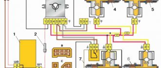
Diagram of the standard crankcase ventilation system
The crankcase ventilation system of VAZ engines consists of two circuits that operate at different load modes and speeds:
- The small ventilation circuit is connected to the valve cover and the intake manifold (behind the throttle body). This connection diagram provides intensive crankcase ventilation due to the vacuum that occurs in the intake manifold when the throttle is closed. To avoid an effect such as hyperventilation, the cross-section of the small circuit is limited by a jet in the cable throttle body with a diameter of 1.7 millimeters. This circuit operates in the region of 800-1500 rpm.
- A large ventilation circuit is connected to the valve cover and the air pipe (in the pre-throttle space). This scheme provides intensive crankcase ventilation at high speeds. The cross section of the large contour is 16-18 millimeters
Examples demonstrating the shortcomings of the standard crankcase ventilation system:
- A car is going down a hill with the gear in gear. In this mode, the engine operates at higher speeds with a reduced load. A high vacuum is created in the crankcase, and a large ventilation circuit is connected, in which there are no control valves. Since both circuits are connected to one volume of the oil trap, a strong vacuum in the crankcase will draw a fresh portion of air bypassing the throttle. The mass air flow sensor will show increased air flow, and the ECU will try to close the throttle. Having realized that this is not possible (it is already closed), the lean mixture will be corrected by increasing the fuel supply (fuel consumption will increase). As a result, the entire internal volume of the engine will work as a parallel receiver of very significant volume, connected to the intake, bypassing the throttle. It is this volume that will interfere with the formation of a high-quality mixture.
- A car in a traffic jam drives under tension with additional consumers (for example, the air conditioner is on). The compressor clutch is connected, the load increases abruptly. The engine does not have enough air, it begins to pull it from the crankcase, bypassing the throttle. But the ECU is also aware of the clutch engagement and also supplies more air by opening the throttle. The vacuum drops sharply, the vacuum brake booster (VBR) does not have enough strength to hold the car. Leap forward. The ECU sees an increase in oxygen and closes the throttle. A sharp increase in vacuum, VUT seizes. The car jerks, the transmission hits. And so on ad infinitum.
As a result, in both cases, when the engine is running, speed jumps occur and the engine choke under the load. Jerking and vibration are possible on manual transmissions, automatic transmissions and automatic transmissions. To eliminate these shortcomings, it is proposed to modify the design according to one of the presented schemes.
What internal and external factors affect ventilation wear
Clogged hoses cause the seals to squeeze out. Due to the increased pressure, oil flows through the crankshaft and valve cover seals. The probes may fly out.
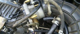
Worn out ventilation system
When hoses are damaged, air may be drawn in. This leads to a decrease in dynamic characteristics. The valve sends gases to the engine, and carbon deposits along with oil clog the throttle valve. During repairs, the brackets cannot be removed; due to them, the hose is fixed at an angle. Otherwise, the condensate formed in winter will not be able to drain, but will freeze and clog the line.
Schemes for upgrading the crankcase ventilation system
Schemes for modifying the crankcase ventilation system, as well as a description, are provided by IgorRV.
For LADA cars with manual transmission and AMT (“robot”), scheme No. 1 “Crankcase ventilation scheme with PCV valve for E-GAS and cable throttle” is suitable:
It is necessary to install a PCV valve (article 94580183, price about 400 rubles) from a foreign car into the small crankcase ventilation circuit. When connecting the PCV valve to a small circuit on an E-GAS, use a new hose (petrol-oil-resistant 8 mm without fabric reinforcement). On a cable choke, connect to the receiver, not to the choke.
As a result, the valve will shut off the circuits in transient modes, which will allow:
- Accept the load without jerking or dropping engine speed (for example, when the compressor is running, heated windows, seats, etc.).
- Reduce vibration load at idle
- Increase traction from the bottom (noted by owners of automatic transmission with VAZ-21126 engine, manual transmission with VAZ-21227, 21126 and 11186 and AMT with VAZ-21127).
- Get a sharper response to the gas pedal and faster shifts (on AMT). Perhaps due to the fact that the valve does not allow the engine to slow down, maintaining a more optimal switching algorithm.
- Reduce oil consumption through ventilation.
The valve replacement period is 40,000 km.
For LADA cars with automatic transmission (Jatco) and AMT (“robot”), scheme No. 2 is suitable:
Description of scheme No. 2: The pressure reducing valve is connected in series to a large ventilation circle. Thus, it regulates the flow of crankcase gases at high speeds and during transient processes. This allows:
- Exercise full control over the flow of crankcase gases between the small and large circuits.
- Improve engine operating mode.
- Reduce vibration load.
- Reduce oil release into ventilation.
For LADA cars with automatic transmission (Jatco) and AMT (“robot”), scheme No. 3 is suitable:
Description of scheme No. 3: To improve the operation of the braking system and facilitate the process of holding the car on the brakes in mode “D”, an “Ejection Pump” was used. Due to the flow of crankcase gases from the small circuit, the vacuum in the tube leading to the vacuum booster increases. This happens at low speeds, which is very helpful when driving in traffic jams. Keeping your foot on the brake all the time is not very easy, but this pump makes the task easier.
- Getting rid of vibrations, failures, transmission shocks.
- The engine begins to operate more calmly and softly.
- The force on the brake pedal becomes less.
- The air conditioner turns on almost imperceptibly.
- ejection pump (article 10793 VIKA, price 546 rubles);
- pressure reducing valve (article 1117701500 JP GROUP, 422 rubles);
- PCV valve (article 94580183 GENERAL MOTORS, 400 rubles);
- clamps (about 10 pieces, 600 rubles);
- thin, petrol-resistant 8 mm hose 50 cm (100 rubles);
- standard ventilation pipe.
Installation example on video:
By the way, there are other ways to modify the crankcase ventilation system. Are you ready for such modernizations? Let us remind you that modification of the ignition system (installation of capacitor ignition coils in the harness) is also common among owners of LADA cars.
Video
Tools:
- Open-end wrench 10 mm
- Open-end wrench 13 mm
- Open-end wrench 17 mm
- Medium Phillips screwdriver
Parts and consumables:
- Gasoline/kerosene
- Rags
- Sealant
- Automotive compressor
- Cylinder head cover gasket (if replacement is needed) -2108-1003270-10
Read more: KAMAZ air filter element
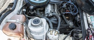
The crankcase ventilation system of the VAZ Lada Kalina 1118 tends to accumulate tarry deposits from crankcase gases, which make it difficult to remove these gases into the engine cylinders for combustion. Because of this, the gas pressure inside the engine increases and oil leaks through the seals appear. We recommend cleaning the crankcase ventilation system before each oil change.
1. Remove the decorative plastic engine cover.
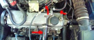
2. Loosen the clamp and disconnect the hose of the large branch of the crankcase ventilation system from the air supply pipe.
3. Disconnect the second end of the large crankcase ventilation system hose from the fitting on the cylinder head cover and remove the hose.
4. Similarly, remove the hose of the small branch of the crankcase ventilation system by disconnecting it from the fittings of the throttle assembly and the cylinder head cover.
5. Remove the supply hose of the crankcase ventilation system by disconnecting it from the fittings of the cylinder block and the cylinder head cover.
6. Rinse the hoses with gasoline or kerosene, blow with compressed air and dry. Clean the holes in the fittings and pipes for connecting the hoses.
7. Unscrew the two fastening nuts and remove the cylinder head cover.
8. Unscrew the long 1 and short 2 bolts securing the oil separator from the inside of the cylinder head cover and remove the washers.
9. Remove the oil separator housing.
10. Remove the mesh pack from the cylinder head cover.
11. Thoroughly rinse the screens, oil separator housing and cylinder head cover with kerosene.
12. Turn the meshes in the bag so that they are oriented in the same way, and install the bag in the lid so that on one side it rests against the protrusions in the lid, and on the other side you can see the hole for the bolt that secures the oil separator of the VAZ Lada Kalina 1118.
13. Install the oil separator housing and tighten its mounting bolts.
14. Check the condition of the cylinder head cover gasket and replace if necessary.
15. The hoses of the crankcase ventilation system and the cylinder head cover of the VAZ Lada Kalina 1118 are installed in the reverse order of removal.
The article is missing:
- Photo of the instrument
- Photos of parts and consumables
- High-quality photos of repairs
If, while operating a LADA car, you notice that during load (when the air conditioner is running, the heating is on, etc.) in a traffic jam, the engine begins to operate unstably (troits, pulls poorly, etc.), perhaps the reason lies in the ventilation system crankcase The article proposes to solve the problem by installing a PCV valve from a foreign car.
Improved crankcase ventilation. Useful improvements
It is worth noting the fact that modification of the crankcase ventilation allows us to solve some problems with excessive release of oil condensate and other problems with the functionality of the unit in question. There may be several reasons for the accumulation of oil on the walls of the intake system of the power unit. The main contributing factors are related to the absence of a hydraulic intake, aimed at the unhindered flow of oil into the cylinder cavity according to the reverse flow pattern.
In addition, the appearance of the presented malfunction is affected by a small number of in-line turns, which does not allow the emitted gases to gain the required speed. The design is able to filter out large particles of the product, but small components are ignored due to flaws in the base.
see also
- Roof ventilation system
- DIY heat exchanger for ventilation
- The best kitchen hoods with ventilation outlet
- Blowing from the ventilation
- Supply ventilation for office
- Ventilation in an apartment with plastic windows
- Natural ventilation in the chicken coop
- Ventilation for garage
- Controllers for ventilation and air conditioning
- Supply and exhaust ventilation with heat recovery
- Crankcase ventilation system VAZ 2112 16 valves
First option
Modification of crankcase ventilation can be done in several ways. For example, on the M50 you can install an oil separator unit from the M52 model. However. This manipulation does not solve the problem of having a container for draining liquid, external aesthetics and the need to place a water seal.
One of the current solutions to the problem under consideration would be the installation of a HEPA filter, which contains wire and filament components that make it possible to adjust as accurately as possible the amount of gases released. The inside of the oil separator is filled with copper wire wool. In the standard version, the packing should protrude slightly beyond the base of the lid. The corrugated inlet and throttle assembly are thoroughly wiped. After performing the manipulations, the element is checked by mechanical purging for changes in air flow.
The second method of upgrading crankcase ventilation
The meaning of the following is to transfer the small ventilation circuit from the throttle part to the receiver, which helps reduce differences when switching modes. To complete this design, you will need to perform the following manipulations:
- The thin crankcase ventilation hose is disconnected from the throttle;
- The free end is connected to the free inlet fitting on the receiver, with preliminary removal of the plug;
Alternative options
The next version of the improvement involves installing a hose with a small diameter into the crankcase ventilation circuit of the EPK valve of the “Cascade” model. In idle mode, the valve for standard exhaust gas outlet should be opened. Considering the fact that when installing the system in question, the supply of harmful impurities through the throttle valve stops due to the circuit opening. This is very important in the case of a transition of the engine operating mode from idle to light loads, when a lean air-fuel mixture is categorically unacceptable. Ventilation is carried out through the entire line, including the carburetor unit.
After further replacing the durite with a hose from the vacuum ignition advance device, it is reasonable to increase the diameter of the main jet of the first combustion chamber or simply reduce the input fuel flow to 4.5 mm. The scheme under consideration was tested on a model of the domestic VAZ 2101. At the same time, the following positive aspects became noticeable:
- The pedal drop during acceleration has disappeared;
- The engine's operation became smooth;
- There are no intermittent oscillations at idle.
Using the recommendations of specialists and folk craftsmen, it is possible to independently correct a number of malfunctions and shortcomings of a personal vehicle. Modification of the crankcase ventilation is appropriate for some vehicle equipment, regardless of the year of manufacture and country of manufacture. This problem is most pressing for domestic cars with carburetor engines.
Fuel economy
For those who are sick of the failure at the beginning of the pedal stroke on the DAAZ-2108!
This modification allows you to optimize the operation of the transition system of the 1st chamber and the entire carburetor as a whole, provided that it is in good condition and there are no air leaks at the joints, but it is not possible to achieve its normal operation.
As practice has shown, replacing the XX jet with a larger one does not eliminate the failure at the start. Replacing the accelerator cam No. 7 with No. 4 improved the acceleration dynamics, but the failure remained as before.
Then, analyzing the operation of my carburetor, I came to the conclusion that the crankcase ventilation channel located next to the XX channel is to blame, which in turn does not allow the transition system to work normally, depleting the mixture at a time when the GDS has not yet had time to join the process of mixture formation.
It seemed that the only solution was to plug the channel, but it immediately turned out that the XX does not have enough air (albeit dirty) which comes precisely through this very appendix.
The decision has come on its own. The essence of the modification comes down to installing a thin crankcase ventilation hose of the electro-pneumatic valve from the CASCADE system (Ozone carburetor with EPHH) into the gap and connecting it to the contact on the throttle lever of the 1st chamber (via the EPHH control unit).
At XX, the valve is open (the circuit is closed), and crankcase gases pass under the carburetor as usual.
But when the D/Z opens, it closes (the circuit is open) and blocks the path of gases, thereby stopping the mixing of this muck into the air-fuel mixture at the most crucial moment - the transition from idle to light loads and higher, when depletion of the mixture is not permissible. Ventilation is carried out through the main line, through the entire carburetor.
From the valve we connect two wires to terminals 4 and 5 of the EPHH block.
We replace the durite with a hose from a vacuum ignition advance machine (VAZ 2101). Since in all modes except XX, the mixture became slightly richer, it probably makes sense to increase the diameter of the main air jet of the 1st chamber, but I simply reduced the fuel level in the float chamber - 4.5 mm, instead of 1 mm (4.5 original Tauride gap A).
- the failure is gone;
- the engine has become more elastic;
- There are no twitches at low throttle, especially noticeable in 2nd gear.
Scheme of modification of the crankcase ventilation tract
Taken from the Tavria Club forum, author Punker.
Crankcase ventilation systems
Not all owners know about the existence, and even more so the design of this system in car engines. Because mainly because it usually makes itself known after many years of operation, when the engine begins to require repair. And it’s true that it took shape in the system recently, when instead of a tube with a partition through which gases from the crankcase came directly out, they began to use various devices that prevent air pollution and save oil. As a result, it began to noticeably influence the operation of the engine, and therefore demand attention, which it is denied, most often out of ignorance.
The proposed material prepared by engineer E. Maslennikov will help fill this gap.
When the engine is running, some of the gases from the cylinders penetrate through the piston ring seals into the crankcase. Here they increase pressure, displacing oil out through the joints of parts sealed with gaskets and seals, and also negatively affect the properties of the oil. The amount of these gases, called crankcase gases, depends on the design features and quality of surface treatment, as well as on the wear of parts of the cylinder-piston group, the load on the engine or, which is the same, the degree of opening of the carburetor throttle valve. The pattern of crankcase gas breakthrough depending on the last two factors is shown in Fig. 1.
Rice. 1. Dependence of the amount of gases breaking into the crankcase M, kg (%): a) on the load; b) from wear of parts of the cylinder-piston group (CPG). Points: 1 – after engine running-in; 2 – at the end of the service life of the CPG parts.
According to the current requirements for gasoline engines with a displacement of up to 2 liters, the maximum amount of breakthrough gases in a new engine should not exceed 2,000 l/h (point 1
in Fig. 1, b). As the gap in the piston ring locks increases, this value increases and, at the border of normal wear of parts of the cylinder-piston group, can reach 150% of the original.
As studies show, almost 3/4 of crankcase gases consist of the combustible mixture that entered the cylinders and broke into the crankcase during compression and combustion, and 1/4 of exhaust gases. Therefore, they contain a lot of fuel (hydrocarbons with the general formula CH), toxic combustion products (carbon monoxide - CO, nitrogen oxides), as well as water vapor, carbon dioxide, particulate matter and some other components. Moreover, crankcase gases contain several times more toxic substances than car exhaust gases.
Many of these components actively affect the oil, causing it to oxidize. And water vapor, combining with nitrogen oxides, forms alkalis and acids, which, when they get on the surface of engine parts, cause corrosion and intense wear. In addition, water vapor plays a significant role in the formation of sediments in the engine lubrication system (this process is described in more detail in the article “How you lubricate is how you drive”).
In order to minimize the impact of crankcase gases on oil quality and engine wear, as well as to stop oil leakage under the influence of increased pressure in the crankcase, a set of devices called the crankcase ventilation system was created. It is designed to ensure the complete removal of gases penetrating into the engine crankcase, to maintain a pressure close to atmospheric in it, in order to prevent oil squeezing out in case of high pressure or suction of air contaminated with dust and moisture into the crankcase - in case of low pressure; contribute to the preservation of the physico-chemical properties of lubricating oil; prevent oil carryover with sucked crankcase gases.
What is this system? Let's consider it using the example of development in domestic passenger car engines.
In the 50s, open supply and exhaust systems were used, as in Volga engines of models “21” and “22” and their modifications. Gases are removed in this system due to the vacuum created by the air flow near the end of the exhaust tube while the car is moving, and when the engine is idling - due to the difference in atmospheric pressure and pressure in the crankcase.
The disadvantages of such a system are poor gas suction when the engine is idling, environmental pollution with highly toxic crankcase gases and oil removed from the crankcase, high oil consumption, as well as moisture entering the crankcase through the ventilation system.
The emergence of motor oils with more stable properties, as well as the legal ban on the use of open systems, led to the creation of a closed exhaust system. It differs from the previous one in that the exhaust tube is not vented into the atmosphere, but into the air entry zone into the inertial oil filter of the engine power supply system, and also in the absence of purging of the crankcase space with air. In this system, gases are removed due to ejection that occurs when washing the pipe cut 8
the flow of air intake from the engine.
Mixing with it, the gases pass through the air filter 10
, where oil droplets, condensed water vapor, solid particles of combustion products, etc. are separated from them.
Such a system was used in the Moskvich-407 and 408 engines, as well as in the air-cooled engine for the Cossacks.
It made it possible to completely eliminate the release of harmful gases into the environment, as well as those negative phenomena that were associated with purging the crankcase with air, and to somewhat reduce the amount of oil carried away from the engine crankcase. In addition, the intensity of crankcase gas suction in this system increases with increasing engine shaft speed, which basically coincides with the pattern of gas breakthrough into the crankcase.
The advent of dry air purifiers with a replaceable paper element in the late 60s required modernization of the exhaust ventilation system. This was explained by the fact that crankcase gases, saturated with oil mist, passing through the filter element, quickly contaminated it. Therefore, the draft tube was moved to the area between the element and the carburetor. And so that the oil, settling on the walls of the air channels in the carburetor jets, does not disturb its regulation, highly efficient oil separators were introduced into the system, from which the oil returns to the crankcase. An example is the crankcase ventilation system in the UZAM-412 engine of the Moskvich-412.
Rice. 2. Crankcase ventilation in the Moskvich-412 engine: 1 – filter element; 2 and 4 – pipes; 3 – hose for sampling gases from the crankcase; 5 – annular cavity of the air cleaner for sampling gases from the crankcase; 6 – carburetor; 7 – inlet pipeline.
However, it also retains a significant drawback, namely that at low air flow rates corresponding to engine operation at idle or at low loads, the suction of gases practically stops, causing a slight increase in pressure in the crankcase. A closed combined system solved this problem. It was based on the previous one, and to remove gases under unfavorable conditions, an additional branch was introduced with access to the throttle space. This required a special device that regulates the intensity of suction, since when the load decreases, the breakthrough of gases into the crankcase decreases, and the intensity of their suction increases with increasing vacuum in the throttle space. Such a system can be seen in the UZAM-412 engine installed on the Moskvich-2140, and in VAZ engines of the 2101, 21011, 2103, 2105, 2106 models. Here the intensity of gas suction is controlled by the spool 1
, mounted on the throttle valve axis in the first chamber.
When the engine is idling or at low loads, crankcase gases pass through calibrated hole 2
, and as the load increases, through a bypass channel opened by the spool. Subsequently, with increasing vacuum in the area between the air cleaner filter element and the carburetor, the bulk of the gas is sucked out through the main branch.
Rice. 3. Scheme of crankcase ventilation in the VAZ-2105 engine: 1 – spool; 2 – calibrated hole; 3 – intake manifold; 4 – throttle valve; 5 – hose for venting gases into the throttle body; 6 – carburetor; 7 – filter filter element; 8 – suction pipe for crankcase ventilation; 9 – flame arrester; 10 – exhaust hose; 11 – oil separator cover; 12 – oil separator; 13 – oil separator drain pipe.
Oil separated from crankcase gases flows down the drain pipe 13
. The breakthrough of flame into the engine crankcase during flashes in the carburetor is prevented by a flame arrester installed on the hose.
Rice. 4. Scheme of crankcase ventilation in the VAZ-2108 engine: 1 – intake pipe; 2 – tube for removing crankcase gases into the throttle space of the carburetor; 3 – carburetor; 4 – air filter; 5 – upper exhaust hose for crankcase ventilation; 6 – oil separator mesh; 7 – cylinder head cover; 8 – oil separator housing; 9 – lower exhaust hose for crankcase ventilation; 10 – oil level indicator; 11 – fitting.
The introduction of a spool device, unfortunately, complicated the system and reduced its reliability, since a moving part appeared, and also increased the cost of the carburetor. Therefore, it was later abandoned, and the newly developed VAZ-2108 and 2109 engines, as well as UZAM-331.10 for Moskvich-2141, have gases from the additional branch 2
exit through the carburetor fitting, which has a calibrated hole that limits the amount of gases sucked out. Due to this, ventilation has virtually no effect on the vacuum in the intake pipe at idle. In addition, the VAZ-2108 engine uses a new, more efficient mesh oil separator, which simultaneously serves as a flame arrester.
Now, having familiarized ourselves with the structure and operation of various ventilation systems, let’s move on to their operation. What should you pay attention to? Since there are no moving parts in the system (with the exception of systems with a spool device), and crankcase gases are suctioned due to the vacuum in the engine intake tract, it is probably necessary first of all to ensure the tightness of the system. Therefore, it is useful to regularly check the tightness of the connection of the hoses with the fittings, as well as the oil separator cover with the housing (for all VAZ engines, with the exception of “2108”). In addition, during the operation of the car, precipitation falls out of the oil, and deposits appear on engine parts, including the ventilation system. As a result, the flow areas of channels and hoses are reduced, which is why the amount of gases sucked out decreases until ventilation stops completely.
To eliminate this malfunction, the system must be periodically disassembled, washed and cleared of deposits from parts. In this case, special attention should be paid to the small-diameter channels located in the carburetor, through which crankcase gases are supplied to the spool device and discharged from it into the throttle space. If necessary, the calibrated hole in the spool or in the carburetor fitting can be cleaned with a wooden stick. To wash the parts of the ventilation system, you can use kerosene or gasoline, and to wash the spool device, fitting and carburetor channels - acetone. The frequency of system maintenance is different for each engine model, indicated in the vehicle’s operating instructions.
When servicing the crankcase ventilation system of VAZ engines, it is also necessary to flush the flame arrester, disassemble the oil separator and clean its parts. To do this, for VAZ-2101, “21011”, “2103”, “2105”, “2106” engines, simply remove the cover by unscrewing the nut. On the VAZ-2108 engine, remove the cylinder head cover, then unscrew the two bolts securing the oil separator housing to it, and dismantle the housing and mesh. In UZAM-412 (Moskvich-412) engines the oil separator is non-separable. It is made as one piece with the oil filler plug, and its cleaning consists of flushing with kerosene or gasoline.
Finally, I would like to dwell on two defects that car enthusiasts often associate with the performance of the crankcase ventilation system.
Owners of some cars with a UZAM-412 engine complain about a large amount of oil entering the air filter housing through the ventilation system, which leads to rapid oiling of the filter element, air channels and carburetor jets. The reasons are due to loose connections. First, check how the oil separator housing fits against the plate attached to the cylinder head cover. To do this, remove the cover and, by pressing your finger through the hole in the plate onto the body, make sure that it is well pressed by the spring. If everything is in order here, then the cause, as a rule, is an increased oil level in the crankcase. Don't be complacent if the dipstick marks normal. Check whether its guide tube with conical thread is screwed in completely. When trying to screw it in, do not use too much force to avoid breaking it. If you cannot tighten the tube, do not add oil 3-4 mm to the top mark on the oil dipstick.
Some Cossacks experience oil leakage through the crankshaft seals after 70–80 thousand kilometers. If replacing the oil seals with new ones does not bring the desired result, car enthusiasts correctly associate this with an increase in pressure in the crankcase. But the reason causing this increase is often mistakenly seen as a deterioration in the suction of crankcase gases by the ventilation system. To improve its performance, some, without further ado, disconnect the crankcase gas suction hose from the air filter housing, thus turning the system into an open one, while others begin to improve it in order to increase productivity. In fact, the increase in pressure in the engine crankcase and, as a result, oil leakage through the crankshaft seal is caused not by a deterioration in the performance of the ventilation system (if, of course, it is working properly), but by excessive wear of the parts of the cylinder-piston group - compression piston rings, cylinders and pistons.
In conclusion, I once again urge all motorists to keep the crankcase ventilation system in order. Throwing untreated crankcase gases into the atmosphere, as would-be car enthusiasts do (perhaps unknowingly) by disconnecting the hose from the air cleaner and lowering it under the car (fortunately it is not visible, and the oil is inexpensive) means poisoning the air and the earth. This is a crime today!
Possible heater malfunctions
Your stove is not working or is not heating well. Look for the cause of the problem. The fan does not work or the heater radiator is leaking - obvious breakdowns that occur at any time.
Stove control unit:
- The engine was warmed up, but warm air did not enter the cabin.
- The damper drive cables may have come off. The only solution is to remove the console.
Dampers. Partially open or close. The rubber seal has come off in the air duct or foreign objects have gotten into it.
Antifreeze circulation. Start the engine and check the level in the expansion tank, and also check for any disturbances in the normal flow of antifreeze. Possible reasons:
- Pump. Cannot be repaired, only replaced.
- The cooling system is clogged. Clean or rinse.
Checking the thermostat. Warm up the engine to 75°C. If the upper pipe is cold, then the thermostat does not work correctly and does not allow coolant to move in a large circle. Replace the device.
Airlock. Remove the plug from the vehicle's engine cooling system.
Temperature sensor. Constantly blowing cold or hot air. If cleaning the contacts does not help, then replace the non-working temperature sensor.
Air filter. If the air flow is weak and there is no desired temperature, then replace the filter. Be sure to check the heater resistor, which controls the rotation of the fan and is located under the glove compartment.
Electric fan. The device does not turn on regardless of the selected mode. Check the fuse that controls operation. If the fan is turned on and its operation is accompanied by strange sounds, clean or replace it.
Dampers. It is difficult to determine the breakdown unless you replace the dampers themselves.
The cause of a heater malfunction may be a depressurization of the car's engine cooling system. The types of breakdowns described above cause malfunctions in the operation of the Lada Kalina car's stove. Such breakdowns do not require special knowledge; they are easy to understand and repair.
Crankcase gases - we do modernization
There is something wrong with these environmental gadgets. They always worsen the quality of the mixture, reduce power, accelerate oil aging, reduce engine life, etc. So I decided to get rid of the last lotion, crankcase ventilation. There will be ventilation, but not into the engine.
The engine, like us, needs clean air, and the cleaner the air, the longer we stay healthy, and the same with the engine. Preventing a collective farm from releasing gases into the exhaust is costly and new problems arise. You just need to send them into the atmosphere through a carbon dioxide filter.
Crankcase gas filter. First, I modernized the breather, cut off the extra fittings and plugged the holes with epoxylin. I plugged the second tube from the oil separator by screwing a bolt into it. If the breather had been new, they wouldn’t have mocked it so much; one fitting on it was already broken.
Reworked breather. I cut off a tube that looked like a slingshot. Yes, it was a shame to cut it, but it didn’t take long to restore it; insert a spacer made of plastic tube into the place of the cuts.
The filter was installed on the rest of the tube.
And this is how it looks from the outside. The engine starts and runs great. A light smoke comes out of this filter, not even smoke but steam.
No smell gets into the cabin. I want to say that the breather is designed in such a way that there should not be a vacuum in the crankcase, or rather, it should be very insignificant, just to pick up steam. And the fact that I brought the ventilation into the atmosphere will have no effect on him. That's all.