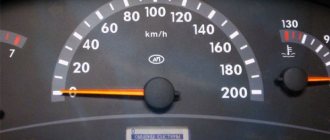
Indicator for low beam VAZ 2110.
It so happens that old-style cars have an indicator for turning on the headlights, but there is no indicator for the low beam, which is a clear inconvenience. You should consider possible options for improving this shortcoming and getting an indicator for low beam.
Option #1
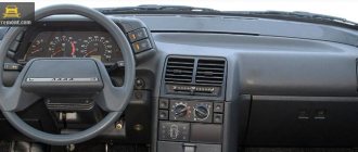
The lamp on the instrument panel lights up when the side lights are turned on, and remains on when the low beam is turned on. But you need to make it light up when you turn on the low beam. To do this you need to perform a number of actions:
– there is a light bulb on the back of the instrument panel; you need to run a plus wire to it. – one edge of the wire is connected to the low beam contact, and the second must be soldered to the base leg. – to prevent the light on the dashboard from lighting up when the side lights come on, you should break off the contact located on the socket.
Option No. 2
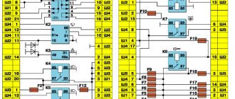
It is not necessary to remove the dashboard to achieve the desired result. After opening the fuse panel, turn it back towards you. There is block Ш2, we find two wires on the 8th contact and. Using a tester, we find a wire that connects to the dashboard, specifically to block X1-6. We move the found wire to Ш3-1 or Ш3-3.
There is a minus in the options presented above - now the lamp on the instrument panel will not indicate that the side lights are still on. If there is a need, then you should use another reminder to turn off the parking lights, or use other bulbs for the low beam indicator, say, a choke indicator, but this is not used in cars with an injector.
Option #3
The button that turns on the side lights and low beam has a built-in indicator. Most often it goes unnoticed. With the help of an LED light bulb it is possible to duplicate it. To do this you need:
1. Screw an LED into the pre-made hole in the button. 2. From the standard backlight button, connect the plus wire to the LED.
The standard light on the instrument panel comes on when the side lights are turned on, but the button indicator does not light up. If you turn on the low beam, the light will remain on. The button lights up with a built-in LED that is bright enough to be noticed.
It happens that the button that turns on the side lights and low beam is not fully installed in the dashboard, in which case the wires to the button can be routed without using a block. Use daytime running lights or specific controls if you always leave your low beams on.
Method number 2
This method involves the use of non-ferrous metal shavings as a conductive element. Also, to repair the thread, we will need a transparent varnish (it is advisable to use a thick one, like for nails).
Mix the shavings with a brush and apply to a strip previously sealed with tape, as in the previous case. After an hour, the varnish will completely dry. The method is quite old. It is not always possible to connect damaged contacts as needed. Therefore, if it is possible to buy conductive glue, it is better to use the first method. It will be much faster, easier and more reliable. The cost of a 10-gram tube with this composition is 78 rubles. This volume is more than enough to repair several damaged heating threads.
Illumination of buttons on the VAZ 2110 panel
The first thing to do is remove the button itself. Let's analyze it. To do this, pull the body and the moving part in different directions. Great, now we see the incandescent lamp in the housing. Then it all depends on your dexterity: you can remove it from there at this stage (I didn’t succeed). If the efforts do not yield results, we analyze further. To do this, use a screwdriver or a knife to pry off the latches on one side and the other.
The switch mechanism was exposed before us. Our goal is the black bracket; we pry it with a screwdriver and the mechanism falls apart. This way we get the opportunity to freely remove the lamp, for example, with tweezers with electrical tape on its ends for better adhesion to the lamp. Or between pins 6 and 7 there is a small hole through which a needle can fit to press out the lamp
Now it all depends on your imagination and means. For example, you can buy a ready-made LED lamp of any color. I used my own design (my first experience in soldering SMD components =)). In the case of LEDs, please note that “+” is contact No. 6, and “-” is contact No. 7 (we look at the back of the case where the block with wires is inserted).
How to repair the conductive layer? Method No. 1
You can do this yourself. To do this, you do not need to dismantle the glass. All you need is to purchase a special conductive paste (available in auto stores or on the market) and apply it to the damaged area. It is important to prepare it carefully. To do this, carefully clean the varnish from the surface and degrease the area with alcohol (use a piece of soft rag). Next, we clean the ends of the damaged threads. We apply adhesive tape or electrical tape to its upper and lower parts so that there is a small gap (no wider than the thread itself). We apply a special adhesive into it. After a day, the composition will completely dry out. Next, you can remove the remaining tape and check the system for functionality. If the heating works only partially, it means that the break occurred in several places. Find the second place where the thread is damaged and treat it with a conductive compound using a similar principle. That's all. We will also consider the old-fashioned method of repairing threads.
Low beam button illumination VAZ 2110 (European panel)
[td] All owners of a 'ten' with a Europanel are familiar with the situation when the indicator in the button does not light up when the low beam is turned on. As a result, checking every time whether the low beam is on or not is not convenient. Let's look at how you can modify the low beam button with your own hands.
Method No. 1 You will need: an LED (in our case, white 1.2V), a green filter (can be taken from the fog light button), a flat-head screwdriver, a utility knife, some wires and a soldering iron.
We remove the two buttons (turn on the side lights and low beam headlights), and carefully disassemble them. Illumination of the low beam button is not provided by the manufacturer, so to install a light filter in the button, you will first need to cut out the plug.
Then we lay two wires through the button, which we solder to a pre-installed LED. Don't forget about the resistance for the LED, which is more convenient to place behind the button.
Connecting the button backlight:
- We hook the mass onto the body.
- We connect the 'Plus' to the mounting block, contact Ш3-1 or Ш3-3 (the plus appears here after the ignition is turned on).
All that remains is to assemble the button in the reverse order and check the operation of the indication.
Method No. 2 After disassembling the button, we see:
We make the contacts into the plug from a female connector, onto which we extend the wires. Then remove the top light bulb with copper contacts on the back side:
- - Marked in red where it was.
- — Green marks where it was moved along with the light bulb.
- — Yellow and white — positive contacts for LEDs.
- — Green circles are the location of the previously prepared female connectors with the wire.
- — Red circles are the connection point to the circuit.
- — The green wire is 'plus'.
- - Brown - 'mass'.
By the way, on the old-style dashboard there are button indicators, but they are blocked by the steering wheel rim, so duplicate LEDs are installed.
Smooth turning on and off of LEDs: ignition circuits
In some cases, it is necessary to implement a circuit for smoothly turning on or off an LED. This solution is especially in demand in organizing design solutions.
To implement the plan, there are two solutions. The first is to buy a ready-made ignition unit in a store. The second is making a block with your own hands.
In the article, we will find out why it is worth resorting to the second option, and also analyze the most popular schemes.
Buy or make it yourself?
If you need it urgently or don’t have the desire or time to assemble a block for smooth switching on of LEDs with your own hands, then you can buy a ready-made device in a store. The only negative is the price. The cost of some products, depending on the parameters and manufacturer, can exceed several times the cost of a device made by yourself.
If you have the time and especially the desire, then you should pay attention to long-developed and time-tested schemes for smoothly turning on and off LEDs.
What do you need
In order to assemble a circuit for smooth ignition of LEDs, first of all, you will need a small set of radio amateurs, both skills and tools:
- soldering iron and solder;
- textolite for the board;
- body of the future device;
- a set of semiconductor devices (resistors, transistors, capacitors, LEDs, diodes, etc.);
- desire and time;
As you can see from the list, nothing special or complicated is required.
The Basics of Soft Start
Let's start with the basics and remember what an RC circuit is and how it is related to the smooth ignition and decay of the LED. Look at the diagram.
It contains only three components:
- R – resistor;
- C – capacitor;
- HL1 – backlight (LED).
The first two components make up the RC circuit (the product of resistance and capacitance). Increasing the resistance R and capacitance C of the capacitor increases the ignition time of the LED. When decreasing, the opposite is true.
We will not delve into the basics of electronics and consider how physical processes (more precisely, current) occur in this circuit. It is enough to know that it underlies the operation of all smooth ignition and extinction devices.
The considered principle of RC delay underlies all solutions for smooth turning on and off of LEDs.
Schemes for smooth switching on and off of LEDs
There is no point in disassembling cumbersome circuits, because... Most problems can be solved by simple devices operating on elementary circuits. Let's consider one of these schemes for smoothly turning on and off LEDs. Despite its simplicity, it has a number of advantages, high reliability and low cost.
Consists of the following parts:
- VT1 – field effect transistor IRF540;
- C1 – capacitor with a capacity of 220 mF and a voltage of 16V;
- R1, R2, R3 – resistors with a nominal value of 10, 22, 40 kOm, respectively;
- LED – light-emitting diode.
Operates from a voltage of 12 Volts according to the following algorithm:
- When the circuit is connected to the power circuit, current flows through R2.
- At this time, C1 gains capacity (charges), which ensures the gradual opening of the field switch VT
- Increasing gate current (pin 1) flows through R1, and causes the field drain VT to gradually open
- The current goes to the source of the same field switch VT1 and then to the LED.
- The LED gradually increases its light emission.
The LED dims when the power is removed. The principle is the opposite. After turning off the power, capacitor C1 begins to gradually transfer its capacitance to resistances R1 and R2.
The discharge rate, and thus the smooth decay rate of the LED, can be adjusted by the nominal resistance R3. Experiment to understand how the rating affects the speed of LED ignition and decay. The principle is the following - higher resistance, slower attenuation, and vice versa.
The main element is the field-effect n-channel MOSFET transistor IRF540, all other semiconductor devices play an auxiliary role (piping). It is worth noting its important characteristics:
- drain current: up to 23 Amperes;
- polarity: n;
- drain-source voltage: 100 Volts.
More detailed information, including current-voltage characteristics, can be found on the manufacturer’s website in the datasheet.
Improved version with the ability to customize the time
The option discussed above assumes the use of a device without the ability to adjust the ignition time and LED attenuation. And sometimes it is necessary. To implement it, you just need to supplement the circuit with several elements, namely R4, R5 - adjustable resistances. They are designed to implement the function of adjusting the time of complete switching on and switching off the load.
The considered schemes of smooth ignition and decay are perfect for implementing designer lighting in a car (trunk, doors, foot area of front passengers).
Another popular scheme
The second most popular scheme for smoothly turning on and off LEDs is very similar to the two discussed, but they are very different in operating principle. Switching on is controlled by minus.
The circuit has been widely used in places where one part of the contacts is connected to the negative and the other to the positive.
Differences between the scheme and those discussed earlier. The main difference is a different transistor. The field switch must be replaced with a p-channel one (the markings are shown in the diagram below). You need to “turn over” the capacitor, now the plus of the capacitor will go to the source of the transistor. Do not forget, the modified version has power with reverse polarity.
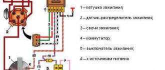
Wiring diagram for fog lights.
According to the factory connection diagram, the fog lights turn on after the headlights are turned on. In this case, you can leave the headlights on with the engine off, which will drain the battery. To prevent this situation, it is better to connect the relay control wire to the terminal from the ignition switch (red in the diagram). But if you want to leave the switch on together with the dimensions, then pin 30 of the relay is best connected to a wire receiving power through the ignition switch. It should be taken into account that the load on the ignition switch will increase.
We recommend watching:
- How to connect LEDs in a circuit
- Diagram of automobile LED lamps
- How to connect an LED to a 12V battery
The LED lamp has stopped lighting
Automatic headlight sensor
Basic Rules
To ensure good visibility in thick fog, it is important to follow these rules:
- Adjust the edge of the light beam so that the light beam is above the horizontal plane.
- Place the flashlight as close to the road as possible. This is necessary to make it easier to adjust the edge of the light beam.
Correctly adjusted headlights guarantee excellent visibility on the road, even in difficult road conditions. To prevent deterioration in the quality of the glow, it is important to monitor the condition of the ceiling. If necessary, polish the surface and remove scratches, as they impair light transmission.
Low beam button illumination VAZ 2110 (European panel)
All owners of a "ten" with a Europanel are familiar with the situation when the indicator in the button does not light up when the low beam is turned on. As a result, checking every time whether the low beam is on or not is not convenient. Let's look at how you can modify the low beam button with your own hands.[/td]
Method No. 1
You will need: an LED (in our case, white 1.2V), a green light filter (can be taken from the fog light button), a flat-head screwdriver, a utility knife, some wires and a soldering iron. We remove the two buttons (turn on the side lights and low beam headlights), and carefully disassemble them. Illumination of the low beam button is not provided by the manufacturer, so to install a light filter in the button, you will first need to cut out the plug.
Then we lay two wires through the button, which we solder to a pre-installed LED. Don't forget about the resistance for the LED, which is more convenient to place behind the button.
Connecting the button backlight:
- We hook the mass onto the body.
- We connect the “plus” to the mounting block, contact Ш3-1 or Ш3-3 (the plus appears here after the ignition is turned on).
All that remains is to assemble the button in the reverse order and check the operation of the indication.
Method No. 2
After disassembling the button, we see:
- — The red circle is the contacts of the size lamp
- - Green circle - where to insert the lamp with contacts
- — Diamonds — output contacts in the plug.
We make the contacts into the plug from a female connector, onto which we extend the wires. Then we remove the top light bulb with copper contacts on the back side: Further according to the diagram:
- - Marked in red where it was.
- — Green marks where it was moved along with the light bulb.
- — Yellow and white — positive contacts for LEDs.
- - Green circles - the location of the previously prepared female connectors with the wire.
- — Red circles are the connection point to the circuit.
- — The green wire is “plus”.
- - Brown - “mass”.
- Ignition is on.
- Dimensions included.
- Low beam is on.
By the way, on the old-style dashboard there are button indicators, but they are blocked by the steering wheel rim, so duplicate LEDs are installed. Photo source: Key words:
Add a comment
Fog light repair
Repairing fog lights may require the following work:
- Glass replacement.
- Installing a new light bulb.
- Replacing the fog lamp frame after removing the bracket. Such work may be necessary if the coating is damaged.
Before repairs, it is recommended to remove the fog lamp, which requires unscrewing the screws securing it to the bracket. Next, we disassemble the PTF to repair or install a new lampshade.
An extreme case is replacing the fog lights. It has to be resorted to in a situation where the unit does not work fully or the quality of the light beam has deteriorated significantly. During the replacement process, you may need to remove the car's bumper because this is where the headlight plug is located. Once you have access to the lamp mounting location on the bracket, use a special tool to unscrew the socket, then discard the plug and disassemble the projector. If the fog lights do not light up and the unit is completely faulty, install a new part.
In bad weather, the effectiveness of headlights is significantly reduced, which not only makes driving less comfortable, but also affects traffic safety.
The beam of light from the low and high beam headlights reflects raindrops and particles of water vapor during fog, forming a dense white veil.
Fog lights (FFL), which provide a flat and wide horizontal beam of light, will be a real salvation for the driver in such weather conditions.
It spreads along the road, well illuminating the side of the road, improving the visibility of the car itself for drivers of oncoming cars.
Standard PTFs are rarely found in basic car configurations, but if desired, fog lights can always be purchased separately and installed independently. To do this, it is enough to have basic knowledge in the field of electrical engineering and electronics.
This is what the diagram for connecting the PTF button via a relay looks like:
Everything about it is extremely simple and clear.
- From the battery it goes through the fuse to the relay contact (30), and then from contact (85) to the contact of the PTF on/off button.
- There is a minus on the second contact of the button.
- Next, from the relay contact (87), the plus goes to the fog lights.
- A minus (86) is attached to the contact.
Please note that each car model has its own characteristics, so the diagram can be changed.
Basic operating principle of electrical equipment
Note. It should be noted that the general principle of operation of electrical equipment on all VAZ families is identical.
- absolutely all electronic devices of the car are connected according to the principle of a single-wire circuit;
VAZ 2110 wiring diagram
- the car body acts as a negative wire;
- all consumer terminals, together with power sources, have a direct connection to the car body.
Note. All electrical wiring wires have a strictly defined color, which is indicated in the diagram by the first letter of the name of the corresponding word.
The power wire is always marked in red in all diagrams and is designated by the letter “P”, since it supplies power to the positive terminal of the battery.
Car lighting VAZ 2110, VAZ 2111, VAZ 2112
Lighting scheme
Headlights and lighting VAZ 2110, VAZ 2111, VAZ 2112
Removing and installing headlights
Dismantling and assembling headlight unit, replacing lamps VAZ 2110, VAZ 2111, VAZ 2112
Headlight hydraulic corrector
Hydrocorrector of headlights VAZ 2110, VAZ 2111, VAZ 2112
Replacing the hydraulic corrector master cylinder
Removing and installing the main cylinder of the headlight hydraulic corrector VAZ 2110, VAZ 2111, VAZ 2112
Adjusting the headlights
Adjusting the headlights of VAZ 2110, VAZ 2111, VAZ 2112 cars
External and internal lighting
Brake and reverse lamps, interior and trunk lighting of VAZ 2110, VAZ 2111, VAZ 2112
Direction indicators
Direction indicators VAZ 2110, VAZ 2111, VAZ 2112
Fog lights
Replacement of side and fog light of VAZ 2110, VAZ 2111, VAZ 2112
Replacing the side turn signal
Removing and installing the side direction indicator VAZ 2110, VAZ 2111, VAZ 2112
Replacing the reverse light switch
Removing and installing the reverse light switch VAZ 2110, VAZ 2111, VAZ 2112
Replacing reverse and brake lights
Removing and installing a brake light and reverse light for VAZ 2110, VAZ 2111, VAZ 2112
Rear license plate light replacement
Removing and installing the rear license plate lamp for VAZ 2110, VAZ 2111, VAZ 2112
How to properly remove a torpedo on a VAZ-2110 so as not to damage it: step-by-step instructions In the design of a VAZ-2110 car, the torpedo is the most revealing part. Every driver wants to sit in a beautiful and expensive interior while driving. But the factory panel has a moody, angular appearance. This becomes especially noticeable after using the car for a long time, when abrasions and scratches begin to appear on it.
Each driver solves this problem in his own way, some purchase a new factory dashboard, others install a panel from foreign car manufacturers. A beautiful trim from a third-party manufacturer allows you to decorate the interior to the level of a foreign car. Whatever option is chosen, you initially need to know how to remove the dashboard on a VAZ-2110 car in order to install another one.
The material from which the pad is made is much softer than the factory panel and is not surprising at the presence of a grinding noise while the machine is moving.
In most cases, motorists dismantle the standard panel precisely because of grinding and squeaking. There are several options for the updated panel for the VAZ-2110, which differ in their design. The panel is available for sale as a set:
- New version of the panel, significantly different from the factory design.
- Brackets, buttons, instrument panels and air vent inserts.
- Set of wires and block for switch.
- Buttons for low beam, fog lights, dimensions and heating.
- Special plugs that are installed in places where there are no buttons.
Removing the dashboard takes a lot of time, since there are a huge number of wires under it, through which electricity is distributed throughout the cabin. The fastenings on the dashboard of the VAZ-2110 car are fragile, so every action during dismantling must be careful. If the fastenings are damaged, it will be impossible to firmly install the panel in its original place, and squeaks and noise during movement will increase significantly. In most cases, to improve the design there is no need to completely remove the panel; it is enough to dismantle only the upper part, but there are non-standard situations, so the article offers a description of a complete analysis.
Tools
In order to completely remove the housing, you will need:
- a set of keys and screwdrivers;
- marker;
- adhesive based labels.
The main work will involve a 10 mm wrench and a Phillips screwdriver. You will also need a water-based marker, since it washes off easily, it is necessary so as not to mix up the removed parts. This also applies to adhesive labels. There are too many parts and wires, so you shouldn't rely on memory. Stickers and bullet points will help you remember the starting place of all the components.
Preparatory work
Some are satisfied with dismantling without removing the remaining components of the interior, but this takes extra time and complicates the process as a whole. In order not to add more work to yourself, it is recommended to clear the interior for free movement. Strictly observing the sequence, you need to remove:
- armchairs;
- glove box;
- steering wheel;
- disassemble the floor tunnel. To do this, you need to unscrew the screws and move the part back a little.
We dismantle the lower part in the same way. The next step is to remove the glove compartment, after which you should remove the relay and mounting block. As you disassemble, you need to mark all the wires. Particular attention should be paid to the speedometer.
Removing the torpedo step by step
- We find two screws on the central panel on the right and unscrew them. We perform the same action on the other side on the left. After this, carefully remove the shield from both sides.
- Using a flat-head screwdriver, pry off the plug, which is located on the central tunnel. We unscrew the tunnel fastenings located on the sides and behind it. Unscrew the screws holding the central panel.
- This part of the interior can already be removed completely. We see that there is access to the cigarette lighter. We mark the wiring and disconnect it, then remove the cover from the gearbox handle.
- The next step is the air duct. We take the key for 10 and dismantle it. There is access to the central panel, which is held on a mount in the front and rear. Unscrew the screws and remove the panel. After dismantling the central panel, you can move on to the main body of the torpedo.
- The glove compartment was removed in advance, as it interfered with the overall process. All that remains is to disconnect the backlight and unscrew the fastener on which it was held.
- Carefully pry up the air duct with a screwdriver and then remove it. There is still a nut on the dashboard that needs to be unscrewed. Now the panel can be easily removed by lifting it up and slightly pulling it towards you. Now it will easily slide off the stilettos. We take out the plugs, not forgetting to mark them with a marker.
The torpedo has been dismantled and can easily be replaced by installing a new panel from a VAZ-2110 or tuned using a more prestigious panel. Assembly must be done in reverse order.
Controls
1, 29 — internal door opening handle; 2, 28 — handle for adjusting the exterior rear view mirror; 3, 27 — side ventilation grilles; 4, 26 — ventilation grilles for blowing door glass; 5 — external lighting switch key; 6 - plug; 7 — sun visor; 8 — left steering column switch lever; 9 — steering wheel; 10 — instrument panel; 11 — lever of the right steering column switch; 12 — control knob for instrument illumination; 13 — control lamp for turning on the rear fog lights; 14 — switch button for rear fog lights; 15 — control lamp for turning on the heated rear window; 16 — rear window heating switch button; 17 — air distributor damper control lever; 18 — individual lighting lamp; 19 — rear view mirror control key (day-night switch); 20 interior rear view mirror; 21 — central ventilation grilles; 22 — ventilation grille for blowing the windshield; 23 — heater control unit; 24 — hazard warning switch button; 25, 37 — plugs; 30 — glove box cover; 31 — clock; 32 — niche cover; 33 — cigarette lighter; 34 ashtray cover; 35 — display unit of the on-board control system; 36 gear lever; 38 — gas pedal; 39 — socket for connecting a portable lamp; 40 — immobilizer sensor with indicator; 41 — brake pedal; 42 — ignition switch (lock); 43 — clutch pedal; 44 — lever for adjusting the tilt of the steering shaft; 45 — steering wheel pad (horn button); 46 — cover of the mounting block of fuses and relays; 47 — button for opening the cover of the mounting block of fuses and relays; 48 — control knob for hydraulic headlight adjustment; 49 — hood lock drive lever; 50 — button for the electric drive of the trunk door lock;
51 — front left seat heating switch key; 52 — control lamp for turning on the heating of the front left seat; 53, 59 — plugs (on some cars, rear door power window switches are installed in these places); 54 — front left door power window switch key; 55 — parking brake lever; 56 — parking brake lever button; 57 — installation location of the control unit for external rear-view mirrors; 58 — power window switch key for the front right door; 60 — control lamp for turning on the heating of the front right seat; 61 — front right seat heating switch key; 62 — rear ashtray
Source
How to properly remove a torpedo on a VAZ-2110 without damaging it: step-by-step instructions
In the design of the VAZ-2110 car, the torpedo is the most revealing part. Every driver wants to sit in a beautiful and expensive interior while driving. But the factory panel has a moody, angular appearance. This becomes especially noticeable after using the car for a long time, when abrasions and scratches begin to appear on it. Each driver solves this problem in his own way, some purchase a new factory dashboard, others install a panel from foreign car manufacturers. A beautiful trim from a third-party manufacturer allows you to decorate the interior to the level of a foreign car. Whatever option is chosen, you initially need to know how to remove the dashboard on a VAZ-2110 car in order to install another one.
In most cases, motorists dismantle the standard panel precisely because of grinding and squeaking. There are several options for the updated panel for the VAZ-2110, which differ in their design. The panel is available for sale as a set:
- New version of the panel, significantly different from the factory design.
- Brackets, buttons, instrument panels and air vent inserts.
- Set of wires and block for switch.
- Buttons for low beam, fog lights, dimensions and heating.
- Special plugs that are installed in places where there are no buttons.
How to repair the conductive layer? Method No. 1
You can do this yourself. To do this, you do not need to dismantle the glass. All you need is to purchase a special conductive paste (available in auto stores or on the market) and apply it to the damaged area. It is important to prepare it carefully. To do this, carefully clean the varnish from the surface and degrease the area with alcohol (use a piece of soft rag). Next, we clean the ends of the damaged threads. We apply adhesive tape or electrical tape to its upper and lower parts so that there is a small gap (no wider than the thread itself). We apply a special adhesive into it. After a day, the composition will completely dry out. Next, you can remove the remaining tape and check the system for functionality. If the heating works only partially, it means that the break occurred in several places. Find the second place where the thread is damaged and treat it with a conductive compound using a similar principle. That's all. We will also consider the old-fashioned method of repairing threads.
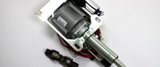
Removal and replacement of VAZ-2110, VAZ-2111 and VAZ-2112 torpedoes
Dear friends, in this material we will tell you in detail and with photographs how to remove the Torpedoun VAZ 2110. VAZ-2111 and VAZ-2112. This is relevant if you are planning to make additional vibration and sound insulation of your car, this way you will get access to the partition of the engine compartment, as well as if you are planning to replace the stock panel with something more aesthetically pleasing, for example, with a Europanel or a panel from a Lada Priora. The process takes about an hour, but there is nothing complicated about it, so let's look at it in detail. First, we remove the steering wheel from its place. We described how this is done in another material.
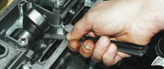
Now remove the side shields, having first unscrewed 2 screws on each side.
For a very long time I wanted to remake the standard button for turning on the side lights and low beam. I was not happy with the fact that when I turn on the low beam, the indicator in the button does not light up (as it turned out, it was simply not installed there from the factory). And checking every time whether the low beam is on or not is not very convenient. So I decided to remake the button and put an indication for turning on the low beam. I bought a simple white (I couldn’t find a green one) 1.2 W diffusion LED and a PTF power button (I took a green filter from it). I disassembled the button and ran two wires through the entire button, soldered an LED to one end without resistance, and then brought out the wires behind the button and soldered the resistance. Then I used a “control” to find the ground and the contact at which voltage appears when the low beam is turned on, and soldered the wires from the LED to these legs. This is what the button looks like from the back with the wires routed and soldered (a little farm-style, but this is the rear view):
Then I removed the light filter from the purchased PTF power button, I also cut out a plug in the standard button (it stood instead of a light filter) and inserted a green light filter into it:
Now, when you turn on the side lights, the button looks like this:
Low beam button illumination VAZ 2110 (European panel)
Method No. 1
We remove the two buttons (turn on the side lights and low beam headlights), and carefully disassemble them. Illumination of the low beam button is not provided by the manufacturer, so to install a light filter in the button, you will first need to cut out the plug.
Then we lay two wires through the button, which we solder to a pre-installed LED. Don't forget about the resistance for the LED, which is more convenient to place behind the button.
Connecting the button backlight:
- We hook the mass onto the body.
- We connect the “plus” to the mounting block, contact Ш3-1 or Ш3-3 (the plus appears here after the ignition is turned on).
All that remains is to assemble the button in the reverse order and check the operation of the indication.
Method No. 2
We make the contacts into the plug from a female connector, onto which we extend the wires. Then remove the top light bulb with copper contacts on the back side:
- Ignition is on.
- Dimensions included.
- Low beam is on.
By the way, on the old-style dashboard there are button indicators, but they are blocked by the steering wheel rim, so duplicate LEDs are installed.
Add a comment
Low beam button illumination VAZ 2110 (European panel)
| All owners of a "ten" with a Europanel are familiar with the situation when the indicator in the button does not light up when the low beam is turned on. As a result, checking every time whether the low beam is on or not is not convenient. Let's look at how you can modify the low beam button with your own hands. |
Method No. 1 You will need: an LED (in our case, white 1.2V), a green filter (can be taken from the fog light button), a flat-head screwdriver, a utility knife, some wires and a soldering iron.
We remove the two buttons (turn on the side lights and low beam headlights), and carefully disassemble them. Illumination of the low beam button is not provided by the manufacturer, so to install a light filter in the button, you will first need to cut out the plug.
Then we lay two wires through the button, which we solder to a pre-installed LED. Don't forget about the resistance for the LED, which is more convenient to place behind the button.
Connecting the button backlight:
All that remains is to assemble the button in the reverse order and check the operation of the indication.
Method No. 2 After disassembling the button, we see:
- — The red circle is the contacts of the size lamp
- - Green circle - where to insert the lamp with contacts
- — Diamonds — output contacts in the plug.
We make the contacts into the plug from a female connector, onto which we extend the wires. Then remove the top light bulb with copper contacts on the back side:
- - Marked in red where it was.
- — Green marks where it was moved along with the light bulb.
- — Yellow and white — positive contacts for LEDs.
- — Green circles are the location of the previously prepared female connectors with the wire.
- — Red circles are the connection point to the circuit.
- — The green wire is 'plus'.
- - Brown - 'mass'.
By the way, on the old-style dashboard there are button indicators, but they are blocked by the steering wheel rim, so duplicate LEDs are installed.