The light in the trunk of the Lada Granta does not work
The technology of betrayal was surprisingly simple - a dull incandescent lamp is removed from the standard socket, wires are soldered to its petals, which happily power the strip with diodes.
Moreover, a hole is made in the standard lampshade through which excess wires are hidden. If anyone doesn’t understand the essence of this confusion: at any moment, the trunk lighting easily returns to its stock state. In the meantime, the diodes are eating up the same five watts of the factory incandescent lamp. But there was much more light from them than there was to it.
(I apologize for the terrible quality of mobile photos)
A few useful things, or what was done.
| MECHANISM |
| View profile |
| Send a private message to MECHANISM |
| Find more posts by MECHANISM |
| Stans |
| View profile |
| Send a private message to Stans |
| Find more posts by Stans |
| Posted by MECHANISM. I left the “+” on the lamp from the dimensions, and shorted the “-” to the limit switch. And as long as the lights are on, everything is fine. I close the trunk and the light goes out. But! If the lights are turned off, but the interior lamp is in the “on the door” position, and the doors are all closed, then both lamps light up, but if you turn off the interior lamp, this disappears. It also disappears if you turn on the dimensions. |
| babai |
| View profile |
| Send a private message to babai |
| Find more posts by babai |
The final idea looks like this: the trunk light is powered by the interior lighting, i.e. I have the “unique” ability to control the trunk lighting, i.e. turn it on to constant light, to automatic when you open a door or trunk, and also turn it off completely. All these modes are on the interior lamp switch. Since I still had a decent supply of wires, the trunk light turned into a carrier, i.e. I can easily take it out, unwind the supply of wires hidden under it, and take it some distance to shine it on. The wiring is laid completely under the casings, and the appearance is not spoiled.
To watch online, click on the video ⤵
Lada Granta FL sedan - problem with interior/glove compartment/trunk lighting (full version) More details
LADA GRANTA FL Lighting in the trunk for the liftback body Read more
Trunk lighting regardless of size! Lada Granta More details
Lada Granta FL trunk light does not work Read more
If you have a problem with interior lighting, look here Read more
Door switch repair on Grant. More details
LADA GRANTA FL The light in the cabin does not work, please contact your dealer for warranty Read more
Lada Granta lamp in the trunk, glove compartment, interior, power windows and trunk button does not work More details
Installation of the trunk button Lada Granta FL 2022 More details
Lada Granta. Trunk light does not work, sedan. More details
Replacing the Granta FL trunk light Read more
The trunk on the Grant does not open for a reason!! More details
Lada Granta - additional rear light for pennies. More details
Lada Kalina trunk light does not go out Read more
Grant trunk locks Read more
The light in the trunk of the Lada Kalina went out, what should I do? More details
Light in the trunk of Lada Granta More details
LADA GRANTA interior lamp does not light up Read more
Glove compartment lighting Grants for 50 rubles without modifications! More details
↑ Solution to the interior lighting problem
The most interesting thing is that on the Internet there are several options for how to return the light to the interior of the Lada Granta, but the most common solution is to “click” the wiper switch when the toggle switch on the lighting lamp is turned on.
It would seem, what do wipers have to do with interior lighting? It is not surprising that the friend treated this advice for solving the problem as a joke or a practical joke. But on occasion I decided to check it out. And..., oh miracle, it worked. The light in the Lada Granta's interior turned on.
Of course, there is not a word mentioned in the documentation about this innovation.
Reason #4: Broken wire
A broken wire may be the reason why the interior lights are not working. Wires that are forced to bend due to their position are especially susceptible to damage. Thus, the wires that run in the trunk lid or in the door often break. This is due to frequent twisting or bending of the wire when opening these housing elements. In theory, the interior lighting wiring does not go into either the door or the trunk, but the general meaning is the same: the wire can be interrupted, transferred, or cut off.
You will need a tester to find the broken wire. Use it to check that it is necessary to make each section of the electrical circuit circular, starting from the ceiling light and ending with the fuse box.
Here are common reasons why an interior light may not be working. However, as mentioned at the beginning of the article, various devices can be included in the cabin lighting scheme. For example, interior lighting control unit, alarm system, on-board control unit, etc. The presence of these devices makes troubleshooting difficult since the cause may be internal to the unit and may also represent an electronics "failure".
You can “calculate” a certain electronic unit that prevents the light from working using the same tester. Simply put, if the voltage on the interior lighting cable enters this unit but does not exit it, there is a power outage inside. It is better to entrust the diagnosis of complex electronic devices to specialists.
Installation of glove compartment lighting Grants
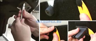
Illumination of the glove compartment can be done using incandescent lamps (we use the standard trunk light for mounting), or using LED strips (we fix them with clamps or glue). We will focus on the first option, but the only difference is in the installation.
It is not necessary to remove the glove compartment, but it is advisable, it will be more convenient to work. First, cut a hole in the back wall of the glove box for the lampshade; a utility knife is suitable for this. We install the lampshade into the cut hole.
In order for the light in the Granta's glove compartment to come on when it is opened, you will need a limit switch. We cut a hole and secure the end cap in the indicated location.
- Bullock logbook
- glove compartment grants
- interior lighting grants
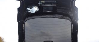
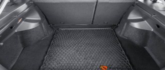
On another day off, I got ready and went to the garage to finish the trunk lighting that I had started a long time ago! A 60-centimeter white LED strip was taken as a light source and a wire was immediately purchased, and heat shrink instead of electrical tape:
In order not to make unnecessary connections, I unsoldered the “factory” wiring from the tape and immediately soldered it to the required (approximately) length:
And then the remaining work continues directly in the machine. I apologize for the quality of the photos, I only had my phone at hand, and the camera, to be honest, is not very good(
To make the tape stick better, I glued it to double-sided tape, cut it to the width of the tape, but not neatly, but it suits me:
I degreased the place where the tape will be attached so that it sticks better and dividing the tape in half (mentally) glue it in the middle so that the light is scattered evenly:
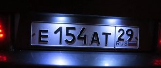
Well, it's a matter of connection. I did this, connected the minus to the trunk end switch so that when the trunk is opened, the backlight would turn on, but I connected the plus to the license plate illumination, of course it could also be connected to the headlight dimensions, well, these are extra wires at the headlight, otherwise you can’t see anything, it only lights up then, when the dimensions are on, I don’t need it during the day, but in the evening it’s fine and you can already indicate the car that it’s parked here, and the backlight will work.
We fix the lights and get acquainted with electrics
Since the main fault locations have been identified, you can safely move directly to methods for solving the problem. It is worth noting that with automotive electrics, not everything is so simple, but since this is a VAZ-2114, everything can be said very clearly here. Let's move on to methods for solving the problem.
Bulb
The first thing that needs to be checked is the lighting lamp, since its burnout can cause the light to go out in the car interior.
In order to get it out you will have to remove the lamp cover. After this, you need to check whether there is a filament, and insert the lamp into the control device or simply connect it to the battery. If the lamp lights up, then it is not the cause of the malfunction.
Ceiling lamp
More than once, the cause of the malfunction was the lamp itself, where the contact group simply melted and closed, which caused a burnout or a blown fuse.
To diagnose it, you will need to remove it from the car and visually inspect it. It is also recommended to ring the contacts going from the lamp to the wiring.
Fuse and relay for VAZ-2114
The next reason is a blown interior lighting fuse. This part can burn out due to a short circuit, which for various reasons occurs in the on-board circuit. Often the short circuit is caused by a malfunction of the lampshade.
The interior lighting relay is marked with an arrow. Often the contacts burn out and prevent the light from turning on.
Wiring
Electrical wiring is every car enthusiast's nightmare. For some, everything is clear, but for others, it’s a “dark forest.” So, during diagnostic operations, it is necessary to ring the wires going from the lampshade to the power supply or button.
Power fuses
The power fuse box is located under the hood and is located between the battery, strut support and coolant reservoir. Looks like a vertically mounted box. By removing the top cover, access to the power fuses appears.
F1 (50 A) - electric power steering . If the steering wheel turns hard, also check fuse F32.
F2 (30 A) - heater fan
F3 (60 A) - generator . If the battery discharges quickly or the discharge lamp is on, check this fuse, as well as the operation of the generator itself and its brush.
F4 (60 A) - generator
F5 (30 A) - low beam headlights . Also check relay K9 and fuses F12, F13.
When troubleshooting any electrical problems, use caution. Replace fuses and relays only with the engine off and the ignition off.
If your fleet contains not only Grants, you can also read about Kalina fuses and relays.
Relay block Lada Granta
The relays are located in the same fuse and relay box, which is located to the left of the steering column under the cover.
K1 - heater fan relay
K2 - power window relay . If they do not work, also check fuse F2; if this does not help, then the problem may be in the control unit.
K3 - starter relay . If it does not work (does not turn) and this relay is working, check the battery charge level. It could also be a problem with the retractor or the ignition switch and its contacts.
K4 - ignition switch terminal 15 relay
K5 - turn signal and hazard warning relay . If the turn signals come on and do not turn off, this relay may be shorted. Also check fuse F3 (emergency mode).
K6 - windshield wiper relay . Check also fuse F4.
K7 - high beam relay . Also check fuses F14 and F15 and the lamps themselves.
K8 - horn relay . Also check fuse F20, signal switch contacts on the steering wheel.
K9 - low beam relay . Also check fuses F12 and F13 and the lamps themselves.
K10 - rear window heating relay . If the heating does not work, the problem may be in fuse F8.
K11 - engine control unit relay . Also check fuse F1.
K12 - electric fuel pump relay . Also check fuse F21.
Door switches: where they are located, connection, checking
Initially, limit switches were installed on the doors to automatically turn on the interior lamp. Their connection scheme was the simplest - everything was connected in parallel, that is, it did not matter which door was open. In budget car configurations, only the driver's door switch was often installed.
Video: Problems with limit switches in Lada Vesta, Grant and Kalina
The weak link of such limit switches was the need to place them in an extremely inconvenient place: the protruding part of the metal sheet of the door in the lower corner pressed on them; less often, designers managed to place the limit switch higher. Because of this, they often failed even despite the sealing cap on the outside. For a car with an alarm, this meant randomly triggering the alarm at the wrong time, or, just as bad, being able to open the door without setting off the alarm.
Subsequently, the connection diagrams for limit switches in doors became more complex - initially to indicate a specific open door on primitive on-board computers. Here, each door had its own signal wire, which complicated the installation of alarms: since the limit switches need to be connected to the only input of the central unit, an attempt to connect it with all the limit switches immediately leads to a violation of the display on the on-board computer screen (shows all doors open at the same time). Because of this, it is necessary to use diode isolation, which allows you to logically combine the outputs of the limit switches without disturbing the operation of the computer.
It works simply: since the diode conducts current only in one direction, when any of the limit switches is closed, the alarm output is connected to ground in any case, but the pressed one is connected to the rest of the limit switch wires through a back-to-back pair of diodes that do not pass current.
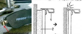
The solution to the problem with the reliability of limit switches turned out to be quite simple. It has long become the norm that the door end is located in the lock mechanism itself, that is, it is raised high and well protected from water, if, of course, the glass seal is in good working order. Note that the very principle of operation of the door limit switch has changed. If the door limit switch is installed in the slam, then it is triggered at a certain position of the door, closing the contacts when it begins to open.
If the door switch is in the lock, it is triggered by moving the locking mechanism: often (but not necessarily) it is enough to lift the handle without opening the door itself to close the contacts. This, by the way, makes installing alarms more convenient: you can leave the door open during operation by clicking the lock pawl with a screwdriver, and the alarm will no longer “see” the door open.
It is so good, for example, to adjust the shock sensor by arming the car with the door open, and not repeating the cycle “closed - armed - struck - disarmed - opened the door - changed the setting” for each adjustment.
On modern cars, the driver's door switch has received one more function - it is usually responsible for “falling asleep” and “waking up” of the on-board electronics. For this reason, on alarm systems with auto-start, it is necessary to connect a circuit simulating the opening of the driver’s door: the on-board controller at the end of the auto-start cycle will “see” that after turning off the ignition the door opened and closed, and will normally switch the car into a low-power mode.
In this case, a short-term “ground” pulse often appears on the limit switch wire, which, with a conventional diode isolation circuit, triggers an alarm for opening the door some time after arming. To avoid this, the diode decoupling circuit is complicated.
The difference with the previous diagram is that the diodes also cut into the standard wiring, and the alarm is connected between the diode and the limit switch. In this case, when the limit switch is closed, ground comes to both the standard vehicle on-board circuit control unit and the alarm system. But, when the controller creates a “ground” pulse in the standard wiring, the alarm input is blocked by back-to-back diodes, and no alarm is triggered.
It is important to understand that the duration of such pulses is very short, and the alarm can work correctly even when decoupled with one diode per line: for example, Sherkhans are less sensitive than StarLine, according to the author’s experience. But sometimes random operations are possible, and this is often associated with owner problems, when the limit switches are absolutely in good working order, but the car still sometimes “screams on its own.”
Backlight connection process
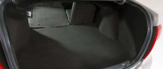
To connect the lighting in the trunk, you will need to stretch long wires from the dashboard under the floor covering through the entire car to the rear partition - there will be technological holes in it. In some cars you will have to remove the rear seat.
- The tape is carefully cut to the desired size at an equal distance from both LEDs. Be careful not to damage the diodes and the base of the tape; to do this, use a sharpened knife, or you can take a stationery knife. Then a red wire is soldered to the positive part of the tape, and a black wire to the negative part. Be sure to fill the joints with hot glue or silicone.
- Make the length of the positive red wire sufficient for comfortable accessibility of the fuse, that is, in a place convenient for the driver. It is necessary to carefully prime the hole in the body wall and insert a rubber bushing, through which the wire is then pulled.
- Cut the black negative wire at such a distance that it is long enough to lay under the front panel to the location of the button/toggle switch for turning on the backlight. Then we connect the second wire from the button to the body hardware.
- After soldering, carefully glue the strip with LEDs in the routing areas, also with the wires, which it is advisable to hide so that no one can see them.
Do-it-yourself trunk lighting will be clearer if you draw a diagram of the wiring, tapes and installation locations of the toggle switches on paper.
Fuse box
The fuse box in Grant is located to the left of the steering column, near the light switches. To remove the cover and access the fuses and relays, pull the top left side of the cover towards you. It’s made conveniently, everything is at hand and you don’t have to climb anywhere when getting up from the driver’s seat. Maybe this is a hint that they will often have to be changed, or maybe just convenience - the developers know better.
F1 (15 A) - engine control unit, injectors, ignition coil, cooling fan relay, short circuit 2x2.
If you have problems with electronics, and replacing this fuse does not help, in the worst case scenario, you will have to reflash the ECU or replace it. Also, if this fuse blows, the injectors and ignition coil stop working, which makes engine operation impossible. Therefore, if the Grant does not start, check this fuse first.
F2 (30 A) - electric windows.
If they do not work and replacing the fuse does not help, try unplugging it completely or removing the terminal from the battery for a couple of minutes, then connect it again. In this way, all temporary errors should be reset and if this is the case, the power windows will work again.
F3 (15 A) - alarm . If it doesn’t work, check this fuse, as well as the emergency light button, its contacts and the functionality of the lamps.
F4 (20 A) - windshield wiper, airbag . If the airbag warning light on the instrument panel comes on, check this fuse. The problem could be either in it, or in the electronic unit, or in the pillows themselves.
If the windshield wiper does not work and this fuse is intact, also check relay K6, the power handle, the reliability of the connectors connected to it, as well as the electric wiper drive itself.
F5 (7.5 A) - terminal 15 of the ignition switch. If you have problems turning on the ignition, check this fuse, as well as the reliability of the wire connections to the lock terminals.
F6 (7.5 A) - reverse lamp . If it does not work, but this fuse is intact, check the lamp itself, as well as the contacts connecting the connectors to the headlight.
F7 (7.5 A) - Mass air flow sensor, adsorber valve, oxygen sensor, speed sensor . If the engine runs erratically, does not idle, or stalls spontaneously, the problem may be this fuse or the corresponding sensor. We already had an article on how to check the mass air flow sensor.
F8 (30 A) - heated rear window . If it does not work, check this fuse, the terminals connecting the wires to the heater, and the integrity of its elements.
F9 (5 A) - right side lamps
F10 (5 A) - left side lamps . If the dimensions do not light up, the problem may be in these fuses or in the lamps themselves, as well as their connectors. It wouldn't hurt to check the headlight switch on the dashboard.
F11 (5 A) - rear fog lights . If they do not work, but this fuse is intact, the problem may be in the switch on the dashboard or in the lamps themselves, as well as their connectors
F12 (7.5 A) - right low beam lamp F13 (7.5 A) - left low beam lamp . If the low beam does not work in two headlights at the same time, the problem may be in the K9 relay, or in the low beam switch and its contacts. If only one lamp does not light, it is most likely the fuse or the lamp itself that needs to be replaced.
F14 (10 A) - right high beam lamp F15 (10 A) - left high beam lamp . If both high beam headlights do not work, the problem may be in relay K7. If there is only one, replace the fuse and/or lamp.
Lada Granta liftback (2019). Guide - part 3
If during a call (while the 3 key is illuminated
SOS" flashes red) initiated
by pressing the 3 " key
SOS", press key 3 again
SOS" and hold for at least 2 seconds, then emergency
the call will be canceled (key 3" backlit
color will be turned off).
The SVEOS is in this mode if no emergency call is made and if the ignition is turned off. In the “Off” mode, there is no backlighting of key 3 “
SOS”, and also the indicator 4 of the system status is not lit.
. In the “Off” mode, SVEOS does not respond to
pressing key 3 "
SOS". SVEOS exit from mode
“Off” is performed when the ignition is turned on.
The testing mode is intended to check the functionality of the SVEOS components. In the testing mode, the functionality of the SVEOS status indicator, the microphone and loudspeaker in the interior lighting unit, the backup battery and other internal components of the SVEOS is checked. If you wish, you can independently check the performance of the SVEOS by running the test mode. To start the test mode, you must: – make sure that the engine is turned off; – turn the key in the ignition switch (ЗЗ) to the “Ignition on” position and wait 1 minute; – turning the ignition off and on three times. After the 3rd switching on of the ignition (switching ZZ No. 6), the SVEOS goes into test mode if the engine did not start during the entry procedure.
In this case, the sound prompt “Testing procedure has started” will be played. During testing, the functionality of the microphone and loudspeaker will be checked. After playing the sound prompt “Say the control phrase”, you will need to say any phrase lasting no more than 5 seconds. Immediately after this, the audio prompt “Playing a control phrase” will be played and then the phrase you spoke will be played. The audio prompt “Enter your verification result” will then play. If testing of the microphone and loudspeaker was successful, then it is necessary to switch the protection zone 2 times according to the algorithm described below within no more than 3 seconds:
When do you need to adjust headlights on a Grant?
The main motive for working with headlights is insufficient road lighting. There are many reasons for this:
- From the factory the car comes with a low beam adjusted for the driver's weight of 75 kg . This is a universal setting - if your weight is different, you need to adjust it immediately after purchase;
- the hydraulic corrector has failed - when it breaks, the headlights either shine crookedly or are not adjusted at all;
- Driving over bumps and potholes over time leads to changes in the settings of the light beam;
- buying a car second-hand - it is not known exactly how the lights were set up by the previous owner.
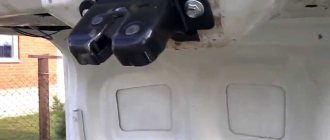
Trunk limit switch
Standardly, a limit switch is installed in the trunk to activate the backlight in it; on cars with a standard alarm system, it also serves to control opening during active security. The limit switch can also be used by the standard central locking, blocking locking if the trunk is not slammed shut.
If we are talking about a cheap car with a minimum configuration, then you will have to connect the trunk limit switch yourself when installing the alarm. It’s easiest for owners of those cars where more expensive equipment includes a standard trunk alarm switch: as with doors, here it is enough to install the original part in the designated place. Otherwise, alas, you will have to drill a hole and install a universal one. Increasingly, the switch is not installed as a separate part in the trunk, but is built into the lock itself, as is the case with the doors.
Sometimes this leads to serious problems: for example, on the Renault Koleos, a failure of the trunk locking mechanism has become a “trademark disease”, and in the author’s practice, the “anti-record” is only a week after purchasing a new car. The lock, not locking, did not allow the built-in limit switch to operate, and this, as on other cars on similar platforms, blocked the locking of the central locking as a whole; due to the non-locking trunk, the owner could not lock the doors. In such cases, it was necessary to tightly block the trunk lock in a locked state until a new one arrived for a warranty replacement.